Mar 12, 2010 - of controlling the q and the d component of the rotor's currents ... Fault Ride Through (FRT) or Low Voltage Ride Through ... stator flux, as well as to get rid of several transformations. Finally ... power to the grid from the electrical machine point of view .... second order generalized integrator (SOGI) [13]-[14].
Control Strategies for DFIG Wind Turbines Under Grid Fault Conditions Luna, A.* Rolan, A.* *Technical University of Catalonia Department of Electrical Engineering Barcelona – SPAIN
Medeiros, G ♠ Rodríguez, P.* ♠ Federal University of Pernambuco Department of Electrical Engineering Recife – BRAZIL
Abstract — The classical control techniques for regulating the active and reactive power delivery in doubly fed induction generators (DFIG), for wind power applications, are normally based on voltage oriented control (VOC) strategies. Among these algorithms, those that work in a synchronous reference frame, attached to the magnetic flux vector, became very popular. In spite of the good behaviour of such algorithms their performance depends highly on an accurate detection of the stator flux position, something that can be critical under unbalanced or distorted grid voltage conditions. This paper presents a new VOC strategy able to control the operation of a DFIG in the αβ reference frame, with no need of flux position estimation, something that conducts to a more simple and robust algorithm. In order to evaluate the advantages of this new control proposal, namely VOC-RRF, their performance will be compared with the response obtained with a classical VOC algorithm by means of PSCAD/EMTDC® simulation models. I.
Teodorescu, R.● Aalborg University Institute of Energy Technology Aalborg – DENMARK ●
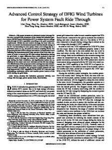
implemented [5], in order to control the injection of active/reactive power oscillations that appear when the grid voltage is unbalanced. Nowadays, all the existing grid codes include fault ridethrough requirements for wind turbines [6]. These standards determine the fault boundaries among the ones a grid connected wind turbine shall remain connected to the network, giving rise to specific voltage profiles that specify the depth and clearance time of the voltage sags that wind turbines must withstand without tripping. Such requirements are known as Fault Ride Through (FRT) or Low Voltage Ride Through (LVRT) and they are described by a voltage vs. time characteristic, denoting the minimum required immunity of the wind power station. In addition to this requirement several Transmission System Operators (TSO) provide also a profile with the injection of active/reactive power that shall be injected during the fault, in order to support the grid voltage. This is the case of the German (e-on) [7] and Spanish (REE) [8] grid codes depicted in Fig.1
INTRODUCTION
A
T the present time the 50% of the installed wind turbines (WT) worldwide are based on DFIGs, which are connected to the electrical network through back to back converters [1]-[2]. The classical power control systems for DFIG-WTs are normally based on voltage oriented control (VOC) algorithms [3]. The most extended version of such systems takes advantage of the field oriented control (FOC) principle. Regarding this method, an accurate synchronization with the stator flux vector enables to perform a decoupled control of the injection of active (P) and reactive (Q) powers, by means of controlling the q and the d component of the rotor’s currents in the Park’s synchronous reference frame. From now on this VOC algorithm will be referenced as voltage oriented control in the synchronous reference frame (VOC-SRF) [4]. The synchronous reference frame transforms enables the VOC-SRF to treat the state variables of the generator as continuous signals, so the tuning of the controller can be easily done. However, the high dependence of the stator flux position estimation in this kind of controllers is a serious drawback. This is especially critical when the system is affected by unbalanced grid voltage fault conditions, as in this situation the flux estimation is not straightforward due to the appearance of negative and positive sequence flux vectors that must be decoupled. In addition an independent control in the positive and negative sequence for the rotor side converter should be
978-1-4244-4649-0/09/$25.00 ©2009 IEEE
(a)
(b) Fig. 1. Injection of reactive power demanded by e-on (a) and REE (b)
3886
Authorized licensed use limited to: UNIVERSITAT POLITÈCNICA DE CATALUNYA. Downloaded on March 12,2010 at 03:45:31 EST from IEEE Xplore. Restrictions apply.
This control action should start as soon as possible when the sag appears, hence a fast dynamical response of the current controller of the rotor side converter is necessary. The aim of this paper is to present a new control system for DFIG-WTs, called voltage oriented control in the rotor reference frame (VOC-RRF), able to improve the response of classical controller under unbalanced conditions. As the classical the VOC-RRF algorithm it will be also based on a VOC algorithm, but as a difference with the previous ones it will be not a FOC system, something that would permit to isolate its behaviour from the errors in the detection of the stator flux, as well as to get rid of several transformations. Finally, in order to analyze the performance of this control its response will be tested and compared with a classical VOCSRF algorithm.
In this equation the measured stator voltage r d is represented rd by v abc , and the resulting stator currents are i abc . The unitary vector in this case is following the shape of the stator voltage, as a consequence, any current injected in this direction will produce only active power. In the same manner the injection of reactive power could be achieved by injecting currents in-quadrature with the stator rq voltage. In (4) vabc is a three-phase signal with the same amplitude and frequency of rd r q the stator voltage, but shifted 90º. The addition of i abc and i abc will be finally the stator current that would provide the desired P* and Q* simultaneously as given by (5).
II. POWER CONTROL BASED ON VOC-RRF The classical VOC theories tend to control the injection of power to the grid from the electrical machine point of view [9]. As the equations of the DFIG show [5], the electromagnetic torque of the generator is linked to the ‘q’ component of the rotor current. Any variation in this torque produces a change in the active power that is being injected to the grid. Therefore, a closed loop control of this rotor variable permits to adjust the active power delivery at the stator windings [10]. An analogous reasoning for the reactive power can be done using the ‘d’ component of the rotor’s current. However the control of a DFIG-WT can be performed considering a different sense of the power flow, from the electrical grid to the electrical generator. Following this reasoning it is possible to determine the stator current that should be injected in order to produce a certain value of P and Q. Later the rotor currents which are necessary in order to achieve the desired stator currents can be calculated and injected to the rotor windings. A. VOC-RRF Algorithm This algorithm, that was first presented in [11], focus the problem of controlling the P and Q delivery from another point of view. The instantaneous active and reactive powers related to generic voltage and current vectors, v and i, in a three-phase system can be written as: p = v ×i
(1)
q = v ´ iq = v^ × iq
(2)
Where v ^ are a set of in-quadrature signals with respect the measured grid voltage, v [12]. Regarding (1) and (2) the currents that are needed to achieve a certain value of P at the stator windings can be calculated as follows (3). rd P* r d éëi abc ùû = r 2 × v abc d v abc
978-1-4244-4649-0/09/$25.00 ©2009 IEEE
(3)
rq Q* r q éëi abc ùû = r 2 × v abc q v abc
(4)
r rd rq i abc = i abc + i abc
(5)
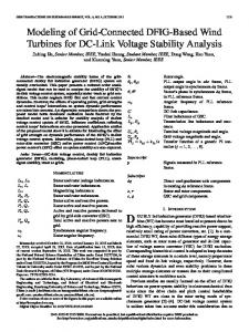
In a DFIG the direct and quadrature current components at the stator windings can be controlled through the rotor. Therefore it is possible to determine the shape of the currents to be injected at the rotor side in order to obtain the desired output power at the stator. The layout of the proposed control topology for the rotor side converter of the DFIG is shown graphically in Fig. 2. As it is depicted in the figure the stator voltage, as well as the active and reactive power set points, constitute the main references in this control structure. Those signals are processed by the different blocks of the VOC-RRF algorithm, determining finally a rotor current set point for the rotor side converter. In this algorithm the αβ transformation permits to work with an orthogonal system, something useful in order to cancel out the influence of the homopolar sequence components. In this strategy it is necessary to control the currents that are in phase with the stator voltage, as well as those in-quadrature with this reference. The in-quadrature system can be found easily considering the direct αβ sequence and operating as it is shown in (6). é0 -1ù rq rd éëvab ùû = [ H ] éë vab ùû ; [ H ] = ê (6) ú ë1 0 û The unitary vector in both directions can be easily found once the αβ components of the stator voltage are known. The direct reference frame has the same unitary vector of this voltage (7). æ ö 1 rd ÷ [ I ] é vrab ù éëvab ùû = ç (7) 2 2 ç v +v ÷ ë û b ø è a As the control action is performed by means of the rotor currents, it is necessary to represent the stator voltage in the rotor reference frame, so it is necessary to represent these variables in a rotational reference frame. This can be done
3887
Authorized licensed use limited to: UNIVERSITAT POLITÈCNICA DE CATALUNYA. Downloaded on March 12,2010 at 03:45:31 EST from IEEE Xplore. Restrictions apply.
Fig 2.- VOC-RRF control of the rotor-side power converter in the αβ reference frame.
thanks to G , as shown in (8), where q r is the electrical angle of the rotor, that is equal to the mechanical angle multiplied by the pair of poles of the generator. é cos q
[ G ] = ê - sin qr ë
sin q r ù cos q r úû
r
(8)
In this point it is worth to mention that this step could be merged with the ab transformation, M, yielding finally (9). r dq r ëévab rs ùû = [ G ][ M ][ vabc ]
(9)
In that way it will be possible to determine the shape of the rotor currents to be injected in order to produce the desired output power at the stator windings as shown in (10). uuur éi * ù = P ë ab r û r d vab rs
2
Q rd éë vab ù+ rs û rd vab rs
rq éë vab ù rs û
2
(10)
rd
Where vab rs is the magnitude of the vector (11), and rd rq éëvab ù and éëvab ù are the measured direct and in-quadrature rs û rs û voltages of the stator in the rotor reference frame. rd = vab rs
(v ) + (v ) d a rs
2
d b rs
2
(11)
The value of the rotor currents to be injected is then the result of the addition between the ‘active’ and ‘reactive’ components, as it stands out clearly in (12). éia*r ù P ê* ú= r d i ëê b r ûú vab rs
2
é vad ù Q × ê drs ú + r d v ëê brs ûú vab rs
2
Once the current set point is calculated it is necessary to implement a proportional resonant (PR) controller [18], as the input signals are sinusoidal waveforms whose frequency is equal to the slip of the generator.
évaq ù × ê qrs ú ëêvb rs ûú
978-1-4244-4649-0/09/$25.00 ©2009 IEEE
(12)
PR = k p +
ki ( ws - wr ) s s 2 + ( ws - wr )
2
(13)
However, and due to the fact that this value changes depending on the speed of the rotor, the resonant frequency should be adaptive in (13). The second term of (27) is a second order generalized integrator (SOGI) [13]-[14]. This kind of transfer function has been broadly used in gridsynchronization applications [21], and permits to cancel out the error in the current injection at the specified frequency. The current controller can be extended to the negative sequence components just by adding another resonant controller tuned at ws + wr , that would permit to inject negative sequence currents. The implementation of this dual controller in the VOC-RRF is simpler than in the classical VOC-SRF where a new rotating reference frame must be set. III. POSITIVE AND NEGATIVE SEQUENCE CURRENT INJECTION The resulting current setpoint written in (12) have been calculated without considering that the output current at the stator windings may have undesirable symmetrical components. In equation (5) the desired output currents are obtained, however previous strategies can be applied in order to control whether this currents will have negative sequence or not. In some cases it could be necessary to inject only sinusoidal currents, while in other situations the cancellation of active power oscillations may be the main objective. In the following different strategies for determining the shape of the injected currents, that were first published in [12] for grid connected power converters, will be briefly presented.
3888
Authorized licensed use limited to: UNIVERSITAT POLITÈCNICA DE CATALUNYA. Downloaded on March 12,2010 at 03:45:31 EST from IEEE Xplore. Restrictions apply.
A. Instantaneous Active and Reactive Control (IARC) From (1)-(2) the active and reactive current references to deliver the powers P and Q to the grid are given by: P
i*p = i*q =
2
v Q v
2
v ,
Therefore the amplitude of the oscillations in p and q will depend on the values of P and Q. Then, a delivery of full active power will produce a constant value of p while the q component will have an oscillatory term. This relationship is swapped if just Q is delivered to the grid. C. Balanced Positive Sequence (BPS)
(14)
v^ .
(15)
In this case the shape of the i*p and i*q currents are obtained thanks to the instantaneous voltage signal, v and its quadrature component, v ^ . From now on it will be assumed that the power references P and Q are constant throughout a grid period.
When the quality of the currents injected in the grid plays a decisive role, the voltage vector in (14) and (15) can be substituted by its positive-sequence component and the current references are given by (24) and (25). Assuming that the current injected by the inverter perfectly track the current references, the instantaneous active and reactive power delivered to the grid, p and q, differ from the power references, P and Q, because of the interaction between the injected current, i* = i*p + i*q , and the negative-sequence grid voltage (26)-(27).
B. Positive-Negative Sequence Compensation (PNSC)
i*p =
Assuming that currents injected to the grid can be unbalanced but not distorted during grid faults, that is i = i + + i - , the instantaneous powers delivered to the grid are given by: p = v × i = v+ × i+ + v- × i- + v+ × i- + v- × i+ + ^
+
^
-
+ ^
-
^
q = v^ × i = v × i + v × i + v × i + v × i
i*q =
(16) +
(17)
The active and reactive current references can be calculated by imposing the following constrains on (16) and (17) v + × i*p+ + v - × i*p- = P , v + × i*p- + v - × i*p+ = 0 ,
(18)
v +^ × i*q+ + v -^ × i*q- = Q , v +^ × i*q- + v -^ × i*q+ = 0 .
(19)
P v
+ 2
Q v+
2
v+ ,
(24)
v +^ .
(25)
p = v × i* = v + × i*p + v - × ( i*p + i*q ) , { 14243 P p%
(26)
q = v ^ × i* = v +^ × i*q + v -^ × ( i*p + i*q ) . { 14243 Q q%
(27)
In this case an unbalanced voltage guarantees the appearance of p% and q% for any not-null value of P and Q. IV. GRID VOLTAGE FREQUENCY DETECTION
Operating from (18)-(19) as it is shown in [15], the active and reactive reference currents are given by: i*p =
i*q =
P v
+ 2
-v
- 2
(v
- 2
(v
Q v
+ 2
-v
+
+ ^
- v- ) ,
(20)
- v -^ )
(21)
If the currents shown in (20) and (21) were injected in the unbalanced grid, the instantaneous powers would differ from the power references because of the interaction between voltage and current vectors with different sequence and direction, that is: p = v × ( i*p + i*q ) = v + × i*p+ + v - × i*p- + v + × i*q- + v - × i*q+ , 1442443 1442443 P p%
V. SIMULATION PLATFORM AND RESULTS (22)
q = v ^ × ( i*p + i*q ) = v +^ × i*q+ + v -^ × i*q- + v +^ × i*p- + v -^ × i*p+ . 1442443 1442443 (23) Q q% 978-1-4244-4649-0/09/$25.00 ©2009 IEEE
In this work a frequency locked looked loop system, namely Dual Second Order Generalized Intregrator – Frequency Locked Loop (DSOGI-FLL), has been used for detecting the fundamental frequency of the grid voltage, w , that is necessary for tuning the resonant controllers of the VOC-RRF. This synchronization system was first presented in [21], where it was proven its accurate and fast estimation of the voltage variables under unbalanced and transient conditions of the electrical network. The layout of the DSOGI-FLL is shown in Fig.3. This synchronization algorithm permits estimating the positive- and negative-sequence components of the grid voltage using the instantaneous symmetrical components (ISC) method on the a-b stationary reference frame [14].
The performances of the VOC-SRF and VOC-RRF control systems presented in this paper have been tested in simulation using PSCAD/EMTDC. As a matter of the paper length just the results for the IARC current control strategy for the VOCRRF case have been displayed.
3889
Authorized licensed use limited to: UNIVERSITAT POLITÈCNICA DE CATALUNYA. Downloaded on March 12,2010 at 03:45:31 EST from IEEE Xplore. Restrictions apply.
w¢
w ff
e
w¢
ò
g
vab
va
1 2
v
w’ 1 2
v
-1
qv¢
va+¢ vb+¢
va¢ qva¢
e v’ qv’
SOGI-QSG( )
vb
In Fig 5 the behaviour of the VOC-SRF under such conditions is shown. In Fig.5.b the grid voltage waveforms show how in t = 3s a negative sequence component appeared in the three phase signal. In Fig.5.a it can be realized how the active power delivered through the stator begins to oscillate. The currents in the stator are shown in Fig.5.c and Fig.5.d, being the second one a zoom performed around 3 – 3.05 sec. The behavior of the rotor currents have been displayed in Fig.5.e. In this plot it can be noticed how the rotor converter is trying to inject some negative sequence voltage. However as a classical controller has been implemented the system is unable to control this sequence, giving rise to power oscillations in the stator.
FLL
DSOGI w’
ef
+ ¢ vab
v¢b
e v’ qv’
qvb¢
va-¢ vb-¢
SOGI-QSG( )
- ¢ vab
PNSC
v w¢
ev
ò
k
SOGI
ò
v¢
qv¢ e
Fig 3.- Block diagram of the DSOGI-FLL.
The layout of the model is depicted in Fig.6, where the DFIG parameters that are implemented in the simulation are shown in Table I.
(a)
(b)
(c)
(d)
TABLE I SPECIFICATIONS OF THE SIMULATED SYSTEMS. Machine parameters Apparent power Rated stator voltage Rated angular frequency Mutual inductance Stator leakage inductance Rotor leakage inductance Stator resistance Rotor resistance
Values 100 kVA 220 V 376.99 rad/s 4.362 pu 0.102 pu 0.110 pu 0.0054 pu 0.0060 pu
In this model the power converters are controlled as current sources, using commutated models of IGBT converters that are driven by means of PWM signals, whose carrier frequency is equal to 10 kHz.
Fig 4.- Simulation model programmed in PSCAD
Significant differences between both controllers can be found when the grid voltage becomes unbalanced. These conditions where reproduced in a second simulation test, where the grid voltage became unbalanced after t = 3s.
978-1-4244-4649-0/09/$25.00 ©2009 IEEE
(e) (f) Fig 5.- Performance of the VOC-SRF control strategy when the grid voltage is unbalanced (a) Active power delivery; (b) Grid voltage waveforms; (c) Currents at the stator windings; (d) Zoom of the stator currents between 3.05 and 3.1 sec.; (e) Currents injected by the rotor side converter; (f) Voltage at the rotor windings ( filtered ).
In addition the voltage unbalance affects negatively the estimation of the flux position that is necessary for the VOCSRF control. Finally a filtered signal of the rotor voltage is depicted in Fig.5.f. The same test was done using the proposed VOC-RRF. In this case, due to the fact that a current control for the negative sequence can be easily implemented just by adding a resonant controller, the results regarding the active power delivery were better. In Fig.6.a the active power delivered through the stator show a little ripple,that can be almost neglected when the unbalance voltage appear.
3890
Authorized licensed use limited to: UNIVERSITAT POLITÈCNICA DE CATALUNYA. Downloaded on March 12,2010 at 03:45:31 EST from IEEE Xplore. Restrictions apply.
(a)
(b)
(c)
(d)
in function of the desired active and reactive power delivery, something that enhances the bandwidth of the controller. Additionally this controller permits controlling the negative sequence of the current that is being injected to the grid. The simulation and experimental results have demonstrated that the VOC-RRF can be considered as a good alternative for the classical VOC-SRF control algorithm as its performance has been proven to be robust and fast. This can be of particular interest when controlling DFIG-WTs under fault conditions, as the VOC-RRF control has no need of estimating the phase of the stator flux, something critical in classical control systems. This feature makes this control topology specially robust under such conditions, what it turns opens a broad field of improvement in the design of control systems able to enhance the fault ride through (FRT) of DFIG-WTs. REFERENCES [1] [2]
[3]
[4] (e) (f) Fig 6.- Performance of the VOC-RRF control strategy when the grid voltage is unbalanced (a) Active power delivery; (b) Grid voltage waveforms; (c) Currents at the stator windings; (d) Zoom of the stator currents between 3.05 and 3.1 sec.; (e) Currents injected by the rotor side converter; (f) Voltage at the rotor windings ( filtered ).
The stator currents that where calculated thanks to (3) give rise to current waveforms that produce a constant active power delivery. These currents are shown in Fig.6.c and Fig.6.d. The shape of this stator currents are controlled through the rotor converter, that injects the appropriate currents in the rotor to synthesize the desired stator currents according to equation (12). As in the previous case the rotor side voltage is shown in Fig.6.e, in order to show that the voltage in these windings remain between controllable limits. In this point it is important to highlight that none of the tested algorithms have produced overcurrents or overvoltages, yielding a stable operating conditions when transients in the active power or in the grid voltage occur. In addition, the simulation results have proven that both control algorithms are able to offer satisfactory results under grid voltage balanced conditions. However remarkable differences can be found when the voltage is unbalanced.
[5] [6] [7] [8] [9]
[10]
[11]
[12]
[13]
VI. CONCLUSIONS The present paper has introduced a new proposal for improving the operation of DFIG-WTs under unbalanced conditions. This new power control philosophy for that topology has been called VOC-RRF. This algorithm permits an easier control of the system, as its structure gains in simplicity if compared with the classical VOC-SRF system. However its main contribution lies in its feed forward behaviour, that permit to determine directly the rotor currents 978-1-4244-4649-0/09/$25.00 ©2009 IEEE
[14]
[15]
Blaabjerg, F. ; Chen, Z., “Power Electronics for Modern Wind Turbines” Synthesus Lectures on Power Electronics, 2006 Akhmatov, V.; “Analysis of dinamical behavior of electric power systems with large amount of wind power”. PhD dissertation Orsted-DTU, 2003. R. W. De Doncker and D. W. Novotny, “The universal field oriented controller”. IEEE Transactions on Industry Applications, vol. 30, No 1, p. 92-100, 1994. W. Leonhard, Control of electrical drives, 3rd ed. New York: Springer, 2001. 470 p. Krause, P.; Wasynczuk, O. & S., S. “Analysis of Electric Machinery and Drive Systems” – second edition. Wiley-IEEE Press, 2002 F. Iov, A. Hansen, P. Sorensen, and N. Cutululis, “Mapping of grid faults and grid codes” Risoe, Tech. Rep., 2007. e-on, “Grid code - high and extra high voltage,” www.eon-netz.com, April 2006. REE, “Po-12.3 requisitos de respuesta frente a huecos de tension de las instalaciones eolicas,” BOE num. 254, October 2006. Pena, R.; Clare, J. & Asher, G. “A doubly fed induction generator using back-to-back PWM converters supplying an isolated load from a variable speed wind turbine”. Electric Power Applications, IEE Proceedings-, 1996, 143, 380-387 R. Pena, J. C. Clare and G. M. Asher, “Doubly fed induction generator using back-to-back PWM converters and its application to variable-speed wind-energy generation”. IEE Proceedings - Electric Power Applications, vol. 143, No 3, p. 231-241, 1996. A. Luna, K. Lima, P. Rodríguez, E. Watanabe, R. Teodorescu., “Comparison of power control strategies for DFIG wind turbines”. Industrial Electronics, 2008. IECON 2008. 34th Annual Conference of IEEE Rodriguez, P.; Luna, A.; Teodorescu, R.; Iov, F. & Blaabjerg, F. ”Fault ride-through capability implementation in wind turbine converters using a decoupled double synchronous reference frame PLL”. Power Electronics and Applications, 2007 European Conference on, 2007 Yuan, X., Merk, W., Stemmler, H., and Allmeling, J., “Stationary frame generalized integrators for current control of active power filters with zero steady-state error for current harmonics of concern under unbalanced and distorted operating conditions,” IEEE Trans. Ind. Appl., vol. 38, no.2, pp. 523–532, Mar./Apr. 2002. Rodriguez, P.; Luna, A.; Ciobotaru, M.; Teodorescu, R. & Blaabjerg, F. “Advanced Grid Synchronization System for Power Converters under Unbalanced and Distorted Operating Conditions” Industrial Electronics, 2006 IEEE 32th Conference on, 2006. P. Rodriguez, A. V. Timbus, R. Teodorescu, M. Liserre, and F. Blaagjerg, “Independent pq control for distributed power generation systems under grid faults,” in IEEE Industrial Electronics, IECON 2006 , Nov. 2006, pp. 5185–5190.
3891
Authorized licensed use limited to: UNIVERSITAT POLITÈCNICA DE CATALUNYA. Downloaded on March 12,2010 at 03:45:31 EST from IEEE Xplore. Restrictions apply.