International Journal of Power Electronics and Drive System (IJPEDS) Vol. 7, No. 4, December 2016, pp. 1337~1347 ISSN: 2088-8694, DOI: 10.11591/ijpeds.v7i4.pp1337-1347
1337
Vector Control Realization of DFIG Under Grid Abnormalities using Real Time Digital Simulator Kanungo Barada Mohanty1, Satish Choudhury2, Madhu Singh3 1
Department of Electrical Engineering, National Institute of Technology Rourkela, India 2 Department of Electrical Engineering, ITER, SOA University, Bhubaneswar, India 3 Department of Electrical Engineering, National Institute of Technology Jamshedpur, India
Article Info
ABSTRACT
Article history:
A grid connected doubly-fed induction generator (DFIG) system, driven by variable speed wind turbine is considered in this research to satisfy grid code requirements. Remaining grid synchronized and stable under voltage sag and voltage swell, obtaining power control through dc link voltage control, and providing unity power factor at grid terminals are the achievements. The DFIG system uses two back-to-back converters. Vector control strategy is used with the grid side and rotor side converters, and taken up for research for further improvement. The grid side converter controls dc-link voltage and maintains unity power factor at the grid connection point. The rotor side converter supplies the reactive power of the machine and maintains the speed constant irrespective of the transient behavior of the grid. In this paper the behavior of the DFIG system is analyzed under grid voltage fluctuation and the experimental results are obtained using RT-LAB. Main contribution of this work is in improving the DFIG system performance with grid low voltage and over voltage ride through capability through simulation, and its real time experimental verification.
Received Apr 18, 2016 Revised Nov 22, 2016 Accepted Dec 5, 2016 Keyword: Doubly-fed induction generator Grid abnormalities Grid-side converter Real time digital simulator Rotor side converter Vector control
Copyright © 2016 Institute of Advanced Engineering and Science. All rights reserved.
Corresponding Author: Kanungo Barada Mohanty, Department of Electrical Engineering, National Institute of Technology Rourkela, Rourkela-769008, India. Email:
[email protected]
1.
INTRODUCTION Performance improvement of doubly fed induction generator (DFIG) under grid voltage fluctuation is the focus of many researchers. The control strategy must satisfy grid codes such as grid stability, fault ride through (FRT), power quality improvement, grid synchronization and power control etc. DFIG system uses back-to-back converters in the rotor circuits to meet the necessary requirements. The power converter need only be rated to handle the rotor power [1]. Independent control of active and reactive power from the grid or to the grid is possible by vector control of line side converter [2]. Different control techniques are used to improve FRT capability of DFIG system. Such system using a robust linear quadratic (LQ) controller is realized in [3] to improve the FRT capability as well as the generator performance under grid voltage unbalance. A series converter on the stator terminal is used to mitigate the effect of the short circuit on the wind turbine [4]. A controller is proposed which uses the positive and negative sequence component to work under FRT [5]. It has been shown that both even harmonics and odd harmonics appear in dc link voltage and ac side input currents respectively during unbalanced 3-phase grid voltages [6]. Induction generator dynamics during grid faults is studied in [7]. Performance improvement of DFIG during grid voltage unbalance is achieved in [8] through direct power control. A novel control strategy of induction generator during voltage dip is presented in [9]. Performance improvement of DFIG-based wind farms during grid unbalance is studied in [10]. During grid voltage sag, reactive power control of DFIG is discussed in [11]. A study of dynamics of DFIG-based wind turbines during grid voltage dip is done in [12]. Effects of the transmission Journal homepage: http://iaesjournal.com/online/index.php/IJPEDS
IJPEDS
ISSN: 2088-8694
1338
line faults for a grid connected wind farm with different types of generators are discussed in [13]. LVRT capability improvement and stability improvement of a DFIG based wind power system are presented in [14]. In this paper, voltage control technique is used in both grid-side as well as machine-side converters to analyze the performance of the DFIG system under grid voltage fluctuation and the experimental results are obtained using Real Time Digital Simulator [15] where RT-LAB is used. In RT-LAB hardware synchronization mode is selected to synchronize the software environment with the hardware environment via an analog peripheral OP5251.
2.
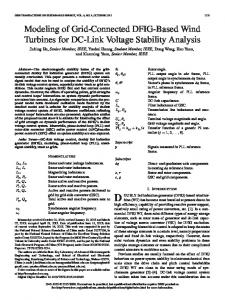
MODELING OF DFIG The schematic diagram of the overall system is shown in Figure 1. A 10 hp wound rotor induction machine is modeled in synchronous reference frame. Two voltage fed PWM converters are used. One converter is used in the grid side and other is in the rotor side. The objective of grid side converter is to maintain dc-link voltage constant and the rotor side converter regulates the speed, thus making the system suitable for variable speed application system. Equations (1)-(4) and (8)-(9) describe the complete machine model in state-space form where Ψqs, Ψds, Ψqr, Ψdr are the state variables. d qs R b vqs e ds s qs qm dt b Xls
(1)
d ds R b vds e qs s ds dm dt b Xls
(2)
d qr r Rr b vqr e qr qm dr X dt b lr
(3)
d dr r Rr b vdr e qr X dr dm dt b lr
(4)
Where
qm
X ml X qs ml qr X ls X lr
(5)
dm
X ml X ml X ls ds X lr dr
(6)
X ml
X m X ls X lr X ls X lr X m X lr X m X ls
(7)
The development of torque by the interaction of air gap flux and rotor mmf is expressed in eqn. (8) in terms of d-q- components of stator flux and current.
3 p 1 Te i qsids 2 2 b ds qs
(8)
The speed ωr in the above equations cannot be treated as constant. It can be related to the torque as
Te Tm J
dm 2 d Tm J r dt p dt
(9)
The system setup is described in the next section. Vector Control Realization of DFIG Under Grid Abnormalities using Real Time Digital … (K.B. Mohanty)
1339
ISSN: 2088-8694
Figure 1. Schematic diagram of wind turbine driven DFIG system with proposed grid side and rotor side converter vector control
3.
REAL TIME SETUP This simulator is developed with the aim of meeting the transient simulation needs of electromechanical drives and electric systems while solving the limitations of traditional real-time simulators. It is based on a central principle: the use of widely available, user-friendly, highly competitive commercial products (PC platform, Simulink™). The real-time simulator consists of two main tools: a real-time distributed simulation package (RT-LAB) for the execution of Simulink block diagrams on a PC-cluster, and algorithmic toolboxes designed for the fixed-time-step simulation of stiff electric circuits and their controllers. Real-time simulation and Hardware-In-the-Loop (HIL) applications are increasingly recognized as essential tools for engineering design, especially in power electronics and electrical systems [15]. The present real-time simulator is based on RTLAB real-time, distributed simulation platform. It is optimized to run Simulink in real-time, with efficient fixed-step solvers, on PC Cluster. Based on COTS non-proprietary PC components, RTLAB is a modular real-time simulation platform, for the automatic implementation of system-level, block diagram models, on standard PC‟s. It uses the popular MATLAB/Simulink as a front-end for editing and viewing graphic models in block-diagram format. The block diagram models become the source from which code can be automatically generated, manipulated and downloaded onto target processors (Pentium and Pentium-compatible) for real-time or distributed simulation. Electric and power electronic systems are created on the host personal computer by interconnecting: a. Electrical components from component model libraries available in the Power System Block-set b. Controller components and other components from Simulink and its toolboxes that are supported by Real-Time-Workshop c. I/O blocks from the simulator I/O toolboxes. The easy-to-use drag-and-drop Simulink interface is used at all stages of the process. These systems are then simulated and tuned off-line in the MATLAB/Simulink environment. ARTEMIS fixed step solvers are used for the electric part and Simulink native solvers for the controller and other block-diagram parts. Finally, the model is automatically compiled and loaded to the PC-Cluster with RT-LAB simulation interface. The simulator software converts Simulink and Sim Power Systems non-real-time models to real-time simulation.
4.
GRID SIDE CONVERTER CONTROL Grid voltage may change due to sudden load change or wind speed variation in weak grid and in micro-grid. If the grid voltage changes, the voltage of DFIG stator and rotor also change. This affects the IJPEDS Vol. 7, No. 4, December 2016 : 1337 – 1347
IJPEDS
ISSN: 2088-8694
1340
DFIG performance. Since the converters are connected back-to-back, the same effect is also observed across these two converters and on the dc-link capacitor as well. Under normal operating conditions, peak value of grid phase voltage (vabcmax) is taken as 380V and dc link voltage as 850 V. The maximum value of amplitude modulation index of grid side converter (ma1) is set at 0.89, for linear modulation. The following relation between peak grid phase voltage, dc link voltage and modulation index holds good [16]. vabcmax= ma1 vdc/2 The necessary control action is adopted to maintain the dc-link voltage constant. Grid voltage oriented vector control technique is used, in which the real axis of the grid voltage vector is chosen as the d-axis. Phase Locked Loop block is used to measure the system frequency and provides the phase angle θ for the d-q transformations block. The control scheme utilizes current control loops for i d and iq with the id demand being derived from the dc-link voltage error through a standard P-I controller. The iq demand determines the displacement factor on the grid side of the choke. The active power and reactive power is controlled independently using d-q component of the current governed by (10) and (11).
3 P (vd id vqiq ) 2
(10)
3 Q (vd iq vqid ) 2
(11)
The reference voltage vectors for the grid side converters are found from (12) and (13).
vd* vd iq*e L id* R v'd
(12)
vq* vq id*e L iq*R v'q
(13)
Where, v‟d and v‟q are found from the current errors through standard P-I controllers.
5.
ROTOR SIDE CONVERTER CONTROL Rotor phases are star connected. Rotor line voltage (vabcrmax) is related to dc link voltage and modulation index of rotor side converter (ma2) through the following expression [16]. vabcrmax= √3. ma2. vdc/2 With stator peak voltage of 380 V, rotor peak line voltage comes out as 550 V. To regulate dc link voltage at 850 V, rotor side converter modulation index has to be 0.75, indicating linear modulation. The necessary control action is adopted for the rotor side converter to maintain the speed of the DFIG constant and also to supply the reactive power required by the machine locally, irrespective of the wind speed. The unit vector requirement for the d-q transformation is found by using grid voltage orientation where the real axis of the grid voltage vector is chosen as the d-axis as used in case of grid side converter control. The reference voltage vectors for machine side converter are being derived using (14) and (15).
(14)
vq* vq' iqr Rr r idr Lr Lmids
(15)
vd* vd' idr Rr r iqr Lr Lmiqs
Where, v‟d and v‟q are found from the current errors through standard P-I controllers. The reference current i*dr can be found either from the reference torque given by (16) or form the speed errors through standard P-I controllers. Similarly, i*qr is found from the reactive power errors. The reactive power and speed is controlled using the current control loops. * idr
Te* Ls s Lm
(16)
Vector Control Realization of DFIG Under Grid Abnormalities using Real Time Digital … (K.B. Mohanty)
1341
ISSN: 2088-8694
Where,
Te*
Pmech Ploss
(17)
r
Ploss MechanicalLosses ElectricalLosses(PCur PCus)
(18)
6.
SIMULATION RESULTS AND DISCUSSIONS Through experiments, parameters are determined for the 10 hp doubly fed induction generator (DFIG) and converter system in the laboratory. The specifications and parameters values are given in the Table 1. This system is simulated with MATLAB/SIMULINK environment by taking different cases into account. At time t = 0, wind turbine starts driving the DFIG, and two converters are switched on. Starting transient response of stator voltages (vabc), stator currents (Iabc), dc link voltage (vdc), active power (P), reactive power (Q), and rotor speed (ωr) are captured from time t = 0 to 0.2 s. The starting transients settle to steady state values well within initial 0.2 s. At time t = 0.2 s, grid voltage is changed. In the first case, grid voltage is reduced to 50% at t = 0.2 s. The starting simulation responses and simulation responses with this voltage sag are shown in Figure 2. In the second case, grid voltage is increased to 120% at t = 0.2 s. The simulation responses are shown in Figure 3. Corresponding to these two cases transient responses are taken from real time digital simulator (RTDS). The experimental results obtained are shown in Figure 4 and Figure 5 and compared with the corresponding simulation results of Figure 2 and Figure 3, respectively.
Table 1. Specifications and parameters of the DFIG and converter Parameters Rated Power Stator Voltage Rs (Stator Resistance) Rr (Rotor Resistance) Ls (Stator Inductance) Lm(Mutual inductance) Lr (Rotor inductance) Poles Rated speed DC link Voltage Switching Frequency of IGBTs Dc link capacitor
Rating/ values 10hp 415V 1.11Ω 0.9Ω 0.3H 0.08H(Referred to the rotor) 0.09H(Referred to the rotor) 6 1100 rpm 850 V 3 kHz 1000 µF
6.1.
Simulation under Voltage Sag When the grid voltage reduces suddenly from its rated value, the stator current and rotor current increase, and the active power P suddenly oscillates and then it settles to its rated value. The simulation results with the voltage sag of 50% at t= 0.2 s, are shown in Figure 2. Figure 2(a) shows the stator line voltage and Figure 2(b) shows stator current response. The steady state stator peak line voltage reduces from 380V to 190V within 50ms. Steady state peak stator current increases from 10A to 18A, as the load remains the same. Figure 2(c) shows the dc link voltage response, whose steady state value is 850V. The dc link voltage is set at 850 V, but at the time of voltage sag it oscillates and finally settles to the set value of 850 V, showing the goodness of the grid side converter controller. Figure 2(d) shows the active power output which reduces from 7 kW, corresponding to maximum mechanical turbine output minus electrical losses in generator, to 4.5 kW because of 50% reduction in grid voltage. Figure 2(e) shows the reactive power. The reference reactive power is set at 0 kVAR. When voltage decreases, the reactive power suddenly increases and then settles to 0 kVAR at steady-state, as per the control strategy made in the rotor side converter. Figure 2(f) shows the rotor speed response. The reference rotor speed is maintained constant at 1090 rpm for the wind speed of 10 m/s. Rotor speed drops from 1090 rpm to 1083 rpm (approx.), which is only 0.6422% because the grid voltage reduces to 50%. 6.2.
Simulation under Sudden Voltage Rise Simulation results for grid voltage swell to 120% at time t= 0.2s are shown in Figure 3. The simulation responses of vabc, Iabc, vdc, P, Q, wr, are shown in this sequence from Figure 3(a) to Figure 3(f). At time t = 0, the DFIG and wind turbine start from rest. The starting transients are shown in Figure 3 from t = 0 IJPEDS Vol. 7, No. 4, December 2016 : 1337 – 1347
IJPEDS
ISSN: 2088-8694
1342
to t= 0.2s. When the grid voltage increases to 120% of its rated value at t = 0.2s, the simulation responses are shown in the same figure. Steady state peak stator line voltage increases to 456V, as seen in Figure 3(a). Figure 3(b) shows, steady state peak stator current decreases to 8A as the load remains the same. Steady state dc link voltage remains the same at 850V, with little ripple as seen in Figure 3 (c). Figure 3 (d) shows, steady-state active power output, P remains unchanged at 7 kW, which proves control algorithm is good enough for voltage change upto 20%. Figure 3(e) shows, the steady state reactive power Q is about –1 kVAR. This is because, at higher voltage, DFIG requires more reactive power, drawn from the grid. Figure 3(f) shows, rotor speed reduces to 1078 r.p.m.
7.
EXPERIMENTAL RESULTS AND DISCUSSIONS The results are obtained experimentally using real time digital simulator (RTDS) where RT-LAB is used. In RT-LAB hardware synchronization mode is selected to synchronize the software environment with the hardware environment via an analog peripheral OP5251. Figure 4 shows the real time simulator results for voltage sag. Figure 4(a) shows the stator line voltage waveforms and Figure 4(b) shows stator current waveform. Stator peak line voltage reduces from 380V to 220V. Steady state peak stator current increases from 10A to 12A, as the load remains the same. Figure 4(c) shows the dc link voltage response, whose value is 850V. Figure 4(d) shows the active power output which reduces from 7 kW to 5.2 kW because of 50% reduction in grid voltage. Figure 4(e) shows the rotor speed, maintained constant at 1090 rpm for the wind speed of 10 m/s. reactive power. Figure 4(f) shows reactive power, the reference value of which is set at 0 kVAR. When voltage decreases, the reactive power magnitude increases during transient period, and then decreases to 0 kVAR at steady-state, as per the control strategy made in the rotor side converter. The simulation results of Figure 2 are verified in the experimental results of Figure 4.
50
(V)
(A)
500
abc
0
V
I
abc
0
-500
-50 0
0.05
0.1
0.15
0.2 Time (s)
0.25
0.3
0.35
0.4
0
0.05
0.1
0.15
(a)
P (kW)
(V)
0.3
0.35
0.4
0.25
0.3
0.35
0.4
0.3
0.35
0.4
10
900
V
dc
0.25
(b)
1000
800
0.2 Time (s)
0 -10
0
0.05
0.1
0.15
0.2 Time (s)
0.25
0.3
0.35
0.4
0
0.05
0.1
0.15
(c)
0.2 Time (s)
(d)
5 (rpm)
1080
r
-5
W
Q (KVAr)
1090 0
1070 -10
0
0.05
0.1
0.15
0.2 Time (s)
(e)
0.25
0.3
0.35
0.4
0
0.05
0.1
0.15
0.2 Time (s)
0.25
(f)
Figure 2. Simulation responses under voltage sag: (a) Stator line voltage, v abc, (b) stator current, Iabc, (c) dc link voltage, vdc, (d) stator active power, P, (e) reactive power, Q, (f) rotor speed, wr Vector Control Realization of DFIG Under Grid Abnormalities using Real Time Digital … (K.B. Mohanty)
1343
ISSN: 2088-8694
Figure 5 shows the real time simulator results for voltage swell. As seen from Figure 5(a), peak stator line voltage increases from 380 V to 480V. Figure 5(b) shows, peak stator current decreases from 10A to 6.7 A as the load remains the same. DC link voltage remains the same at 850V, as seen in Figure 5(c). Figure 5(d) shows, active power output, P undergoes transients and settles at 7 kW. Figure 5(e) shows, the reactive power Q undergoes transients and settles at –1 kVAR. Figure 5(f) shows, rotor speed remains constant at 1080 r.p.m. Figure 5 shows the experimental verification of simulation results of Figure 3 for sudden voltage rise.
50 (A) abc
0
0
I
V
abc
(V)
500
-500
-50 0
0.05
0.1
0.15
0.2 Time (s)
0.25
0.3
0.35
0.4
0
0.05
0.1
0.15
0.2 Time (s)
(a)
0.25
0.3
0.35
0.4
(b)
(V)
1000
V
dc
900
800
0
0.05
0.1
0.15
0.2
0.25
0.3
0.35
0.4
Time (s) (c)
10 P ( kW)
5 0 -5
0
0.05
0.1
0.15
0.2
0.25
0.3
0.35
0.4
Time (s) (d)
Q ( KVAr)
0
-5
-10
0
0.05
0.1
0.15
0.2 Time (e) (s)
0.25
0.3
0.35
0.4
0.25
0.3
0.35
0.4
1080
W
r
(rpm)
1090
1070 0
0.05
0.1
0.15
0.2 Time (s) (f)
Figure 3. Simulation responses under sudden voltage rise: (a) Stator line voltage, v abc, (b) stator current, Iabc, (c) dc link voltage, vdc, (d) stator active power, P, (e) reactive power, Q, (f) rotor speed, wr
IJPEDS Vol. 7, No. 4, December 2016 : 1337 – 1347
IJPEDS
ISSN: 2088-8694
1344
Time (s)
(a)
Time (s)
(b)
(c)
(d)
(e)
(f)
Figure 4. Experimental results under voltage sag: (a) Stator line voltage, vabc, (b) stator current, Iabc, (c) dc link voltage, vdc, (d) active power, P, (e) rotor speed, wr (f) reactive power, Q,
Vector Control Realization of DFIG Under Grid Abnormalities using Real Time Digital … (K.B. Mohanty)
1345
ISSN: 2088-8694
Vab Iabc (A )Ia
c
(V) Vab
bc
Time Time (s)
Time (s)
(a)
(b)
P
Vdc Vdc (V)
kW
P kW
Time (s)
Time (s)
(c)
(d)
ωr (rad/ s)
Q kVA rQ kVA r
ωr (rad/ s)
Time (s)
(e)
Time (s)
(f)
Figure 5. Experimental results under voltage swell: (a) Stator line voltage, vabc, (b) stator current, Iabc, (c) dc link voltage, vdc, (d) active power, P, (e) reactive power, Q, (f) rotor speed, wr
8.
CONCLUSION A wind turbine driven doubly fed induction generator (DFIG) system with two PWM converters connected back-to-back between rotor and grid, is simulated. Voltage oriented control is proposed for both grid-side as well as rotor side converters. P-I controllers are implemented for the closed loop control of dc link voltage, speed, active power and reactive power. Performance of the DFIG system under grid voltage fluctuation is analyzed. It is concluded that the proposed voltage oriented control technique based P-I controllers are suitable to counter act sudden voltage sag and voltage swell in grid voltage. The experimental results are obtained using real time digital simulator (RTDS). Experimental results are in agreement with
IJPEDS Vol. 7, No. 4, December 2016 : 1337 – 1347
IJPEDS
ISSN: 2088-8694
1346
simulation results, and both confirm the suitability of proposed control technique for generated voltage stabilization, decoupled control of active and reactive powers and fast speed response.
ACKNOWLEDGEMENTS Authors acknoweledge the financial support from Centre for Development of Advanced Computing, Thiruvananthapuram towards the research project “Development of a high performance sensorless fieldoriented double output induction generator system for wind energy harnessing” at National Institute of Technology Rourkela, under NaMPET scheme to develop the experimental setup and do this research.
REFERENCES [1] [2] [3]
[4] [5] [6]
[7] [8] [9]
[10] [11] [12]
[13]
[14]
[15]
[16]
R. Pena, J.C. Clare, and G.M. Asher, “Doubly fed induction generator using back-to-back PWM converters and its application to variable-speed wind-energy generation”, IEE Proc. pt. B, vol. 143, no. 3, May 1996, pp. 231-241. S.R. Jones, and R. Jones, “A control strategy for sinusoidal supply side convertors”, IEE Colloquium on Developments in Real Time Control for Induction Motor Drives, February 2, 1993, London, pp. 5/1-5/9. O.S. Ebrahim, P.K. Jain, and G. Nishith, “New control scheme for the wind-driven doubly fed induction generator under normal and abnormal grid voltage conditions”, Journal of Power Electronics, vol. 8, no. 1, January 2008, pp.10-22. O. Abdel-Baqi, and A. Nasiri, “A dynamic LVRT solution for doubly-fed induction generators”, IEEE Trans. Power Electronics, vol. 25, no. 1, 2010, pp.193-196. Y. Zhou, P. Bauer, J.A. Ferreira, and J. Pierik, “Operation of grid-connected DFIG under unbalanced grid voltage condition”, IEEE Trans. Energy Conversion, vol. 24, no. 1, 2009, pp. 240-246. P.N. Enjeti, and S.A. Choudhury, “A new control strategy to improve the performance of a PWM AC to DC converter under unbalanced operating conditions”, IEEE Trans. Power Electronics, vol. 8, no. 4, Oct. 1993, pp. 493–500. F.K.A. Lima, A. Luna, and P. Rodriguez, E.H. Watanabe, F. Blaabjerg, “Rotor voltage dynamics in the doubly fed induction generator during grid faults”, IEEE Trans. on Power Electronics. vol. 25, no. 1, Jan, 2010, pp. 118-130. P. Zhou, Y. He, D. Sun, “Improved direct power control of a DFIG-based wind turbine during network unbalance”, IEEE Trans. on Power Electronics, vol. 24, no. 11, Nov. 2009, pp. 2465-2474. S. Alepuz, S. Busquets-Monge, J. Bordonau, J.A. Martinez-Velasco, C.A. Silva, J. Pontt, J. Rodriguez, “Control strategies based on symmetrical components for grid-connected converters under voltage dips”, IEEE Trans. on Industrial Electronics, vol. 56, no. 6, June 2009, pp. 2162-2173. L. Xu, “Enhanced control and operation of DFIG-based wind farms during network unbalance”, IEEE Trans. on Energy Conversion, vol. 23, no. 4, December 2008, pp. 1073 - 1081. F.K. de A. Lima, J.L. Dantas, C.G.C. Branco, “Reactive power control of DFIG-based wind turbine during voltage sag”, 38th Annual Conference IEEE IECON 2012, pp. 4321–4325. A.Y. Abdelaziz, A.M. Ibrahim, A.M. Asim, A.H. Abdel Razek, Y.G. Hegazy, “Investigation of electrical dynamics of DFIG-based wind turbines during severe symmetrical grid voltage dips”, IEEE Int. Conf Engineering and Technology, 2012, pp. 1-6. H.M. Abdel-Mageed, “Simulation of the different transmission line faults for a grid connected wind farm with different types of generators”, International Journal of Electrical and Computer Engineering, vol. 2, no. 1, 2012 pp. 35-45 A. Murukeshan, R. Rajasekaran, “Power system stability enhancement and improvement of LVRT capability of a DFIG based wind power system by using SMES and SFCL”, International Journal of Electrical and Computer Engineering, vol. 3, no. 5, 2013, pp. 618-628. S. Abourida, C. Dufour, J. Bélanger, G. Murere, N. Lechevin, Yu Biao, “Real-time PC-based simulator of electric systems and drives”, 17th Annual IEEE Applied Power Electronics Conf. and Exposition, March 10-14, 2002, Dallas, TX , vol. 1, pp. 433-438. N. Mohan, T.M. Undeland, W.P. Robbins, Power Electronics: Converters, Applications and Design (Second Edition, John Wiley and Sons, Singapore, 1995).
BIOGRAPHIES OF AUTHORS Dr Kanungo Barada Mohanty received B. Tech. degree in Electrical Engineering from VSSUT, Burla in the year 1989. His M. Tech. and Ph.D. degrees are from IIT Kharagpur in the years 1990 and 2002, respectively. He is a faculty member of NIT Rourkela since 1991, and presently working as Associate Professor. He is Member of IEEE since 2008 and Senior Member of IEEE since February 2011. He is also Fellow of Institution of Engineers (India) and IETE. His research interests include vector control and direct torque control of induction machines, wind and solar energy systems, micro-grids. E-mail:
[email protected]
Vector Control Realization of DFIG Under Grid Abnormalities using Real Time Digital … (K.B. Mohanty)
1347
ISSN: 2088-8694 Satish Choudhury has received M.Tech degree from NIT Rourkela in Electrical engineering and B.Tech degree from B.P.U.T in Electrical & Electronics Engineering in the year 2011 and 2006 respectively. He is currently working as an Assistant Professor at the Department of Electrical Engineering of ITER, Siksha „O‟ Anusandhan University, Bhubaneswar. He has served in many reputed engineering college of Odisha, India. He has about 10 Years of teaching and research experience. His research interests include control of power electronics converter and energy conversion system, renewable energy sources and micro-grid. Email:
[email protected] Dr Madhu Singh has received B.Sc. Engg. (Electrical) degree from N.I.T (formerly B.C.E), Patna, MBA (Personnel Management ) degree from L N M Institute of Economic Development and Social Change, Magadh Univ, M.Sc.Engg.(Power Electronics ) degree from N.I.T (formerly R.I.T), Jamshedpur in the years 1990,1993, and 2007 respectively. She has also received Ph.D. degree in Electrical Engineering from NIT Rourkela in the year 2014. She is a faculty member of Electrical Engg. Dept., National Institute of Technology, Jamshedpur since 1999. Her research interest area includes power electronics and drives, nonlinear control and artificial intelligent control application in motor servo drives. She is Member of the IE (India). E-mail:
[email protected]
IJPEDS Vol. 7, No. 4, December 2016 : 1337 – 1347