1
Dynamic Performance Evaluation of DFIGbased Wind Turbines regarding new German Grid Code Requirements C. Feltes, Student Member, IEEE , S. Engelhardt, Member ,IEEE , J. Kretschmann, J. Fortmann, Member, IEEE, I. Erlich, Senior Member, IEEE
Abstract— Current grid codes require the fault ridethrough capability of modern wind turbines. During grid faults the reactive current control of the wind turbines should be used to support the grid voltage. With modern protection devices the fault durations are normally in a range of some hundred milliseconds or less. However this time window may be decisive for the stability of the conventional generators connected to the grid and consequently for the whole system. In this regard the dynamic response of the voltage support by the generation units is a very important issue. New German grid codes address this subject by specifying timing rules for the system response to grid faults. While wind turbines equipped with full-size converters can fulfil these rules with moderate effort due to their fast converter control, DFIG-based wind turbines are facing a new big challenge, which requires a dedicated control. This paper shows an extended control approach that deals with a highly dynamic response to grid faults. Simulation results prove the good performance of this control and validate it based on the new requirements. Index Terms—Wind power, control system, doubly-fed induction generator, grid codes, fault ride-through, voltage support.
W
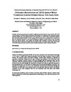
milliseconds or less. However, this time window may be decisive for the stability of the conventional generators connected to the grid and consequently for the whole system. In this regard, the dynamic response of the voltage support by the power generation units (PGU) is a very important issue. The new German renewable energy law (Erneuerbare Energien-Gesetz, EEG) includes new regulations concerning ancillary services [3], which address this subject by specifying timing rules for the system response to grid faults. These rules are based on the diagrams in fig. 1 and fig. 2. Fig. 1 shows the voltage control characteristic that specifies the reactive current set-point depending on the depth of the voltage drop. The controller may include a deadband of up to ±0.1 p.u. and has a setting range for the gain of 0...10 p.u. with a default value of 2 p.u.. To allow the controller also to react to small voltage deviations and to speed up the response a continuous voltage control can be favorable. The maximum available reactive current support of the generation unit for symmetrical faults must not be below 1 p.u.. ΔIr k= ΔIr/ ΔU default: k=2.0 p.u. setting range: k=0.0-10.0 p.u.
I. INTRODUCTION
ith the strong increase in renewable energy generation during the last years, especially in the wind energy sector, new grid codes have been released, stipulating particular requirements concerning grid support during steadystate operation and grid faults. During grid faults the reactive current control of the wind turbines must be used to support the grid voltage [1,2]. With modern protection devices the fault durations are normally in a range of some hundred
C. Feltes is with the University Duisburg-Essen, 47057 Duisburg, Germany, (e-mail:
[email protected]). S. Engelhardt is with Woodward SEG GmbH & Co. KG, 47906 Kempen, Germany, (e-mail:
[email protected]). J. Kretschmann is with Woodward SEG GmbH & Co. KG, 47906 Kempen, Germany, (e-mail:
[email protected]). J. Fortmann is with REpower Systems AG, 22768 Rendsburg, Germany, (email:
[email protected]). I. Erlich is with the University Duisburg-Essen, 47057 Duisburg, Germany, (e-mail:
[email protected]).
978-1-4244-8357-0/10/$26.00 ©2010 IEEE
ΔU
-0.1 0.1
Fig. 1. Required characteristic of voltage control in the new German EEG Voltage Deviation ΔU Reactive Current Deviation ΔIr
tolerance band
settling time < 60ms
rise time < 30ms
Step change in voltage Step response of reactive current Ir
time
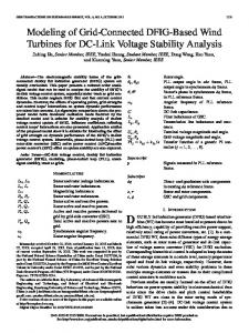
Fig. 2. New requirement in the German EEG concerning the timing of voltage controller response to grid faults
2
Fig. 2 shows the timing requirements, which stipulate a rise time of less than 30ms and a settling time of less than 60ms considering a tolerance band between +20% and -10% of the nominal current around the set-point. Both characteristics refer to the positive sequence quantities. While wind turbines equipped with full-size converters can fulfill these rules with moderate efforts due to their fast decoupled converter control, DFIG-based wind turbines with their grid connected generators are facing a new big challenge, which requires a dedicated control. This paper shows an extended control approach that deals with a highly dynamic response to grid faults similar to that of the full-size converter. Section II describes the recommended procedure for testing and validating the system response to grid faults. Section III gives an overview about the state of the art DFIG configuration and control and introduces a new FRT control. In section IV simulation results are shown proving the good performance of the new control compared to the standard control. Section V finally gives a conclusion.
According to [4] and [5], FRT – tests should be performed using the measurement setup described in Fig. 3. A PGU is connected to the grid through a testing device. The testing device is designed to reduce the voltage at the PGU to a specified level within a very short period of time. During normal operation, switch S1 is closed and switch S2 is open. In order to reduce the impact of activating impedance Z2 on the grid, in a first step switch S1 is opened. This connects the series impedance Z1 in line with the PGU. After the transients have decayed, switch S2 is closed and the short circuit impedance Z2 is connected in parallel to the PGU. This causes a voltage dip at the PGU. After 150..2000 ms depending on the tests required, switch S2 is opened again. The voltage at the PGU then recovers. A short time later, switch S1 is closed, and normal operation is resumed. By using different impedances in the three phases also unsymmetrical faults can be tested. S1 ZG PGU
MP2
Z1
UG
Z2
MP3 Transformer (optional)
S2 Grid
Testing device
u k ,sin =
2 t uk (t ) sin( 2πf1t ) dt T t −∫T
with k = a, b, c
[ [
] ]
(1)
1 2ua ,cos − ub,cos − uc ,cos − 3 (uc ,sin − ub,sin ) 6 1 u1,sin = 2ua ,sin − ub,sin − uc ,sin − 3 (ub,cos − uc ,cos ) 6 p1 = u1,cos ⋅ i1,cos + u1,sin ⋅ i1,sin u1,cos =
q1 = u1,cos ⋅ i1,sin − u1,sin ⋅ i1,cos
The positive sequence current components i1,cos and i1,sin
II. VERIFICATION PROCEDURE
MP1
To verify the system response due to the aforementioned requirements, the measurement data must be further processed to obtain the positive sequence quantities of voltages, active and reactive power and current. Various methods can be utilized to calculate the positive sequence components dealing with different dynamic performance and accuracy. According to [4] the positive sequence components can be calculated by: 2 t u k ,cos = ∫ uk (t ) cos(2πf1t ) dt T t −T
PGU
Fig. 3. Setup to measure the effect of voltage dips on a power generation unit, for example a wind turbine
A. Required Measurements and Data Processing Three phase measurements of voltages and currents must be performed at least at the measurement points MP1 and MP2. Measurements at MP2 describe the behavior of the PGU at its terminals. MP1 is necessary to calculate the data of the grid representation needed for simulations. An additional measurement point MP3 is proposed for PGU connected at low voltage.
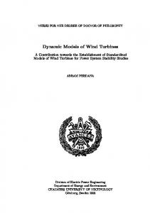
can be calculated by the same rules like the voltage components u1,cos and u1,sin . The integrations over one period of the fundamental frequency result in a considerable delay in the processed data. This complicates the fulfillment of the timing requirements. To compensate this effect in the verification procedure, also the voltage deviation could be processed with this method and the rise and settling time could be evaluated in reference to this filtered signal. III. DFIG BASED WIND TURBINES The DFIG is the most widely used generator system in modern wind turbines, since with its partial rated frequency converter in the rotor circuit it combines high flexibility with moderate costs. Fig. 4 shows the system configuration of a common DFIG-based wind turbine. The main components of the WT are: • Rotor blades • Gearbox (GB) • Slip-ring induction generator (SRIG) • Machine-side converter (MSC) • Line-side converter (LSC) • Machine transformer (Tr) • Filter (Filt) for reduction of switching harmonics • Rotor-crowbar (CR) and chopper (CH) for converter protection The main parts of the DFIG system are the Slip Ring Induction Generator (SRIG) with three-phase stator and rotor windings and the back-to-back PWM converter. The converter uses self-commutated IGBT switches and allows operation in all four quadrants. It is connected between the rotor circuit of the generator and the grid. The MSC operates at slip frequency and controls active and reactive power at the generator stator terminals. The LSC maintains the DC voltage and feeds the rotor power into the grid [6]. The direction of the power flow through the converter depends on the
3
operating point of the generator. In sub-synchronous operation, the power flow is directed from the grid into the rotor circuit, while the power flow direction reverses in supersynchronous mode. Since the converter allows decoupled control of active and reactive power, the LSC can also be used for voltage support through reactive current in-feed in steadystate and during grid faults [7]. The distribution of reactive power flow between stator and LSC can be optimized for minimization of loss and/or thermal loads. Normally, during steady-state operation the LSC only provides a small reactive current contribution. However, during grid faults the current capacity of the LSC is fully used to support the grid, because the response of LSC is faster than that of MSC. U_Grid U_DC U_Stator I_LSC I_Grid I_Rotor I_Stator
Controller
CH U_DC CR
MSC I_Rotor
I_LSC
LSC
GB SRIG
I_Stator
U_Stator
Filt
Tr
I_Grid U_Grid
Fig. 4 DFIG-based wind turbine, main system components and measured quantities for converter control
To guarantee the secure Fault Ride-Through (FRT) capability of the DFIG, the protection devices crowbar and chopper are indispensable [8]. When a grid fault occurs, the voltage drop at the terminal can lead to high DC currents in the generator stator winding. This current component appears as AC current with high peak values on the rotor side, resulting in an abrupt charging of the DC circuit. The ensuing overvoltage would, without protection devices, lead to the destruction of the DC capacitors due to overvoltage. The task of the DC chopper and the AC crowbar is to limit the DC voltage to an acceptable level, by different means. The DC chopper uses an IGBT switch to short-circuit the DC circuit through a braking resistor and thus to dissipate the waste energy that cannot be fed to the grid by the LSC. This method allows a continuous control of the generator currents, but requires additional IGBT switches and braking resistors. The AC crowbar uses thyristor valves to short circuit the rotor through the crowbar resistors, which constitute three resistors in star or delta connection. On the one hand, this method is cheaper and provides a reliable protection for the converter, since it is decoupled from the rotor circuit during crowbar ignition. On the other hand, for the duration of crowbar ignition (approx. 100…120 ms) the generator control is lost and the generator acts as a normal induction generator, which consumes reactive power. From grid point of view, this is not acceptable. In modern DFIG systems a compromise between
the size of the crowbar and the chopper is struck. For example, it is possible to design the chopper in such a way that the crowbar is not activated except during internal faults. A. DFIG control options Since the DFIG control is based on a fast IGBT converter, it offers several control options during steady state operation and grid faults. In steady state, it primarily controls the generator speed in accordance with a specified tracking characteristic to optimize the power output from the wind turbine. The reactive power channel can be used to control the grid voltage or follow instructions of the dispatcher like power factor or reactive power setpoints [9]. During grid faults the reactive power control of both MSC and LSC can be used to support the grid through reactive current in-feed. The control structure of the DFIG-based wind turbines to be used in this study is based on a feed forward decoupled current control for MSC and LSC. The complete structure has been shown in details in previous papers [7,10]. Here, the focus is limited to the outer control loops considering continuous voltage control as introduced in [11]. The outer LSC control loop (Fig. 5) includes a DC voltage controller in the d-axis current path and a nonlinear AC voltage controller realized through a lookup table in the q-axis path. This controller is configured to deal with optimal current distribution between LSC and MSC in steady-state as well as fast voltage support during grid faults. However, its output current is limited due to the thermal limits of the LSC. The outer MSC loop (Fig. 6) includes the active power and AC voltage control of the generator. The power and voltage setpoints are transformed to rotor current setpoints and fed forward to the MSC current controllers [10]. In the q-axis path, the local voltage controller of the generator is implemented to support the grid voltage during steady state and faults. The voltage setpoint u ref is provided by a supervisory wind farm controller and transferred to the WT via a communication link. The wind farm controller can be configured either to control voltage, power factor or reactive power at the PCC [11]. In this WT control strategy two separate voltage controllers are used for the voltage support. The distribution of reactive current between LSC and MSC during faults is determined by the setting of the LSC voltage controller. By considering the ∠us in the MSC feedback signal of the LSC q-axis current iLSCq controller it is ensured that the total reactive current is set to the output value of the MSC voltage controller, whose characteristic is set according to the requirements in Fig. 1. The LSC is much faster compared to the MSC and due to its sufficient voltage setting range it nearly stays unaffected by grid faults. But its current limits only allow the LSC to participate with up to approx. 50% of the DFIG nominal current. However, the MSC current limits are much higher and allow it to take the major part of the voltage support. But since the generator stator is connected directly to the grid, the MSC is strongly affected by grid faults and the voltage setting range is not sufficient to compensate the short circuit currents that are induced from the stator side. These short circuit current components also affect the MSC controller response and limit
4
the dynamic performance. Additionally, high overcurrents may lead to a blocking of the MSC, which further increases the response time. This delay can be limited by optimizing the blocking-time of the IGBT gate signals. u DC _ ref
-
u DC
⎛ 1 ⎞ ⎟ K P ⎜⎜1 + pTI ⎟⎠ ⎝
-
÷
pR uG
∠ug iLSCd _ ref
LSC lookup table
f ( Δu ) Lag compensator
uref
∠ug iLSCq _ ref
f (Δu )
-
1 1 + pT1
÷
∠us iSd _ ref
−
-
u ref
u
KVC -
∠us iLSCq
−
xS xh
-
⎛ 1 ⎞ ⎟ K P ⎜⎜1 + pTI ⎟⎠ ⎝
-
÷
pR
∠ug iLSCd _ ref
magnitude limitation with active current priority
∠u S i Rd _ ref
Fig. 8 Modified outer LSC control loop with DC voltage controller
∠u S i Rq _ ref
-
∠ug iLSCq _ ref
∠ug iLSCq _ ref *
magnitude limiter ∠us iSq _ ref
∠us iLSCq _ ref *
uG
xS xh
∠us iLSCd
uS
-
Fig. 7 Extended voltage control for increased dynamic performance
u DC
Fig. 5 Outer LSC control loop with DC and AC voltage controller
pWT _ ref
f 0 = 50 Hz
iS∠1usq
u DC _ ref
|u|
∠us iSq _ ref *
|u|
magnitude limitation with active current priority
LSC lookup table
uref
1 + pT2 1 + pT3
KVC
-
-
1 xh
pWT _ ref
uS
uS Fig. 6 Outer MSC control loop with active power and AC voltage control
To guarantee that the requirements in Fig. 2 can be met with a certain margin, the control structure needs to be modified to reduce the controller response time considering the strengths and weaknesses of both converters. Fig. 7..Fig. 9 show a dedicated control strategy especially designed to meet the new requirements. Instead of using two separate voltage controllers, one central voltage controller is coordinating the voltage support during steady state and grid faults (Fig. 7). The reactive current distribution between MSC and LSC is achieved by adjusting the stator current setpoint instead of increasing the LSC reactive current directly. This is done based on the same lookup table as in Fig. 5. The task of the LSC is to compensate the error between total reactive current setpoint and measured stator reactive current. To avoid that the LSC feeds in DC or negative sequence currents in consequence to a disturbed setpoint, the q-axis component of the positive sequence stator current is filtered with a 50Hz band-stop filter before it is used in the LSC setpoint calculation. To reduce the response time of the MSC control, a lag compensator is introduced, leading to an overshoot in the MSC q-axis current setpoint in consequence to a considerable voltage drop.
∠us iSq _ ref *
÷
1 1 + pT1
∠us iSd _ ref
−
-
xS xh
∠us iLSCd
∠u S i Rd _ ref
magnitude limiter
−
xS xh
∠u S iRq _ ref
1 xh
uS Fig. 9 Modified outer MSC control loop with active power and stator reactive current control
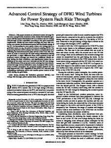
IV. SIMULATION The simulations presented here have been carried out with MATLAB/Simulink with SimPowerSystems Toolbox in the time domain based on instantaneous values. The evaluation of the controller response is based on the processing rules from section II.A. Fig. 10 and Fig. 11 show simulation results for a threephase fault with a resulting voltage drop to approx. 40% of the nominal voltage at the MV side of the WT transformer. The simulations are based on the test configuration described in section II. In the scenario in Fig. 10 the conventional FRT control (Fig. 5 and Fig. 6) is used and configured for full LSC voltage support. In response to the voltage drop the DFIG
5 WEA Voltages (p.u.)
1.5
Ua Ub Uc
Voltage (p.u.)
1 0.5 0 -0.5 -1 -1.5
WEA Active and Reactive Current (p.u.)
3.5 3
Ia Ir
Current (p.u.)
2.5 2 1.5 1 0.5 0 -0.5 -1
Stator Active and Reactive Current (p.u.)
3
Isa Isr
2.5 2 Current (p.u.)
stator currents contain the typical DC components leading to peak values of approx. 2.3 p.u. of active and 2.0 p.u. of reactive current. The LSC feeds in full reactive current of approx. 0.5 p.u.. The evaluation of the reactive current response shows a small rise time of approx. 11 ms, but a settling time of approx. 58 ms, which is extremely close to the upper time limit from the requirements. With the enhanced FRT control the first stator reactive current peak is slightly higher compared to the first scenario, but the fast LSC control reduces the total reactive current peak to approx. 2 p.u.. In the response evaluation this leads to a rise time that is slightly higher (approx. 13 ms). However, the overshoot is smaller and the reactive current response faster enters and remains within the deadband. The settling time of approx. 42 ms is far below the stipulated limit. The test equipment from section II is using large reactances in the voltage divider. This only can represent weak grid connections. Fig. 12 shows the simulation results for a stronger grid connection with a voltage sag to 20% of the nominal voltage at the MV terminals of the WT transformer. This deep voltage sag leads to higher peak currents in the generator, which result in an overcurrent blocking of the MSC. This is a special challenge for the DFIG, since the control is disabled during the blocking time and the rotor flux is reduced, since the rotor current commutates to the freewheeling diodes of the MSC and is dissipated in the chopper resistance. I.e., the control has to increase the rotor flux again after deblocking and consequently there is less time to track the reactive current setpoint. Nevertheless, with the new control a rise time of approx. 10 ms and a settling time of approx. 42 ms can be reached.
1.5 1 0.5 0 -0.5 -1
LSC Active and Reactive Current (p.u.)
1
Ilsca Ilscr
0.8
V. CONCLUSION Current (p.u.)
0.4 0.2 0 -0.2 -0.4 -0.6 -0.8
WEA Reactive Current Response (p.u.) 1.4 1.2 1 Current (p.u.)
This paper has introduced the new German grid code requirements concerning voltage support during grid faults and the corresponding timing requirements. A new voltage control for DFIG based WTs has been proposed, especially designed to meet the new requirements. Simulations have been performed to show the good performance of this control. With the new control the DFIG is capable of supplying considerable reactive current immediately after the voltage drop occurs and the positive sequence reactive current enters and remains within the specified tolerance band very quickly. Even for deep voltage sags that lead to a short over-current blocking of the MSC, the timing requirements can still be fulfilled. I.e. the DFIG is able to give a fast voltage support during three-phase faults and thus it can considerably participate in increasing the system stability. Further research must be done to implement and test this approach also for unbalanced faults in coordination with a negative sequence control to achieve optimal voltage support also in these cases. Finally, in the practical implementation some additional phenomena may occur, which are not considered in the simulations like measurement errors through saturation of current transformers and saturation of the reactors of the voltage divider. These may reduce the performance and lead to higher rise and settling times.
0.6
0.8 0.6 Ir_ref 0.4
Ir_WEA
0.2 0 -0.2 -0.02
-0.01
0
0.01
0.02
0.03
0.04
0.05
0.06
0.07
0.08
0.09
0.1
time (s)
Fig. 10 Simulation results with conventional FRT control for a three-phase symmetrical fault with a resulting voltage drop to approx. 40% of the nominal voltage on the MV side of the WT transformer. All quantities shown are measured at the low voltage side.
6 WEA Voltages (p.u.)
1.5
WEA Voltages (p.u.)
1.5
Ua
Ua Ub Uc
0.5 0 -0.5
-0.5
-1.5
-1.5
WEA Active and Reactive Current (p.u.)
WEA Active and Reactive Current (p.u.)
3.5
3
Ia
2.5
Ir
3
Ia
2.5
Ir
2
2
Current (p.u.)
Current (p.u.)
0
-1
1.5 1 0.5
1.5 1 0.5 0 -0.5
0
-1
-0.5
-1.5
-1
-2
Stator Active and Reactive Current (p.u.)
3
Stator Active and Reactive Current (p.u.)
3.5 3
2.5
Isa Isr
1.5 1 0.5
Isa
2.5
Isr
2 Current (p.u.)
2 Current (p.u.)
0.5
-1
3.5
Ub Uc
1
Voltage (p.u.)
Voltage (p.u.)
1
1.5 1 0.5 0 -0.5
0
-1
-0.5
-1.5
-1
-2
LSC Active and Reactive Current (p.u.)
1
LSC Active and Reactive Current (p.u.)
1
Ilsca
Ilsca
0.8
Ilscr
Ilscr Current (p.u.)
Current (p.u.)
0.6 0.4 0.2 0
0.5
0
-0.2 -0.4 -0.5
-0.6
WEA Reactive Current Response (p.u.)
WEA Reactive Current Response (p.u.) 1.4
1.4
1.2
1.2
1 Current (p.u.)
Current (p.u.)
1 0.8 0.6
Ir_ref Ir_WEA
0.4
0.6 Ir_ref 0.4
Ir_WEA
0.2
0.2
0
0 -0.2 -0.02
0.8
-0.01
0
0.01
0.02
0.03
0.04
0.05
0.06
0.07
0.08
0.09
0.1
time (s)
Fig. 11 Simulation results with enhanced FRT control for a three-phase symmetrical fault with a resulting voltage drop to approx. 40% of the nominal voltage on the MV side of the WT transformer. All quantities shown are measured at the low voltage side.
-0.2 -0.02
-0.01
0
0.01
0.02
0.03
0.04
0.05
0.06
0.07
0.08
0.09
0.1
time (s)
Fig. 12 Simulation results with enhanced FRT control for a three-phase symmetrical fault with a resulting voltage drop to approx. 20% of the nominal voltage on the MV side of the WT transformer. The deep voltage sag results in overcurrent blocking of the MSC. All quantities shown are measured at the low voltage side.
7
VI. REFERENCES [1]
VDN: Transmission Code 2007, Netz- und Systemregeln der deutschen Übertragungsnetzbetreiber, Version 1.1, August 2007 [2] BDEW: Technische Richtlinie Erzeugungsanlagen am Mittelspannungsnetz, Juni 2008 [3] Verordnung zu Systemdienstleistungen durch Windenergieanlagen (Systemdienstleistungsverordnung – SDLWindV), BMU, Germany27.05.2009 [4] IEC: IEC 61400-21 ed. 2, Wind turbine generator systems – Part 21: Measurement and assessment of power quality characteristics of grid connected wind turbines [5] FGW: Technical Guidelines for Power Generating Units. Part 4 Demands on Modeling and Validating Simulation Models of the Electrical Characteristics of Power generation Units and Systems. Revision 4, September 15th, 2009 [6] R. Pena, J. C. Clare, G. M. Asher, “Doubly fed induction generator using back-to-back PWM converters and its application to variable-speed wind-energy generation”, in Proc. 1996 IEE Electric Power Applications [7] Feltes, C.; Engelhardt, S.; Kretschmann, J.; Fortmann, J.; Koch, F.; Erlich, I.: „High voltage ride-through of DFIG-based wind turbines”, Power and Energy Society General Meeting, 2008 IEEE, 20-24 July 2008 Page(s):1 – 8 [8] I. Erlich, H. Wrede, C. Feltes, „Dynamic Behavior of DFIG-Based Wind Turbines during Grid Faults”, IEEJ Transactions on Industry Applications, April 2008 Volume 128-D Number 4 , Page(s):909 – 919 [9] M. Wilch, I. Erlich, Istvan; J. Fortmann, F. Koch: “A novel centralised wind farm controller utilising voltage control capability of wind turbines”, PSCC Power System Computation Conference 2008, July 2008, Glasgow [10] I. Erlich, J. Kretschmann, J. Fortmann, et al., “Modeling of Wind Turbines based on Doubly-Fed Induction Generators for Power System Stability Studies”, Modeling of Wind Turbines Based on Doubly-Fed Induction Generators for Power System Stability Studies, IEEE Transactions on Power Systems, Volume 22, Issue 3, Aug. 2007 Page(s):909 – 919 [11] J. Fortmann, M. Wilch, I. Erlich, F. Koch: “A novel centralised wind farm controller utilising voltage control capability of wind turbines”, PSCC Power System Computation Conference 2008, July 2008, Glasgow
VII. BIOGRAPHIES Christian Feltes (1979) received his Dipl.-Ing. degree in electrical engineering from University of DuisburgEssen/Germany in 2005. Since January 2006 he is doing his Ph.D. studies in the Department of Electrical Power Systems at the same University. His research interests are focused on wind energy generation, control, integration and dynamic interaction with electrical grid. He is student member of IEEE.
Stephan Engelhardt (1967) received his Dipl.-Ing. degree in electrical engineering from the University Hannover, Germany, in 1997. Since 1997 he is with Woodward SEG GmbH & Co. KG, Kempen/Germany, presently head of the group Converter Technology and responsible for system designs and simulations, control strategies and patents. He is a member of IEEE.
Jörg Kretschmann (1958) received his Dipl.-Ing. degree in electrical engineering from the Technical University Berlin, Germany, in 1986. In the period of 1986 to 1988 he worked for engineering department of AEG-Kanis in Essen, manufacturing of synchronous generators up to 200 MVA. Since 1988 he is with Woodward SEG GmbH & Co. KG, Kempen/Germany, as a designing engineer for speed-variable applications: uninterruptible power supply, shaft alternators, DFIG for wind turbines. His main field is simulation of power converter systems, design of power components, passive grid-filter. Jens Fortmann (1966) received his Dipl.-Ing. degree in electrical engineering from the Technical University Berlin, Germany, in 1996. From 1995 to 2002 he worked on the simulation of the electrical system and the control design of variable speed wind turbines at the German wind turbine manufacturers Suedwind and Nordex Energy. Since 2002 he is with REpower Systems AG, Germany as project manager for the simulation and implementation of new technologies for improved grid compatibility of wind turbines like voltage control and ridethrough of grid faults. He is member of IEEE. Istvan Erlich (1953) received his Dipl.-Ing. degree in electrical engineering from the University of Dresden/Germany in 1976. After his studies, he worked in Hungary in the field of electrical distribution networks. From 1979 to 1991, he joined the Department of Electrical Power Systems of the University of Dresden again, where he received his PhD degree in 1983. In the period of 1991 to 1998, he worked with the consulting company EAB in Berlin and the Fraunhofer Institute IITB Dresden respectively. During this time, he also had a teaching assignment at the University of Dresden. Since 1998, he is Professor and head of the Institute of Electrical Power Systems at the University of Duisburg-Essen/Germany. His major scientific interest is focused on power system stability and control, modelling and simulation of power system dynamics including intelligent system applications. He is a member of VDE and senior member of IEEE.