Feb 26, 1995 - Brian Wyvill, Jules Bloomenthal, Geo Wyvill, Jim Blinn, Alyn Rock- wood, Thad Bier, and Jim Cleck. Course Notes. SIGGRAPH '90, Course.
Controlled Blending for Implicit Surfaces using a Graph Andrew Guy and Brian Wyvill February 26, 1995 Department of Computer Science, University of Calgary 2500 University Dr. NW, Calgary T2N 1N4 Canada
Abstract
Automatic blending between surfaces surrounding skeletal elements has been cited as one of the chief advantages of using implicit surface modeling techniques. However, achieving control so that blending occurs only when it is desirable is a di�cult problem. In this paper we look at using a graph to specify the blending between objects. We propose a new method which produces a C(0) continuous function. Keywords: implicit surfaces, blending, skeletal modeling.
1 Introduction [Blinn 82] rst used implicit surfaces to model electron density elds and suggested their use as a more general modeling primitive. This idea was taken up by [Wyvill 86] and [Nishimura 85] and developed into a useful modeling tool. A model is de ned as being composed of Skeletal Elements, a scalar eld is constructed composed of such elements. The model is an iso-surface in the scalar eld and has been referred to as an implicit surface, (see [Bloomentha 90]). One of the important and useful properties of implicit surfaces are their ability to blend together surfaces formed from individual skeletal elements. In earlier systems, to nd the value of a point in the scalar eld (the fit implicit value or eld value), contributions from neighbouring skeletal elements are summed, the contributions weighted by a distance function. Thus blending is achieved, however it is global in nature which leads to the problem that skeletal elements will blend whenever they are close enough to each other. This can be undesirable, for example, when attempting to model a hand the ngers must blend with the palm but not with each other (see [Bloomentha 90]). Methods for controlling the type or `hardness' of blending are give in [Kacic-Ales 91]. However, control is not only required over how skeletal elements blend but also over which pairs of elements are allowed to blend with each other. In [Wyvill 92] a graph structure was suggested to control which elements blend together. Marie-Paule Gascuel describes a method which produces precise contact surfaces between non-blending objects. (see [Gascuel 93] ) This involves a `contracting' factor: ( ) = min(Iso , ( ) 0) where Iso is the value of the iso-surface, ( ) is the eld value from the skeletal element. Then min() function is used as the e�ect is only required when the elements would otherwise intersect. The eld value for two skeletal elements at a point would then be: ct p
f p ;
f p
p
( ) = l ( ) + ( s ( ))
F p
f
p
1
ct f
p
where l ( ) is larger of the two eld values at and s ( ) the smaller. [Opalach 93] used this technique together with a skeleton composed of links and joints to construct models. However both these earlier methods do not guarantee C(0) continuity. In this paper we present a variation on this method which moreover also produces a C(0) continuous function. f
p
p
f
p
2 Terminology In this paper we use the term `object' for a primitive (eg ellipse) or a group of primitives. The groupings can be the basic summation group widely used, or a maximum or minimum function which are similar to CSG intersection and union. [Gascuel 93] can be thought of as a group in which the objects do not blend and are deformed when they come in contact | we refer to this as a precise-contact-modeling (pcm) group. In this paper we show how groups can be used as a partial solution to the blending problem and then explore groupings that use a graph to specify which objects blend.
3 Use of Groups The problem of blending and non-blending objects can be partially solved by using an appropriate structured set of groups. Figure 1 shows how to arrange the objects which make up a hand so that the ngers will not blend with one another. The palm of the hand is made up of two primitives, a super-ellipse and a cylinder. Each nger is composed of three cylinders. The ngers are grouped together with a `pcm' group. This ensures that the ngers don't blend. The ngers group and the primitives that form the palm of the hand are then grouped in the normal summation group. This has the e�ect that the ngers do not blend with each other but they do blend with the palm. Figure 1 shows the resulting model. However, if the st is examined in more detail it can be seen that the tips of the ngers also blend with the palm. This method of specifying blending and non-blending objects cannot deal with properly with loops in the topology. One end of the nger must blend with the palm but not the other. Also this is a counter-intuitive method of controlling the blending | objects which don't blend are grouped together. A more general method is required and this leads us to using a blend graph.
4 Blend Graph A graph is used to specify the blending between objects. Each object in the group is represented by a node in the graph. Arcs connect objects which blend. Figure 2 show a section through the eld generated by a chain of four spheres, each blending with its neighbors. The function which de nes this surface is speci ed in terms of the blend graph and the eld values from each of the objects in the group. For each object a value i is calculated: i = i + mb +
g
f
f
Xn f ( j) j =0
ct f
i
j
j
6=
i;
j
6=
g
mb g
f
where: is the number of objects. j is the eld value of object . mb is the maximum eld value from the objects that blend with . ( ) is the contraction factor (see above) and causes objects to deform against each other rather than blending. The eld value for the group is then the maximum of the i 's. The use of maximum in such a case was suggested by Thad Bier in [Wyvill 90]. n
f
j
f
i
ct f
G
g
2
S P
F
H
F
S - sumation group F - finger P - pcm group H - rest of hand
Figure 1: Groups used to model a st and the resulting image
Figure 2: Chain of four spheres
3
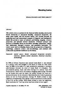
Figure 3: a. Primitives used to generate the hand, b. Slice through the eld generated
Figure 4: Image of the hand The reason for only using the maximum of the objects that blend with can be seen if we look at a chain of three spheres, labeling them a,b,c. If we take all the objects that blend with into account the value of will always be a + b + c as this will always be larger of the three values. This of course is identical to the simple summation usually used and will lead to undesired blending between a and c. By only taking the maximum we get the same e�ect that was produced by the use of groups in the section above. It is important the function is continuous if 0::n are continuous. The functions and max preserve continuity so the function produced also preserves continuity. However the function is not C(1), this will produce discontinuities in the normals. i
i
G
f
G
f
f
f
ct
5 Model of a hand Figure 3a shows the objects that make up a simple model of the hand consisting of three ellipses for each of the ngers and ve ellipses for the palm. The lines show the blending graph that was used. A slice through the eld produced is shown in gure 3b. Figures 4 & 5 show the hand in various positions. The problem of normal discontinuities is shown in gure 6, the hand is numbered to show which of the objects was predominate at each point when calculating the eld value. At the boundaries in gure 6, C(1) discontinuities can arise. Comparing gure 6 with gure 5 it can be seen that discontinuities in the normals can be seen at these boundaries on the palm of the hand, although this a�ect is exaggerated by the polygonization used before rendering.
4
Figure 5: Image of the hand
Figure 6: In uence of objects on the eld
5
6 Conclusions This method of combining the eld values from the objects has the desired properties: objects connected in the graph blend with each other; objects that are not connected are deformed against each other and the resulting function is continuous. However the discontinuities in the normals are still a problem and a method that removes these is needed.
References [Blinn 82]
James Blinn. A Generalization of Algebraic Surface Drawing. ACM Transactions on Graphics, 1:235, 1982. [Bloomentha 90] Jules Bloomenthal and Brian Wyvill. Interactive Techniques for Implicit Modeling. Computer Graphics, 24(2):109{116, 1990. [Gascuel 93] Marie-Paule Gascuel. An Implicit Formulation for Precise Contact Modeling Between Flexible Solids. Computer Graphics (Proc. SIGGRAPH 93), pages 313{320, August 1993. [Kacic-Ales 91] Zoran Kacic-Alesic and Brian Wyvill. Controlled Blending of Procedural Implicit Surfaces. Proc. Graphics Interface 1991, pages 236{245, 1991. [Nishimura 85] Hitoshi Nishimura, Makoto Hirai, Toshiyuki Kawai, Toru Kawata, Isao Shirakawa, and Koichi Omura. Object modeling by distribution function and a method of image generation. Trans. IEICE Japan, J68-D(4):718{ 725, 1985. [Opalach 93] Agata Opalach and Steve Maddock. Implicit surfaces: Appearance, blending and consistency. In Fourth Eurographics Workshop on Animation and Simulation, Barcelona, Spain, 1993. [Wyvill 86] Geo� Wyvill, Craig McPheeters, and Brian Wyvill. Data Structure for Soft Objects. The Visual Computer, 2(4):227{234, February 1986. [Wyvill 90] Brian Wyvill, Jules Bloomenthal, Geo� Wyvill, Jim Blinn, Alyn Rockwood, Thad Bier, and Jim Cleck. Course Notes. SIGGRAPH '90, Course #23, Modeling and Animating with Implicit Surfaces, 1990. [Wyvill 92] Brian Wyvill. Warping Implicit Surface for Animation E�ects. Proc. Western Computer Graphics Symposium (SKIGRAPH 92), pages 55{63, 1992.
6