Using Particles to Sample and Control Implicit Surfaces Andrew P. Witkin Paul S. Heckbert Department of Computer Science Carnegie Mellon University
Abstract We present a new particle-based approach to sampling and controlling implicit surfaces. A simple constraint locks a set of particles onto a surface while the particles and the surface move. We use the constraint to make surfaces follow particles, and to make particles follow surfaces. We implement control points for direct manipulation by specifying particle motions, then solving for surface motion that maintains the constraint. For sampling and rendering, we run the constraint in the other direction, creating floater particles that roam freely over the surface. Local repulsion is used to make floaters spread evenly across the surface. By varying the radius of repulsion adaptively, and fissioning or killing particles based on the local density, we can achieve good sampling distributions very rapidly, and maintain them even in the face of rapid and extreme deformations and changes in surface topology. CR Categories: I.3.5 [Computer Graphics]: Computational Geometry and Object Modeling: Curve, surface, solid, and object representations, Physically based modeling; I.3.6 [Computer Graphics]: Methodologies and Techniques: Interaction techniques; G.1.6 [Numerical Analysis]: Optimization: Constrained Optimization. General Terms: algorithms, design. Additional Key Words and Phrases: physically based modeling, constrained optimization, adaptive sampling, interaction.
1
Introduction
Implicit surfaces have proven to be useful for modeling, animation, and visualization. One appeal of implicit models is that new surfaces can be created by adding or otherwise combining the functions that define them, producing a variety of subtle and interesting shape effects. Another is their role in the visualization of volume data. In addition, the implicit representation lends itself to such calculations as ray/surface intersection and inside/outside test. However, implicit surfaces suffer from two serious drawbacks: first, although well suited to ray tracing, they are not easily rendered at interactive speeds, reflecting the underlying problem that it is difficult to sample them systematically. This is particularly a problem if we wish to render time-varying surfaces in real time, which is vital for interactive sculpting. Second, the shapes of implicit surfaces have proven to be more difficult to specify and control than those of their parametric counterparts. Mail to the authors should be addressed to the Department of Computer Science, Carnegie Mellon University, 5000 Forbes Ave, Pittsburgh PA 15213, USA. Email should be addressed to Andrew Witkin as
[email protected], and to Paul Heckbert as
[email protected]. c °1994 ACM. Reprinted from Computer Graphics, Proc. SIGGRPAH ’94.
In this paper, we present a new particle-based approach to sampling and shape control of implicit surfaces that addresses these problems. At the heart of our approach is a simple constraint that locks a collection of particles onto an implicit surface while both the particles and the surface move. We can use the constraint to make the surface follow the particles, or to make the particles follow the surface. Our formulation is differential: we specify and solve for velocities rather than positions, and the behavior of the system is governed by differential equations that integrate these velocities over time. We control surface shape by moving particles interactively, solving for surface motion that keeps the particles on the surface. This technique lets us pin down the surface at some points while interactively dragging others. These particles act as control points for direct manipulation of the surface. For sampling and rendering, we run the constraint in the other direction, creating particles that may roam freely over the surface, but are compelled to follow it as it moves. We call these particles floaters. Our starting point is the idea that uniform sampling density can be achieved by making the particles repel each other. This approach was used by Turk [29] to resample polygon meshes, and by Figueiredo et al. [12] to sample implicit surfaces. Simple repulsion can work quite well for stationary surfaces, but only if a reasonably good initial sampling is available. If largescale non-uniformities exist, convergence can be extremely slow for even moderate sampling densities. We eliminate the need for a good starting point, and dramatically accelerate convergence, by employing an iterative “fissioning” approach, in which we start with a small number of particles and a large radius of repulsion, allow them to equilibrate, then split each particle in two, reducing the radius of repulsion. We repeat the process until the desired sampling density is reached. Each level thus inherits a distribution that is already uniform at large scale, requiring just a few iterations to iron out the local irregularities. Global fissioning still fails to handle surfaces that move and deform, since irregularities can arise after the density becomes high. We introduce a local adaptive repulsion algorithm, in which the repulsion radius and particle birth and death are regulated based on local density. This method is fast enough to maintain good sampling even in the face of rapid and extreme surface motion and deformation. The remainder of the paper is organized as follows: we begin by discussing previous related work. Then we introduce the basic constraint mechanism that attaches particles to surfaces. Next we describe the use of particles for surface shape control. We then explain our adaptive repulsion sampling algorithm. After describing the implementation and results, we conclude with a discussion of future work.
2
Previous Work
penalty methods, however, which lead to stiff differential equations whose solution is generally either slow to repel into a nice pattern, or inaccurate at staying on the surface. Once the particles have reached equilibrium, a polygonization is found using Delaunay triangulation. Their work resembles ours most closely, but our simulation method differs from theirs, and our technique supports interactive control of surfaces and incremental sampling of changing surfaces, while theirs does not.
Related work can be divided into two categories: sampling methods and control methods.
2.1
Sampling Methods
Related research on surface sampling includes both particle-based sampling techniques and polygonization techniques for implicit surfaces. Turk used repelling particles on surfaces to uniformly resample a static surface [28] and to simplify a polygonization by reducing the number of polygons [29]. Hoppe et al. also explored mesh simplification, framing it as an optimization problem with penalties for geometric error, number of samples, and edge length [16]. Their method did not restrict the points to a surface, however, as Turk’s and ours do. Szeliski and Tonnesen used oriented particles to model surfaces [27]. Their technique allowed the user to move the particles interactively, employing short-range repulsion and long-range attraction to keep the particles from clumping or flying apart. The system generated a surface by connecting neighboring particles appropriately, but it did not manipulate a high level representation for a surface, such as a parametric patch or an implicit function, as ours does. The output of their system was a triangulation. Their system bears a superficial resemblance to ours because we both use disks to visualize the surface, but in other respects our techniques are quite different. An implicit surface, also called an iso-surface, is the set of points x that satisfy F(x) = 0. Implicit surfaces are typically defined by starting with simple building block functions and by creating new implicit functions using the sum, min, or max of simpler functions. When the building blocks are polynomials in x, y, and z, the resulting surfaces are called algebraic surfaces, and when the building blocks are spherical Gaussian functions, the surfaces are called blobbies [8], “soft objects”, or “metaballs”. The use of sums of implicit functions allows blend surfaces to be created [24], and the use of min and max yields the union and intersection of solid objects. Rendering an implicit surface is often difficult. If a ray tracer is used, intersecting a ray with an implicit surface reduces to onedimensional root-finding, but this can be very slow for a complex implicit function [8]. To exploit the speed of graphics hardware, we would prefer to render using a z-buffer algorithm. This requires converting the implicit surface into polygons or other parametric surfaces. Most existing methods for polygonizing implicit surfaces subdivide space into a uniform grid of cubical or tetrahedral voxels, sample the function at the vertices of the voxels, and then, for each voxel whose vertices are not all in or all out, generate polygon(s) approximating the surface [33,18,21,10]. This approach is often called the marching cubes algorithm. Improvements on this algorithm use adaptive subdivision based on curvature [9]. Unfortunately, all of these algorithms will miss small surface features if the initial sampling grid is too coarse, except Snyder’s, which uses interval arithmetic to guarantee that the topology of the polygonization matches the topology of the real surface [26]. These polygonization algorithms were designed for static surfaces; to polygonize a changing surface with them would require beginning from scratch each time. The algorithm of Jevans et al. is an exception. It re-polygonizes only those voxels that change [17]. Physically-based approaches to the polygonization of implicit surfaces were pioneered by Figueiredo et al. [12]. One of the two methods they describe starts with particles randomly scattered in 3-D space, subjects them to forces that pull them to the surface (an idea proposed in [11]), and uses repulsion between particles to distribute them uniformly over the surface. Their technique uses
c °1994 ACM
2.2
Control Methods
One of the principal disadvantages of implicit modeling relative to parametric modeling is the difficulty of controlling the shape of an implicit surface [11]. The effect of the parameters of an implicit surface is often non-intuitive. With algebraic surfaces, for instance, it is hard to predict the surface shape given its coefficients. Modeling is further complicated by the global nature of an algebraic surface’s polynomial basis functions, which prevent local shape control. For these reasons and others, piecewise algebraic surfaces have recently become popular [25]. Piecewise algebraic surfaces are typically defined by a weighted sum of Bernstein polynomials over a lattice of tetrahedra. Least squares methods for fitting surfaces to a set of points are available both for standard algebraic surfaces [22] and for piecewise algebraic surfaces [1]. Pratt’s algorithm can fit a surface with m parameters to n points (n > m) in time O((n +m)m 2 ). These methods are limited to algebraic surfaces, however. Blobby models employ local basis functions, so they are often more intuitive to work with than algebraic surfaces [8]. In an interactive blobby modeling system, a user might use dials or sliders to adjust the position and radius of each blobby center [7], but arriving at a desired surface is a matter of guesswork, and the real time display is typically just a wireframe, with a higher quality rendering requiring off-line ray tracing or polygonization. Some recent work has fit blobby models to a set of surface points, but the method is quite slow, one example requiring days of computer time to fit 2900 control points using 1200 parameters [20]. Direct manipulation of a blobby surface at interactive speeds has remained an open problem. The differential methods we use to constrain the motion of particles and surfaces are rooted in classical mechanics (see, e.g. [15] for a discussion of mechanical constraints and constraint forces) and are closely related to constraint methods used in physically based modeling for computer graphics [5,2,3,32,31,4]. Allied methods have also been used for interactive geometric modeling [30,14].
3
The Particle/Surface Constraint
In this section we derive the basic machinery that allows us to attach moving particles to moving surfaces. First we derive a basic constraint on particle and surface velocities that establishes, then maintains contact as the system evolves over time. We then pose two related problems: solve for particle velocities given time derivatives of the surface parameters, and solve for surface derivatives given particle velocities. Since the problem will generally be underconstrained, we express it as a constrained optimization. Notation: We use boldface to denote vectors, and italics for scalars. Subscripts denote partial differentiation. Superscript i or j denote the ith or jth member of a collection of objects. E.g. pi is the ith in a collection of vectors, and Fx is the derivative of scalar F with respect to vector x, hence a vector. Superscripts other than 2 i or j have their usual meaning as exponents, e.g. |x − c|2 or e−x . ˙ denotes a derivative with respect to time. A dot, as in q,
2
Computer Graphics, Proc. SIGGRPAH ’94.
3.1
The Basic Constraint
The classical method of Lagrange multipliers [13] solves constrained optimization problems by adding to the gradient of the objective a linear combination of constraint gradients, with unknown coefficients. One then solves simultaneously for the original unknowns, and for the coefficients. In the case of linear constraints and a quadratic objective, this is a linear problem. ˙ and q˙ The two problems we wish to solve—obtaining p˙ i given q, given p˙ i —seek to minimize the same objective subject to the same constraints, differing only in regard to the knowns and unknowns. Even so, the solutions will turn out to be quite different because of ˙ We next consider the structure of C j ’s dependencies on p˙ i and q. each problem in turn.
We represent the moving implicit surface by F(x, q(t)) = 0, where x is position in space, and q(t) is a vector of m time-varying shape parameters. For example, an implicit sphere could be defined by F = |x − c|2 − r 2 , with center c and radius r . The parameter vector q would then be the 4-vector [cx , c y , cz , r ]. The condition that a collection of n moving particles lie on the surface is F(pi (t), q(t)) = 0, 1 ≤ i ≤ n, (1) where pi (t) is the trajectory of the ith particle. In order for this condition to be met from some initial time t0 onward, it suffices that equation 1 is satisfied at t0 , and that the time derivative F˙ = 0 thereafter. Since we want to manipulate velocities rather than positions, we obtain an expression for F˙ using the chain rule: ˙ F˙ i = Fxi · p˙ i + Fqi · q,
3.3
(2)
˙ Fx , and Fq evaluated at pi . By where F˙ i , Fxi , and Fqi denote F, i ˙ setting F to zero in equation 2, we obtain n linear constraints on the ˙ In principle, if we began with a valid state and ensured p˙ i s and on q. that these conditions were met at every instant thereafter, we would be guaranteed that the particles remained on the surface. In practice, we might not have valid initial conditions, and numerical integration errors would cause drift over time. We cure these problems using a feedback term [6], setting F˙ i = −φ F i , where φ is a feedback constant. This yields the set of n linear constraint equations ˙ = Fxi · p˙ i + Fqi · q˙ + φ F i = 0 C i (pi , p˙ i , q, q)
3.2
Floaters
In solving for the p˙ i ’s, the requirement that the gradient of the objective be a linear combination of the constraint gradients is expressed by G p˙ i +
X
λ j C j p˙ i = p˙ i − P i + λi Fxi = 0
(4)
j
for some value of the unknown coefficients λi . The summation over j drops out because C j cannot depend on p˙ i unless i = j. In addition we require that the constraints be met, i.e. that C i = 0, 1 ≤ i ≤ n. Equation 4 allows us to express the p˙ i ’s in terms of the unknown λi ’s. Substituting for p˙ i in equation 3 gives
(3)
Fxi · (P i − λi Fxi ) + Fq · q˙ + φ F i = 0. We may solve for each λi independently. Doing so yields
Constrained Optimization
We employ these constraints in two ways: first, in order to use particles to move the surface, we solve for q˙ given the p˙ i ’s. Second, to use mutually repelling particles to sample the surface, we solve ˙ In either case, we generally wish to solve unfor the p˙ i ’s given q. derconstrained systems. To do so we minimize a quadratic function ˙ subject to the constraints. The objective function we of p˙ i and q, use here is
λi =
Fxi · P i + Fq · q˙ + φ F i . Fxi · Fxi
Substituting into equation 4 yields F i · P i + Fq · q˙ + φ F i i p˙ i = P i − x Fx Fxi · Fxi
1X i 1 |p˙ − P i |2 + |q˙ − Q|2 , 2 i=1 2
(5)
n
G=
which is the particle velocity that solves the constrained optimization problem. Notice that in the case that the surface is not moving and the constraints are met, so that F i = 0 and q˙ = 0, this reduces to
where P i and Q are known desired values for p˙ i and q˙ respectively.1 These desired values can be used in a variety of ways. Setting P i to zero minimizes particle velocities. Setting Q to zero minimizes the surface’s parametric time derivative. In unconstrained optimization we require that the gradient of the objective function vanish. At a constrained minimum, we require instead that the gradient of the objective function be a linear combination of the gradients of the constraint functions [13]. This condition ensures that no further local improvement can be made without violating the constraints. In the case of a point constrained to a surface, this condition is easily visualized: the gradient of the objective function must lie normal to the surface, so that its orthogonal projection onto the tangent plane vanishes. Though harder to visualize, the idea is the same in higher dimensions.
p˙ i = P i −
which is just the orthogonal projection of P i onto the surface’s tangent plane at pi .
3.4
Control Points
˙ except that derivaWe follow the same procedure in solving for q, ˙ The condition that the tives of C j and G are taken with respect to q. gradient of the objective be a linear combination of the constraint gradients is G q˙ +
1 Although
we do not give the derivation here, a straightforward and useful generalization is to allow error to be measured using an arbitrary symmetric positive-definite metric tensor, e.g. (q˙ − Q)T M(q˙ − Q). In particular, it is possible to automatically compute a sensitivity matrix, analogous to the mass matrix in mechanics, that compensates for scale differences among the components of Fq (see [31].)
c °1994 ACM
Fxi · P i i F , Fxi · Fxi x
X j
λ j C j q˙ = q˙ − Q +
X
j
λ j Fq = 0.
(6)
j
This time, the sum does not vanish, because every C j generally ˙ depends on q.
3
Computer Graphics, Proc. SIGGRPAH ’94.
We next use equation 6 to substitute for q˙ in equation 3:
³
Fxi · p˙ i + Fqi · Q −
X
j
mesh) but is extremely slow to converge if the initial sampling is irregular at large scale, and fails completely to track surface motions and deformations. After describing our basic repulsion scheme, we introduce the idea of global fissioning: we start the sampling process with a very small number of particles but a very large radius of interaction, coming close to equilibrium in just a few iterations. We then fission each particle, imposing random displacements that are smaller than the interaction radius. At the same time, we scale the interaction radius to a smaller value. We now have a new starting point, locally irregular but with nearly uniform large-scale structure. A few iterations suffice to smooth out the small irregularities and reach a new equilibrium. The scaling and fissioning process is repeated until the target sampling density is reached. Global fissioning still fails to handle surface motion: should new nonuniformities be introduced after the fissioning process terminates, the system suffers all of the shortcomings of simple fixedscale repulsion. So, for example, the sudden introduction of a bulge in the surface can create a gaping hole in the sampling pattern that will be repaired extremely slowly, if at all. Intuitively, we would like particles at the edge of such voids to “feel” the reduction of density, expand their radii of interaction to quickly fill the hole, then begin fissioning to restore full density. On the other hand, if density becomes too high, we would like particles to die off until the desired density is restored. We will conclude the section by describing a fast and robust adaptive repulsion scheme that provides just this behavior, meeting all of our goals.
´
λ j Fq + φ F i = 0.
j
Rearranging gives us the n × n matrix equation to be solved for λ j :
X³
j
´
Fqi · Fq λ j = Fqi · Q + Fxi · p˙ i + φ F i .
(7)
j j
Note that element (i, j) of the matrix is just the dot product Fqi · Fq . Having solved for the λ j ’s, we then solve for q˙ using equation 6: q˙ = Q −
X
j
λ j Fq .
(8)
j
3.5
Summary
In this section we have given the solutions to two very closely related problems: ˙ solve for particle • Given the instantaneous surface motion q, velocities p˙ i that minimize deviation from desired velocities P i subject to the constraint that the particles stay on the surface. Each particle’s constrained velocity may be computed independently. • Given the particle velocities p˙ i , solve for the implicit function time derivative q˙ that minimizes deviation from a desired time derivative Q, again, subject to the constraint that the particles must remain on the surface. Calculating q˙ entails the solution of an n × n linear system, where n is the number of particles.
4.1
As a windowed density measure, we employ a simple Gaussian energy function based on distances between particles in 3-D. We define the energy of particle i due to particle j to be:
³ |ri j |2 ´
We combine these methods by maintaining two populations of particles: control points and floaters. Control points are moved explicitly by the user, and q˙ is calculated to make the surface follow them. In contrast, floaters’ velocities are calculated to make them follow the surface, once q˙ has been computed.
4
E i j = α exp −
2σ 2
where ri j = pi − p j is the vector between particles, α is a global repulsion amplitude parameter, and σ , called the global repulsion radius, is the standard deviation of the Gaussian. The repulsion radius controls the range of the repulsion “force.” Note that E i j = E ji . The energy of particle i in its current position is defined as:
Adaptive Sampling
In this section we address the problem of sampling implicit surfaces, building on the floater mechanism that we presented in the previous section. Good sampling is a requirement both for quick rendering and for the evaluation of integrals such as surface area or volume. Our primary goal is to obtain sampling distributions that are either (a) uniform, with user-specified density, (b) or non-uniform, with density based on local criteria such as surface curvature. We wish to reach the specified distribution quickly from a few seed points (ideally, only one per connected component) and to maintain a good distribution as the surface moves and deforms. To support interactive sculpting, we must be able to update at least a few hundred sample points at 10Hz or better. Additional goals are that the particles should move as little as possible in response to surface motion, and that only basic and generic information about the function F be required. It should not be necessary to supply a surface parameterization. The starting point for our approach is the idea, introduced by Turk [28] and by Figueiredo et al. [12], that particles can be made to spread out to uniform density by local repulsion, relying on the finiteness of the surface to limit growth. Simple repulsion can do a good job at ironing out local irregularities given a reasonably good initial sampling (as in Turk’s application to resampling of a polygon
c °1994 ACM
Simple Repulsion
Ei =
n X
Eij
j=1
Ultimately, we would like to reach the global minimum of each E i by varying the particle positions on the surface. Finding the global minimum is impractical, but we can find a local minimum by gradient descent: each particle moves in the direction that reduces its energy fastest. We therefore choose each particle’s desired velocity to be negatively proportional to the gradient of energy with respect to its position: i P i = −σ 2 E p i =
n X
ri j E i j
j=1
The formulas for energy and desired velocity have been carefully chosen here so that “energy” is unitless, while desired velocity is proportional to distance. This guarantees that the sampling pattern computed by this simple repulsion method scales with a surface. If desired particle velocities are set in this way, and constrained particle velocities are computed with equation 5, particles repel, but their behavior is highly dependent on the parameter σ . The slope of a
4
Computer Graphics, Proc. SIGGRPAH ’94.
Gaussian peaks at distances of ±σ and it is near zero at much smaller or much greater distances. When the distance between particles is not between .03σ and 3σ , for instance, the repulsion is below 7% of its peak. If σ is chosen too small then particles will (nearly) stop spreading when their separation is about 3σ , and if σ is chosen too big then distant particles will repel more than nearby ones, and the resulting sampling pattern will be poor. The best value for σ is about p .3 (surface area)/(number of particles).
4.2
gradient of energy with respect to position: i i 2 P i = −(σ i )2 E p i = (σ )
j=1
Global Fissioning
Di =
n X
Eij
where ρ is the feedback constant. The change to the repulsion radius of a particle that will yield this change can be derived with the chain rule: D˙ i = P in energy i i i j Dσ i σ˙ + j Dp j · p˙ , neglecting the latter terms, thus: σ˙ i =
D˙ i Dσi i
(11)
The rule above works fine for particles that are exerting some force on their neighbors, but it causes infinite radius change when a particle is alone in a sparsely sampled region of a surface (or is the first particle), where D i = Dσi i = 0. In such cases we want the radius to grow, but not catastrophically, so we modify equation 11: σ˙ i =
D˙ i +β
Dσi i
(12)
for some β. The change in energy with respect to a change in radius is: n 1 X ij 2 ij Dσi i = i 3 |r | E (13) (σ ) j=1
|ri j |2 ´ E = α exp − 2(σ i )2
³
Using equations 9, 12, 10, and 13 to control particle positions and repulsion radii will do a good job of moving particles into sparse regions quickly, but their radii might become very large, and hence the density might remain too low.
Note that the global parameter σ has been replaced by the local parameter σ i , so that E i j 6= E ji in general. The energy at particle i is defined as:
4.4
n X
Adaptive Fission/Death
To achieve uniform density it is necessary that large-radius particles fission. Likewise, particles that are overcrowded should be considered for death. We use the following criteria to control birth and death of particles: A particle is fissioned iff:
(E i j + E ji )
j=1
The repulsion force and desired velocity is again proportional to the
c °1994 ACM
(9)
To keep D i near the desired value, we use the linear feedback equation: ˆ (10) D˙ i = −ρ(D i − E)
To develop a more adaptive repulsion scheme, we employ an analogy to a population of organisms distributing itself uniformly across an area. Specifically, imagine a population of pioneers spreading West and colonizing America. In order to settle the entire country as quickly as possible, a good rule is for each male-female pair to spread out as much as possible away from their neighbors, until the encroachment on them is roughly equal in all directions, and only then to homestead and have children. If the encroachment from neighbors is low, then each pair can claim more land (be greedier), but when neighbors are pressing in, each pair must relinquish land. Early pioneers travel great distances and claim huge tracts of land, while later generations move less and divide up successively smaller shares until the desired density is achieved. These ideas can be applied to particle behavior. To achieve uniform densities quickly, and maintain them as the surface moves or deforms, we will allow each particle to have its own repulsion radius σ i , and to decide independently when it should fission or die. A particle’s radius should grow when all of the forces on it are small and it should shrink when the forces on it are big. For a particle near equilibrium, birth and death occur when the density is too low or too high, respectively. We now quantify these principles. Similar to the simple repulsion scheme, we define the energy of particle i due to particle j as:
Ei =
´ ri j ji E (σ j )2
j=1
Adaptive Repulsion
ij
(σ i )
Eij − 2
The time-varying repulsion radii will be controlled differentially. We want the radius to grow when the energy is too low and to shrink when the energy is too high. This can be done indirectly by controlling the energies. As stated earlier, our energy measure is scale-invariant. That is, if all surfaces and samples are scaled (pi and σ i ), the E i will remain constant. Therefore, to ensure that neighboring particles repel each other, we can simply drive all of their energies to a global desired ˆ To arrive at a value for E, ˆ we consider an ideal energy level, E. hexagonal close-packing, which is the best uniform sampling pattern for a planar surface. In this configuration, all σ i should be equal, and the distance between nearest neighbors should be roughly 2σ to guarantee strong repulsion forces. Since each particle has six nearest neighbors in this ¡ configuration, ¢ the desired energy should be roughly Eˆ = 6α exp −(2σ )2 /(2σ 2 ) = 6e−2 α ≈ .8α. The portion of a particle’s repulsion energy that is directly affected by a change in its own repulsion radius is:
If a surface is seeded with several floater particles, and an initial value of σ can be found that causes these particles to disperse, then the sampling can be repeatedly refined by allowing the particles to reach equilibrium, then simultaneously fissioning each particle into two, giving the new particles √ a small random displacement, and simultaneously dividing σ by 2. The particles are considered to be at equilibrium when their net forces, and hence their speeds, get low. With this global fissioning scheme, early generations will spread out sparsely, and succeeding generations will fill in more densely. Simple repulsion with global fissioning is acceptable for maintaining a good distribution on a very slowly changing surface, but the population is always a power of two, and particles do not redistribute quickly in response to rapid surface changes. Global fissioning fails to adapt to changes in a surface adequately, as mentioned earlier.
4.3
n ³ X ri j
5
Computer Graphics, Proc. SIGGRPAH ’94.
• the particle is near equilibrium, |p˙ i | < γ σ i , and • either the particle’s repulsion radius is huge (σ i > σ max ), or it is adequately energized and its radius is above the desired radius (D i > ν Eˆ and σ i > σˆ ). Fission splits a single √ particle in two. The two particles are given initial radii of σ i / 2 and a desired velocity that is a random direction scaled by a fraction of σ i . A particle dies iff: • the particle is near equilibrium, |p˙ i | < γ σ i , and • the particle’s repulsion radius is too small, σ i < δ σˆ , and • the following biased randomized test succeeds: R > σ i /(δ σˆ ), where R is a uniform random number between 0 and 1. The death criteria are made stochastic to prevent mass suicide in overcrowded regions. This combination of adaptive repulsion, fissioning, and death is much more responsive to changes in the surface shape than the simple repulsion scheme.
5
Implementation and Results
The techniques described above have been implemented in about 3700 lines of C++ code. Particular implicit function classes are derived from a generic implicit function base class. Adding a new implicit function to the system is easy, requiring only the implementation of functions F, Fx , Fq , and bounding box. Each of these except Fq is standard in any system employing implicit functions. For example, we define the blobby sphere implicit function to be the sum of Gaussians of the distance to each of k center points [8]. The parameter vector q consists of 4k + 1 parameters: a bias b plus four parameters for each sphere (a center 3-vector ci and standard deviation s i ). Thus, q = [b, c1 , s 1 , c2 , s 2 , . . . , ck , s k ] If we define
³ |x − ci |2 ´
g i (x) = exp −
(s i )2
then the functions needed by the system are F(x) = b −
k X
g i (x)
i=1
Fx (x) = 2
X x − ci i
(s i )2
g i (x)
Fq (x) = [Fb , Fc1 , Fs 1 , Fc2 , Fs 2 , . . . , Fck , Fs k ] where
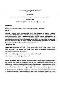
Figure 1: This sequence illustrates the adaptive repulsion and fissioning mechanism. The topmost image shows a deliberately poor sampling of a blobby cylinder produced using simple repulsion: the cylinder was rapidly stretched, leaving the sample points behind. The remaining images, from top to bottom, show the recovery of good sampling when adaptive repulsion is enabled. The particles at the frontier increase their radii of repulsion, rapidly filling the voids. As the particles slow down, they fission, restoring the desired sampling density. This process takes about four seconds on an SGI Crimson.
c °1994 ACM
Fb (x) = 1 x − ci i g (x) (s i )2 |x − ci |2 i g (x) Fs i (x) = −2 (s i )3
Fci (x) = −2
If we assume that g i (x) = 0 beyond a radius of 3s i , then a conservative bounding box for blobby spheres is the bounding box of non-blobby spheres with centers ci and radii 3s i . We have also implemented spheres and blobby cylinders. A blobby cylinder function is defined to be the sum of Gaussians of the distance to each of several line segments. A system of k blobby cylinders has 7k + 1 parameters: a bias plus seven parameters for each cylinder (two endpoints and a standard deviation). It is often useful to freeze some of these parameters to a fixed value so that they will not be modified during interaction. This is
6
Computer Graphics, Proc. SIGGRPAH ’94.
of the linear system, which has cost O(n 3 ), the computation of repulsion forces between all pairs of floaters, which currently has cost O(r 2 ), and the display of the floaters, which has cost O(r ) (with a large constant). Our current system does not handle overconstrained surfaces, so m ≥ n, thus the total asymptotic cost of the algorithm is O(mn 2 + r 2 ) per iteration. We have run simulations as complex as m = 56, n = 10, r = 500. Above r = 250 floaters, the O(r 2 ) repulsion cost has dominated, but this could easily be optimized using spatial data structures. For smaller numbers of floaters (r < 150), our system runs at interactive rates (10 Hz or faster on a Silicon Graphics workstation with 100 MHz processor). The following parameter settings are recommended (where d is surface diameter):
done simply by leaving them out of the q and Fq vectors. To get blobs of equal radii, for instance, one would omit all s i . The system starts up with a single floater positioned arbitrarily in the bounding box of the surface and then begins the physical simulation by repeating the following differential step: • The user interface sets desired control point velocities P i . Stationary control points of course have zero desired velocity, while control points being dragged by the user have desired velocities that are calculated as a function of cursor position. • Set Q, the desired values for the time derivatives of the surface parameters. These are typically set to zero to minimize parametric change in the surface, but they could also be calculated to attract the surface toward a default shape. ˙ as con• Compute the actual surface parameter changes, q, strained by the control point velocities, using equations 7 and 8. • Compute repulsion forces between floaters to set their desired velocities P i , using equation 9. • Compute actual floater velocities, as constrained by the already-computed surface time derivatives, using equation 5. (When the gradient Fx is near zero, however, the surface is locally ill-defined, and it is best to leave such floaters motionless, i.e., p˙ i = 0.) • Compute the change to floater repulsion radii, σ˙ i , using equations 12, 10, and 13. • Update the positions of the control points and floaters using Euler’s method, that is: pi (t + 1t) = pi (t) + 1t p˙ i (t), and ˙ similar formulas to update the surface parameters q from q, and the floater repulsion radii σ i from σ˙ i . • Test each floater for possible fission/death. • Redisplay the floaters and control points as disks tangent to the surface, with normal given by Fx and (for floaters) radius proportional to σ i . Using the mouse, the user can pick a control point and move it in a plane perpendicular to the view direction. Pulling control point i sets the desired control point velocity P i . Since the velocities feed into the constrained optimization solution, which in turn feeds into a numerical differential equation solver, some care must be taken to ensure that control point motions are reasonably smooth and well behaved, which they might not be if positions were set directly by polling the pointing device. A simple solution which works well is to make the velocity of the dragged particle proportional to the vector from the point to the 3-D cursor position. This in effect provides spring coupling between the cursor and the control point. Although the control point can lag behind the cursor as a result, performance is brisk enough that the lag is barely noticeable. Similar dragging schemes are described in [14,31]. The user can also create and delete control points and adjust the desired repulsion radius σˆ through a slider. The matrix in equation 7 is symmetric and in general positive definite. It thus lends itself to solution by Cholesky decomposition [23], which is easy to implement, robust and efficient. However, the matrix can become singular if inconsistent or redundant constraints are applied, that is if the number of constraints exceeds m, or if some of the Fqi ’s are linear combinations of others. While the former condition is easy to detect by counting, the latter is not. The problem of singularities can be circumvented by using a leastsquares technique, or singular value decomposition [23]. The system is fast enough to run at interactive rates. Let m be the number of degrees of freedom of the implicit surface, let n be the number of control points, and let r be the number of floaters. The most expensive parts of the algorithm are the computation of the n × n matrix of equation 7, which has cost O(mn 2 ), the solution
c °1994 ACM
PARAMETER 1t = .03 φ = ρ = 15
α=6 Eˆ = .8α β = 10 σˆ = d/4 or less σ max = max( d2 , 1.5σˆ ) γ =4 ν = .2 δ = .7
MEANING time step feedback coefficients to keep particles from drifting off surface, and keep particles energized, respectively repulsion amplitude desired energy to prevent divide-by-zero desired repulsion radius (usercontrollable) maximum repulsion radius (note that this changes over time) equilibrium speed (multiple of σi) ˆ for fissioning fraction of E, fraction of σˆ , for death
Most of these parameters can be set once and forgotten. The only parameter that a user would typically need to control is the desired repulsion radius, σˆ . Overall, the method meets our goals, it is fast, and it has proven to be very robust. It has recovered from even violent user interaction causing very rapid shape change. The adaptive sampling, fission, and death techniques seem to be well tuned and to work well together, as we have not seen the system oscillate, diverge, or die with the current parameter settings. During interaction, σˆ is the only parameter that needs to be varied. Another result of this work is that we have discovered that implicit surfaces are slippery: when you attempt to move them using control points they often slip out of your grasp.
6
Conclusions
In this paper we have presented a new particle-based method for sampling and control of implicit surfaces. It is capable of supporting real-time rendering and direct manipulation of surfaces. Our control method is not limited to algebraic surfaces as many previous techniques are; it allows fast control of general procedural implicit functions through control points on the surface. We have presented a dynamic sampling and rendering method for implicit surfaces that samples a changing surface more quickly than existing methods. The use of constraint methods allows particles to follow the surface as it changes, and to do this more rapidly and accurately than with penalty methods. Our algorithms for adaptive repulsion, fission, and death of particles are capable of generating good sampling patterns much more quickly than earlier repulsion schemes, and they sample the surface well even during rapid shape changes.
7
Computer Graphics, Proc. SIGGRPAH ’94.
There are a number of directions for future research. We intend to investigate other uses for the samplings we obtain. One of these is the calculation of surface integrals for area, volume, or surface fairness measures such as those described in [19,30]. Another is the creation of polygon meshes. To polygonize a surface within the framework presented here it is necessary to infer topology from the sample points. This is more difficult than finding a polygonization from a set of samples on a grid in 3-D, as in marching cubes algorithms, where an approximate topology is suggested by the signs of the samples and by the topology of the grid itself. Delaunay triangulation in 2-D or 3-D is one possible way to extract topology [12,27]. A more robust alternative would employ Lipschitz conditions and interval arithmetic [26]. To preserve the basic advantages of our method, we would require a polygonization algorithm that allows efficient dynamic updates as the surface changes. Although we developed it to sample implicit surfaces, our adaptive repulsion scheme can be applied to meshing or sampling of parametric surfaces as well: each floater would be defined by its position in the surface’s 2-D parameter space, rather than position in 3-D space. Several performance and numerical issues remain to be addressed. As we tackle more complex models, we could exploit sparsity in F’s dependence on q. Notably, with local bases such as blobby models, the dependence of F on faraway elements is negligible. An additional numerical issue is the handling of singular constraint matrices, due to overdetermined or dependent constraints. Excellent results can be obtained using least-squares techniques. An additional area of investigation is the use of local criteria, notably surface curvature, to control sampling density. Surface curvature can be measured directly, at the cost of taking additional derivatives of F. Since this places a considerable extra burden on the implementor of implicit primitives, an alternative is to estimate curvature at each floater based on positions and normals of nearby points. Having established a desired density at each point, based on curvature or any other criterion, relatively simple modifications to the adaptive repulsion scheme will yield the desired nonuniform density. Another possible density criterion is the user’s focus of interest, e.g. the neighborhood of a control point being dragged. Finally, there is room for considerable further work in interactive sculpting of implicit surfaces. Dragging one control point at a time can be somewhat limiting given the slippery behavior of the surface. However, the basic control-point machinery developed here could be used to build more complex sculpting tools that influence multiple surface points in coordinated ways.
Acknowledgements The authors wish to thank Scott Draves and Sebastian Grassia for their contributions to this work. This research was supported in part by a Science and Technology Center Grant from the National Science Foundation, #BIR-8920118, by an NSF High Performance Computing and Communications Grant, #BIR-9217091, by the Engineering Design Research Center, an NSF Engineering Research Center at Carnegie Mellon University, by Apple Computer, Inc, and by an equipment grant from Silicon Graphics, Inc. The second author was supported by NSF Young Investigator Award #CCR-9357763. Figure 2: This sequence illustrates the construction of a shape composed of blobby cylinders. The shape was created by direct manipulation of control points using the mouse. In the topmost image, all three cylinder primitives are superimposed. Each subsequent image represents the result of a single mouse motion.
c °1994 ACM
References [1] Chandrajit Bajaj, Insung Ihm, and Joe Warren. Higher-order interpolation and least-squares approximation using implicit
8
Computer Graphics, Proc. SIGGRPAH ’94.
[19] Henry Moreton and Carlo S´equin. Functional minimization for fair surface design. Computer Graphics, 26(2):167–176, 1992. Proc. Siggraph ’92.
algebraic surfaces. ACM Trans. on Graphics, 12(4):327–347, Oct. 1993. [2] David Baraff. Analytical methods for dynamic simulation of non-penetrating rigid bodies. Computer Graphics, 23(3):223– 232, July 1989.
[20] Shigeru Muraki. Volumetric shape description of range data using “blobby model”. Computer Graphics (SIGGRAPH ’91 Proceedings), 25(4):227–235, July 1991.
[3] David Baraff. Curved surfaces and coherence for nonpenetrating rigid body simulation. Computer Graphics, 24(4):19–28, August 1990.
[21] Paul Ning and Jules Bloomenthal. An evaluation of implicit surface tilers. Computer Graphics and Applications, pages 33–41, Nov. 1993.
[4] David Baraff and Andrew Witkin. Dynamic simulation of nonpenetrating flexible bodies. Computer Graphics, 26(2):303– 308, 1992. Proc. Siggraph ’92.
[22] Vaughan Pratt. Direct least-squares fitting of algebraic surfaces. Computer Graphics (SIGGRAPH ’87 Proceedings), 21(4):145–152, July 1987.
[5] Ronen Barzel and Alan H. Barr. A modeling system based on dynamic constaints. Computer Graphics, 22:179–188, 1988.
[23] W.H. Press, B.P. Flannery, S. A. Teukolsky, and W. T. Vetterling. Numerical Recipes in C. Cambridge University Press, Cambridge, England, 1988.
[6] J. Baumgarte. Stabilization of constraints and integrals of motion in dynamical systems. Computer Methods in Applied Mechanics, 1972.
[24] A. Ricci. A constructive geometry for computer graphics. Computer Journal, 16(2):157–160, May 1973.
[7] Thaddeus Beier. Practical uses for implicit surfaces in animation. In Modeling, Visualizing, and Animating Implicit Surfaces (SIGGRAPH ’93 Course Notes), pages 20.1–20.10. 1993.
[25] T. Sederberg. Piecewise algebraic surface patches. Computer Aided Geometric Design, 2(1-3):53–60, 1985. [26] John M. Snyder. Generative Modeling for Computer Graphics and CAD. Academic Press, Boston, 1992.
[8] James F. Blinn. A generalization of algebraic surface drawing. ACM Trans. on Graphics, 1(3):235–256, July 1982. [9] Jules Bloomenthal. Polygonization of implicit surfaces. Computer Aided Geometric Design, 5:341–355, 1988.
[27] Richard Szeliski and David Tonnesen. Surface modeling with oriented particle systems. Computer Graphics (SIGGRAPH ’92 Proceedings), 26(2):185–194, July 1992.
[10] Jules Bloomenthal. An implicit surface polygonizer. In Paul Heckbert, editor, Graphics Gems IV, pages 324–350. Academic Press, Boston, 1994.
[28] Greg Turk. Generating textures on arbitrary surfaces using reaction-diffusion. Computer Graphics (SIGGRAPH ’91 Proceedings), 25(4):289–298, July 1991.
[11] Jules Bloomenthal and Brian Wyvill. Interactive techniques for implicit modeling. Computer Graphics (1990 Symp. on Interactive 3D Graphics), 24(2):109–116, 1990.
[29] Greg Turk. Re-tiling polygonal surfaces. Computer Graphics (SIGGRAPH ’92 Proceedings), 26(2):55–64, July 1992. [30] William Welch and Andrew Witkin. Variational surface modeling. Computer Graphics, 26(2):157–166, 1992. Proc. Siggraph ’92.
[12] Luiz Henrique de Figueiredo, Jonas de Miranda Gomes, Demetri Terzopoulos, and Luiz Velho. Physically-based methods for polygonization of implicit surfaces. In Graphics Interface ’92, pages 250–257, May 1992.
[31] Andrew Witkin, Michael Gleicher, and William Welch. Interactive dynamics. Computer Graphics, 24(2):11–21, March 1990. Proc. 1990 Symposium on 3-D Interactive Graphics.
[13] Phillip Gill, Walter Murray, and Margret Wright. Practical Optimization. Academic Press, New York, NY, 1981.
[32] Andrew Witkin and William Welch. Fast animation and control of non-rigid structures. Computer Graphics, 24(4):243–252, July 1990. Proc. Siggraph ’90.
[14] Michael Gleicher and Andrew Witkin. Through-the-lens camera control. Computer Graphics, 26(2):331–340, 1992. Proc. Siggraph ’92.
[33] Brian Wyvill, Craig McPheeters, and Geoff Wyvill. Data structure for soft objects. The Visual Computer, 2(4):227–234, 1986.
[15] Herbert Goldstein. Classical Mechanics. Addision Wesley, Reading, MA, 1950. [16] Huges Hoppe, Tony DeRose, Tom Duchamp, John McDonald, and Werner Stuetzle. Mesh optimization. In SIGGRAPH 93 Proceedings, pages 19–26, July 1993. [17] David J. Jevans, Brian Wyvill, and Geoff Wyvill. Speeding up 3-D animation for simulation. In Proc. MAPCON IV (Multi and Array Processors), pages 94–100, Jan. 1988. [18] William E. Lorensen and Harvey E. Cline. Marching cubes: A high resolution 3D surface reconstruction algorithm. Computer Graphics (SIGGRAPH ’87 Proceedings), 21(4):163– 170, July 1987.
c °1994 ACM
9
Computer Graphics, Proc. SIGGRPAH ’94.