Oct 5, 2009 - in the case of an animated implicit surface, the polygonal ..... ple, the NVidia series 8 and above or any other OpenGL 3 ... int mask = 0;.
Technical Report TR-NCCA-2009-04
FAST RELIABLE RAY-TRACING OF PROCEDURALLY DEFINED IMPLICIT SURFACES USING REVISED AFFINE ARITHMETIC Oleg Fryazinov, Alexander Pasko and Peter Comninos
The National Centre for Computer Animation Bournemouth Media School Bournemouth University Talbot Campus, Poole, Dorset BH12 5BB United Kingdom 2009
Technical Report TR-NCCA-2009-04 ISBN 1-85899-123-4 Title Fast Reliable Ray-tracing of Procedurally Defined Implicit Surfaces Using Revised Affine Arithmetic Author(s) Oleg Fryazinov, Alexander Pasko and Peter Comninos Keywords Ray Tracing, Implicit Surfaces, Function Representation, Revised Affine Arithmetic Abstract Fast and reliable rendering of implicit surfaces is an important area in the field of implicit modelling. Direct rendering, namely raytracing, is shown to be a suitable technique for obtaining goodquality visualisations of implicit surfaces. We present a technique for reliable ray-tracing of arbitrary procedurally defined implicit surfaces by using a modification of Affine Arithmetic called Revised Affine Arithmetic. A wide range of procedurally defined implicit objects can be rendered using this technique including polynomial surfaces, constructive solids, pseudo-random objects, procedurally defined microstructures, and others. We compare our technique with other reliable techniques based on Interval and Affine Arithmetic to show that our technique provides the fastest, while still reliable, ray-surface intersections and ray-tracing. We also suggest possible modifications for the GPU implementation of this technique for real-time rendering of relatively simple implicit models and for near real-time for complex implicit models. Report date 5 October 2009 Web site to download from http://eprints.bournemouth.ac.uk/ The authors’ e-mail addresses {ofryazinov,apasko,peterc}@bournemouth.ac.uk Supplementary notes
The National Centre for Computer Animation Bournemouth Media School Bournemouth University Talbot Campus, Poole, Dorset BH12 5BB United Kingdom
1
1. Introduction In recent years, implicit surfaces (isosurfaces of trivariate real functions) have proved to be a powerful and simple solution to some complex problems in the area of modelling and animation. For example, implicit surfaces provide solutions for surface reconstruction from scattered points and for fluid simulation. Several operations, such as sweeping, metamorphosis and offsetting can be implemented quite easily with implicit models unlike traditional boundary-representation models. However, modelling with the whole range of implicit surfaces is still a complicated task because interactive rendering of arbitrary implicit surfaces is still an open problem. Because of that, most of implicit modelling tools to date are limited to a narrow range of implicit surfaces or do not have an interactive mode. Currently, there are two ways to render an implicit model: generation of a polygonal mesh and direct rendering using ray-tracing. Polygonization is a well-known and widely used technique for rendering of implicit surfaces. However, in many cases, when the model has sharp or thin features, large numbers of small-sized disjoint elements or internal microstructures, the generation of an appropriate polygonal mesh takes a long time and requires a large amount of memory. In many cases additional techniques to refine the polygonal mesh are needed. Moreover, in the case of an animated implicit surface, the polygonal mesh has to be created for each frame and it is thus inappropriate for interactive applications. A more promising technique is that of interactive direct rendering of implicit surfaces using ray-casting and ray-tracing. Traditionally the main disadvantage of direct rendering of implicit surfaces was their slow speed due to the large number of ray-surface intersection calculations. With recent developments of hardware this problem becomes less critical, but not insignificant all together. Many techniques of ray-casting and ray-tracing implicit surfaces have been developed. However, the majority of these techniques have disadvantages, because they either work with a small range of implicit surfaces (for instance those defined only by polynomials), or not reliable. For example, classic approximate techniques, such as ray marching, are fast, but can easily miss sharp features and small components. Classical numerical techniques, such as the Newton search require different signs of the defining function at the ends of the ray interval, which is inappropriate for arbitrary rays. Sphere-tracing based techniques require a distance property of the defining function, which can not be provided for general models. Techniques based on interval analysis and other reliable numerical computations have also been applied to the ray-tracing of implicit surfaces. However, classic Interval Arithmetic is slow because of the interval overestimation. The problem considered in this paper is that of finding a technique for ray-tracing of general implicit surfaces, that has the following properties:
• Its ray-surface intersection procedure should be reliable, i.e. no roots should be missed. • A wide range of implicit models should be supported – meaning that the algorithm should be able to work with procedurally defined models as well as with algebraic ones. • The procedure should be fast and suitable for a GPU implementation of interactive rendering. In this paper we propose to use Revised Affine Arithmetic as a fast and reliable technique for calculating the range of a function for a given interval and hence the core for the ray-surface intersection procedure. The main contributions in this paper are: 1) a new algorithm for reliable ray-tracing of general procedurally defined implicit surfaces using Revised Affine Arithmetic in contrast to the formerly reported applications of Reduced Affine Arithmetic exclusively to algebraic surfaces defined by polynomials; 2) a technique for optimising the proposed ray-tracing procedure by using argument pruning and cell culling; 3) a possible implementation of this algorithm on both the CPU and GPU. 2. Related work Ray-tracing of implicit surfaces is a well-researched area. The classic techniques for ray-tracing of implicit surfaces were presented in [Har93]. Most of the described techniques are approximate and can miss small surface features, but on the other hand they are suitable for all types of implicit surfaces. Later, several techniques were presented for particular types of implicit surfaces that provide not only speed but also reliability. Thus, in [Har94] a distance property is needed for the ray-tracing procedure, in [She99] blobs, metaballs and convolution surfaces are the type of implicit surface that can be rendered fast. Another way to increase speed of ray-tracing is by reducing the number of processed rays intersecting the implicit surface. In [Has03], image-space subdivision is used, while [GM07a] uses progressive refinement. Using specialised hardware also increases the speed of ray-tracing. Many papers use the GPU for real-time rendering, however most of these papers have focused on polygonal meshes [PBMH02], parametric surfaces [LB06] and volumetric data [KW03]. GPU-based ray-tracing of implicit surfaces was introduced only for particular types of the objects, such as radial-basis functions [CD05], lowdegree implicit surfaces [KOKK06] and discrete isosurfaces [HSS∗ 05]. Ray-tracing of general implicit surfaces on the GPU was performed in [FP08] [SNar] by using approximate methods. Reliable computational techniques based of Interval Arithmetic have been known for a long time. However, most of the literature relates to fields such as global optimisation rather than computer graphics. The works of [Mit91] and [Sny92] discussed applications of Interval Arithmetic
2
for computer graphics purposes, and Affine Arithmetic was used for ray-tracing of implicit surfaces in [dCFG99] . A good comparison of different interval techniques can be found in [MSVW01], however the list of the implicit models used in this paper is limited to those given in the polynomial form. Interval Arithmetic and Reduced Affine Arithmetic are applied for fast rendering of implicit surfaces by using the GPU in [KHK∗ 09]. A more detailed comparison of these techniques with the one proposed here can be found in the "Results" section below. In this paper, we use Revised Affine Arithmetic [VSHFar], which was introduced recently for the purposes of constraint propagation and has not yet been used in computer graphics.
3. Background
where xn are known real coefficients and εn are noise symbols, i.e. symbolic variables whose values are assumed to lie in the interval εn ∈ [−1, 1]. In Affine Arithmetic, formula evaluation is performed by replacing operations on real quantities by their affine forms. Similar to Interval Arithmetic, the inclusion property is applied in Affine Arithmetic, i.e. for any operation ⊗, A ⊗ B ⊂ {a ⊗ b, a ∈ A, b ∈ B}, where a and b are real values and A and B are uncertain values in affine form. All operations on affine forms can be divided into affine (exact) and non-affine (approximate) operations. An affine operation is a function that can be represented by the linear combination of the noise symbols of its arguments. For example, a multiplication by a constant is an affine operation:
3.1. Procedurally defined implicit surfaces A zero level set or an isosurface of a trivariate real function f of a point with coordinates (x, y, z) is traditionally called an implicit surface and is defined as f (x, y, z) = 0. It can also be considered as the boundary of a solid (three-dimensional manifold) defined by the inequality f (x, y, z) ≥ 0. There are many different ways to specify the function f (x, y, z). The simplest form is that of an algebraic implicit surface defined by a polynomial function. Most of the extant work on reliable ray-tracing concentrates solely on algebraic surfaces. More complex forms involve exponential, square root, trigonometric and other non-linear functions. We deal with the most general form of procedurally defined implicit surfaces, where the function f is evaluated by some procedure involving all kinds of non-linear functions as well as loops and conditional operations. This allows us to cover skeletonbased implicit surfaces [BW97], Constructive Solid Geometry (CSG) objects defined by nested R-functions [Sha07], solid noise [PH89] [Gar84], fractals and other complex objects.
3.2. Affine Arithmetic Affine Arithmetic is a technique for performing computations on uncertain numerical values. The main idea of Affine Arithmetic is the calculation of an uncertain value (function) based on other uncertain values (arguments). Initially this model was introduced for self-validated numerical computations as an alternative to Interval Analysis – in some literature Affine Arithmetic is still considered as the modification of general Interval Arithmetic – and currently it is used in many different areas of computer science [dS97]. By keeping track of the errors for each computed quantity, Affine Arithmetic provides much tighter bounds for computed quantities compared to classical Interval Arithmetic. Uncertain values in Affine Arithmetic are represented by affine forms, i.e. polynomials of the form: xˆ = x0 + x1 ε1 + x2 ε2 + ... + xn εn
αxˆ = αx0 + αx1 ε1 + αx2 ε2 + ... + αxnεn Non-affine operations can not be performed over the linear combination of the noise symbols. In this case an approximate affine function is used and a new noise symbol is added to the affine form to represent the difference between the non-affine function and its approximation. For example, the multiplication of two affine forms is a non-affine operation and introduces a new noise symbol, εn+1 : xˆ ∗ yˆ = x0 y0 + (x0 y1 + x1 y0 )ε1 + ... + (x0 yn + xn y0 )εn +
n
n
i=1
i=1
( ∑ |xi | ∑ |yi |)εn+1
In the general case any operation can be represented in an affine form: xˆ ⊗ yˆ = αxˆ + βyˆ + ζ ± δ where the value of the new noise symbol is represented by δ. In [dS97], different approximation techniques are discussed for the affine form of several functions. 3.3. Reduced Affine Arithmetic Pure Affine Arithmetic is computationally- and memory expensive and can not be used in algorithms where the reduction of computational complexity is equally important as the quality of the computational result. In [Mes02], several reduced affine forms were introduced to reduce the number of computations in Affine Arithmetic by accumulating errors. The Affine Form 1 (AF1) is the simplest one and represents the uncertain quantity as: n
xˆ = x0 + ∑ xi εi + xn+1 εn+1 i=1
The noise symbols ε1 , ..., εi represent the errors of the initial arguments. The last noise symbol represents all the errors after the non-affine operations. Reduced Affine Arithmetic [GM07b] was introduced for the AF1 and it was shown that the best results from the computational point
3
of view can be obtained by using only two noise symbols, i.e n=1. Thus, in Reduced Affine Arithmetic the first noise symbol represents the error on the argument interval and the second noise symbol represents the accumulation noise symbol after all the non-affine operations have taken place. Despite the fact that the general affine operation was not clearly discussed in that paper, it can be defined similarly to the ordinary affine operation with condensation as follows: n
xˆ ⊗ yˆ = (αx0 + βy0 + ζ) + ∑ (αxi + βyi ) + (|δ + αxn+1 + i=1
βyn+1 |)εn+1 The length of the reduced affine form remains the same after the affine computations, however the accumulation of all the errors in one symbol leads to a wider error and thus to a widening of the bounds of the computed value. 3.4. Revised Affine Arithmetic Revised Affine Arithmetic was introduced by Vu et al. [VSHFar] for the purposes of numerical constraint propagation and reduces the problem of growth of the error in the last (accumulating) noise symbol. The revised affine form is similar to the reduced affine form: n
xˆ = x0 + ∑ xi εi + ex [−1, 1], ex ≥ 0 i=1
Despite their similar forms and the fact that they have the same geometric sense, the reduced and revised affine forms have different mathematical backgrounds. While in Reduced Affine Arithmetic we accumulate errors after non-affine operations in the last noise symbol, in Revised Affine Arithmetic we accumulate the error in the symmetrical interval. From the formal point of view, the difference between the Reduced Affine Arithmetic and the Revised Affine Arithmetic is in the definition of the general non-affine operation and the tight form for multiplication. The binary affine operation is defined as: n
f (x, ˆ y) ˆ = (αx0 + βy0 + ζ) + ∑ (αxi + βyi ) + (δ + |α|ex + i=1
|β|ey )[−1, 1] where α, β and ζ can be taken from the affine approximation of the function f . The unary affine operation is defined in the same way: n
f (x) ˆ = (αx0 + ζ) + ∑ αxi + (δ + |α|ex )[−1, 1] i=1
The formula for the multiplication is defined as: n
n
i=1
i=1
n
n
i=1
i=1
where u = ∑ |xi |, v = ∑ |yi |. As for standard Affine Arithmetic, Revised Affine Arithmetic has an inclusion property. In our technique we use a shortest possible revised affine form, i.e. i = 1. 4. Ray-tracing with Revised AA The main part of any ray-tracing procedure for implicit surfaces is the calculation of the zero roots of the defining function in the ray-surface intersection procedure. In this section we show how Revised Affine Arithmetic can be used for the intersection point calculation and we present several techniques for speeding up this calculation. 4.1. Ray-surface intersection Our algorithm is based on a ray-surface intersection technique for implicit surfaces that uses interval techniques, which originally appeared in [Mit91]. We present the raysurface intersection procedure in Algorithm 1. Algorithm 1 Ray-surface intersection Procedure: bool intersect(tmin , tmax ) Calculate the affine form F for the function on the interval [tmin ,tmax ] Get the range of the function from the affine form if the range of the function does not include a 0 value then return FALSE (no roots in this interval); end if Calculate the argument estimation from the affine form: t 0 min ,t 0 max Find the pruned argument range: tmin = max(tmin ,t 0 min ); tmax = min(tmax ,t 0 max ); if the length of the argument interval is less than some predefined accuracy then Store the midpoint of the interval as the root; return TRUE; end if Calculate the midpoint of the argument range: tmid = (tmin + tmax )/2; Repeat the procedure for the two subintervals: bool b1 = intersect(tmin ,tmid ); if b1 is TRUE and only the first root is needed then return TRUE; end if bool b2 = intersect(tmid ,tmax ); if b2 is TRUE then return TRUE; end if return FALSE;
xˆ ∗ yˆ = (x0 y0 + 12 ∑ xi yi ) + ∑ (x0 yi + xi y0 )εi + exy [−1, 1] n
exy = ex ey + ey (|x0 | + u) + ex (|y0 | + v) + uv − 12 ∑ |xi yi | i=1
The basic idea of the algorithm is quite simple: we calculate the range of the function for the given argument interval
4
(a)
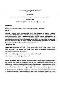
Figure 2: Pruning of the interval [tmin ,tmax ] to the interval [t 0 min ,t 0 max ] after the evaluation of the revised affine form for the function.
these variables: xˆ = x0 + tˆ ∗ dx , yˆ = y0 + tˆ ∗ dy , zˆ = z0 + tˆ ∗ dz (b)
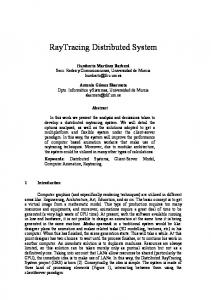
Figure 1: a) The revised affine form for the function on the interval [tmin ,tmax ] b) The revised affine form for the function on the two subintervals after the dichotomy.
using Revised Affine Arithmetic, we reject the interval if the range does not include the zero value, otherwise we subdivide the interval into two intervals by using dichotomy and we repeat the procedure for both subintervals. An example of the affine form for the function before and after the dichotomy is shown in the figure 1. Note that in the case when only the first root is needed (for example, for primary rays), we can exit from the procedure earlier if we have found a root in the first subinterval after the recursive procedure. Below we explain several details of the algorithm. 4.1.1. Interval range for the function in Revised Affine Arithmetic The calculation of the interval of the function over the interval of the arguments is performed in three steps. First, we obtain the revised affine form for the argument interval: tmin + tmax tmax − tmin + ε1 2 2 We also obtain the affine forms for the coordinate variables x, y and z, as the defining function is usually defined over tˆ =
Here x0 , y0 , z0 are the coordinates for the ray origin and dx , dy , dz are the coordinates for the ray direction. For each ray these coordinates are constant. Secondly, we calculate the range for the function by evaluating its revised affine form. The revised affine form is obtained from the procedural definition of the function by replacing all the operations on real numbers by operations on the revised affine forms. Finally, we obtain the range of the function from the affine form fˆ = f0 + f1 ε1 ± e f : fmin = f0 − | f1 | − e f fmax = f0 + | f1 | + e f 4.1.2. Argument pruning One of the useful properties of the reduced and hence the revised affine forms is that of argument pruning (a term taken from literature of interval slope methods), that means that we can not only calculate the function range for the interval, but also can narrow the argument range in case the root exists in this interval. In [GM07b], the argument pruning formulation (the term interval optimisation is used in the paper) was suggested for Reduced Affine Arithmetic. As the geometric meaning of the revised affine form is similar to that of the reduced affine form, an analogous formulation can be used as follows. Given the revised affine form for the function fˆ = f0 + f1 ε1 ± e f for the interval tˆ = t0 + t1 ε1 , providing
5
that t1 6= 0, we have:
tˆ − t0 ε1 = t1
f t tˆ − t0 ± e f = ( f0 − f1 0 ) + tˆ 1 ± e f fˆ = f0 + f1 t1 t1 t1 The geometric meaning of this form in 2D space {t, f} is the parallelogram bounded by the lines f = ( f0 − tt01 ) + tˆ tf11 − e f , f = ( f0 − tt10 ) + tˆ tf11 + e f and the coordinate lines t = tmin and t = tmax . This parallelogram intersects the axis t at two points provided that f1 6= 0 and e f 6= 0: t 0 = t0 −
t1 f 0 t ±ef 1 f1 f1
If these two points lie inside the interval [tmin ,tmax ], the interval can be pruned. (see Fig. 2). 4.2. Cell Culling If we subdivide the scene to be rendered into rectangular cells, the ray-tracing procedure can be accelerated by rejecting the cells where zero roots of the function do not exist. This can be done because of the interval nature of Revised Affine Arithmetic. Given a cell intersected by a bundle of initial rays on the 3D interval [(xmin , ymin , zmin ), (xmax , ymax , zmax )] the cell can be entirely rejected if the function range for the affine form on the cell interval does not include a zero value. The calculation of the function range is slightly different in this case as we have to convert into the revised affine form the three intervals for x, y, z independently: xˆ =
xmin + xmax xmax − xmin + ε1 2 2
yˆ =
ymin + ymax ymax − ymin + ε1 2 2
zmin + zmax zmax − zmin + ε1 2 2 If the function range includes a zero value, the cell can be subdivided in octree- or quadtree-like manner until we reach the pixel level and apply the ray-surface intersection. The algorithm for ray-tracing in this case is presented in Algorithm 2. zˆ =
The same technique can also be used for secondary rays (for example, for a shadow test). In this case we take a bundle of rays from the local area of the implicit surface, calculate the argument range for this bundle of rays and then perform the intersection test with another implicit object. 5. Implementation In this section we present details of the implementation of ray-tracing of procedurally defined implicit surfaces on the CPU and the GPU. The implementation can be divided into
Algorithm 2 Ray-tracing of implicit surfaces with cell culling We start with a bundle of rays from pixels on the interval [(xsmin , ysmin ), (xsmax , ysmax )] in screen space if xsmax − xsmin ≤ 1 AND ysmax − ysmin ≤ 1 then We are at the pixel level, apply ray-tracing procedure for this particular ray end if Calculate the interval for the coordinates in object space Calculate the affine forms for x, y and z Calculate the affine form F for the function for these affine forms Get the range of the function from the affine form if the range of the function does not include a 0 value then return FALSE (object intersection with this bundle); end if Subdivide the interval [(xsmin , ysmin ), (xsmax , ysmax )] into four subintervals by using a quadtree Repeat the procedure recursively for these subintervals
three parts: the Revised Affine Arithmetic representation, the function representation in the revised affine form and the ray-tracing procedure. 5.1. Affine form representation As we stated above, the revised affine form is a polynomial with three terms. Thus, the affine form in the software implementation can be represented as a three-component vector, where the first component represents x0 , the second represents the noise symbol for the error along the ray and the third represents the half-length of the accumulating interval. The calculations in Affine Arithmetic can be performed on these vectors. Almost all of the arithmetic operations have to be overridden as only summation in the Revised Affine Arithmetic matches the standard vector summation. For example, the subtraction and multiplication can be implemented as follows: vec3 ra_subtraction(vec3 x, vec3 y){ vec3 ret; ret[0] = x[0] - y[0]; ret[1] = x[1] - y[1]; ret[2] = x[2] + y[2]; return ret; } vec3 ra_multiplication(vec3 x, vec3 y){ vec3 ret; ret[0] = x[0]*y[0]+0.5*x[1]*y[1]; ret[1] = x[0]*y[1]+y[0]*x[1]; ret[2] = x[2]*y[2]+ y[2]*(fabs(x[0])+fabs(x[1]))+ x[2]*(fabs(y[0])+fabs(y[1])) + 0.5*fabs(x[1]*y[1]); return ret; }
Similarly, non-affine operations can be implemented as operations on the three-component vectors. Note that for non-affine operations we are most likely to use the affine
6
constructor described above. For example, the square root operation needed for CSG models with R-functions can be implemented in this way by using Chebyshev approximation described in [dS97]: vec3 ra_sqrt(vec3 x){ vec2 i = ra_getinterval(x); if (i[1] < 0) return 0; if (i[0] < 0) i[0] = 0; double sq1 = sqrt(i[0]), sq2 = sqrt(i[1]); //calculate arguments for the revised affine form double alpha = 1/(sq1+sq2); double dzeta = (sq1+sq2)/8.0+0.5*sq1*sq2/(sq1+sq2); double delta = (sq2-sq1)*(sq2-sq1)/(8.0*(sq1+sq2)); //create the revised affine form vec3 ret; ret[0] = alpha*x[0]+dzeta; ret[1] = alpha*x[1]; ret[2] = alpha*x[2]+delta; return ret; }
In fact, any non-affine operation derived for pure Affine Arithmetic with known al pha, dzeta and delta can be adapted for Revised Affine Arithmetic in the same way.
5.2. Representation of the function As we stated that our algorithm works with procedurally defined implicit objects, this means that an object can be defined by a real-valued function of real-valued arguments. In the same way this function can be rewritten by using the following rules: • Calculate the revised affine forms for x, y, z (see example in the section 4.2) • Each variable depending on the input arguments is replaced by a variable of the revised affine type, while each variable not depending on the input arguments and constants is left in the real form. • If in the implementation of the Revised Affine Arithmetic operations are overridden, the rest of the code for the initial function is left unchanged, otherwise each operation has to be explicitly replaced by its revised affine version. The returned value of the rewritten function is the range of the function in the affine form, which is used in the raysurface intersection procedure described earlier. Similarly to other ray-tracing techniques for implicit surfaces, we use finite differences to obtain the normal vector for the shading and the secondary rays calculation. Therefore the real-valued defining function of real-valued arguments should be presented as well as the function in the revised affine form.
5.3. Modifications for the GPU implementation The speed of the calculation can be drastically improved by using hardware acceleration on the GPU. In this section we present possible modifications for the implementation of our algorithm to be accelerated this way.
5.3.1. Ray-surface intersection for the GPU Both the data structure and the ray-surface intersection procedure can easily be transferred to the GPU. The raytracing process is performed in the well-known GPGPU manner: the function definition, the Revised Affine Arithmetic code and the intersection code are in the fragment (pixel) shader which applies to the screen-sized polygon. The GPU-oriented ray-surface intersection procedure without a stack and recursion was proposed in [KHK∗ 09]. However, this implementation does not support argument pruning. In the following procedure we propose the modification of this implementation that supports argument pruning. Note that the usage of arrays requires a modern GPU (for example, the NVidia series 8 and above or any other OpenGL 3 compatible card): bool find_point(in vec3 vecStart, in vec3 vecDir, out vec3 vecIntersect) { int mask = 0; vec2 vInterval = vec2(0.0,1.0); vec3 func = aa_func(vecStart, vecDir, vInterval); vec2 interval_func = aa2ia(func); if (interval_func.x > 0.0 || interval_func.y < 0) return false; int d = 0; int dlast = int(log2(length(vecDir)/eps)); if (dlast > 32) dlast = 32; vec2 stack[32]; // stack[0] = vec2(0.0,0.5); for (;;) { vInterval = stack[d]; if (vInterval.y-vInterval.x < eps) { vecIntersect = vecStart+vInterval.x*vecDir; return true; } func = aa_func(vecStart, vecDir, vInterval); interval_func = aa2ia(func); if (interval_func.x = 0) { float t0 = (vInterval.x+vInterval.y)*0.5; float t1= (vInterval.y-vInterval.x)*0.5; float tmin1 = t0-model.x*t1/model.y-t1*abs(model.z/model.y); float tmax1 = t0-model.x*t1/model.y-t1*abs(model.z/model.y); if (tmin1 > vInterval.x) vInterval.x = tmin1; if (tmax1 < vInterval.y) vInterval.y = tmax1; if (d == dlast) { vecIntersect = vecStart+vInterval.x*vecDir; return true; } else { d++; mask *= 2; stack[d] = vec2(vInterval.x, (vInterval.x+vInterval.y)*0.5); continue; } } if (mod(mask, 2)) { for (int j = 0; j 50000
7 22 19 20 365 18 34 708 328 422
6 18 13 18 285 9 31 658 293 390
Table 1: Comparison of the ray-tracing procedures for different computational models. IA stands for Interval Arithmetic, AA for Affine Arithmetic, RAA* for Reduced Affine Arithmetic extended by non-affine operations and RevAA for Revised Affine Arithmetic. The timings for ray-tracing all the rays are shown in seconds.
Mitchell Bretzel Cup CSG
IA
RAA
28.1 83.8 0.56 4.3
90.1 90.2 5.12 14.6
RevAA (without culling) 92.2 90.2 5.95 15.6
RevAA (with culling) 97.4 90.5 6.1 17.2
Table 2: Comparison of ray-tracing procedures on the GPU. IA stands for Interval Arithmetic, AA for Affine Arithmetic, RAA for Reduced Affine Arithmetic and RevAA for Revised Affine Arithmetic. All models were rendered with using only primary rays at a resolution of 512*512 pixels. Timings are shown in FPS (frames per second) and all models were rendered using the same camera parameters.
research was done using Interval Arithmetic [Dia08], however further research using Affine Arithmetic and especially Revised Affine Arithmetic has to be done in this area. Also, during our tests we found that an affine form can be found not only for standard arithmetic and mathematical operators, but also for any set of operations. We suggest that the calculation of the function can be speeded up by replacing these parts of the code by some special affine functions. This is also an area that merits further research.
References [BW97] B LOOMENTHAL J., W YVILL B. (Eds.): Introduction to Implicit Surfaces. Morgan Kaufmann Publishers Inc., San Francisco, CA, USA, 1997. [CD05] C ORRIGAN A., D INH H. Q.: Computing and rendering implicit surfaces composed of radial basis functions on the GPU. In International Workshop on Volume Graphics (June 2005).
[dS97] DE F IGUEIREDO L. H., S TOLFI J.: Self-Validated Numerical Methods and Applications. Brazilian Mathematics Colloquium monographs. IMPA/CNPq, Rio de Janeiro, Brazil, 1997. [FP08] F RYAZINOV O., PASKO A.: Interactive ray shading of FRep objects. In WSCG’ 2008, Communications Papers proceedings (2008), pp. 145–152. [Gar84] G ARDNER G. Y.: Simulation of natural scenes using textured quadric surfaces. SIGGRAPH Comput. Graph. 18, 3 (1984), 11–20. [GM07a] G AMITO M. N., M ADDOCK S. C.: Progressive refinement rendering of implicit surfaces. Computers & Graphics 31, 5 (2007), 698–709. [GM07b] G AMITO M. N., M ADDOCK S. C.: Ray casting implicit fractal surfaces with reduced affine arithmetic. The Visual Computer 23, 3 (2007), 155–165. [Har93] H ART J. C.: Ray tracing implicit surfaces. In Siggraph 93 Course Notes: Design, Visualization and Animation of Implicit Surfaces (1993), pp. 1–16. [Har94] H ART J. C.: Sphere tracing: A geometric method for the antialiased ray tracing of implicit surfaces. The Visual Computer 12 (1994), 527–545.
[dCFG99] DE C USATIS J R . A., F IGUEIREDO L. H., G ATTASS M.: Interval methods for ray casting surfaces with affine arithmetic. In Proceedings of SIBGRAPI’99 - the 12th Brazilian Symposium on Computer Graphics and Image Processing (1999), pp. 65–71.
[Has03] H ASAN M.: An Efficient F-rep Visualization Framework. Master’s thesis, Faculty of Mathemetics, Physics and Informatics, Comenius University, Bratislava, Slovakia, Aug. 2003.
[Dia08] D IAZ J. F.: Improvements in the Ray Tracing of Implicit Surfaces based on Interval Arithmetic. PhD thesis, Departament d’Electronica, Informatica i Automatica, Universitat de Girona, Girona, Spain, Nov. 2008.
[HSS∗ 05] H ADWIGER M., S IGG C., S CHARSACH H., B UHLER K., G ROSS M.: Real-time ray-casting and advanced shading of discrete isosurfaces. Computer Graphics Forum 24 (September 2005), 303–312(10).
10 [KHK∗ 09] K NOLL A., H IJAZI Y., K ENSLER A., S CHOTT M., H ANSEN C. D., H AGEN H.: Fast ray tracing of arbitrary implicit surfaces with interval and affine arithmetic. Computer Graphics Forum 28, 1 (2009), 26–40.
Decocube f = 0.02 − ((x2 + y2 − 0.82)2 + (z2 − 1)2 ) ∗ ((y2 + z2 − 0.82)2 + (x2 − 1)2 ) ∗ ((x2 + z2 − 0.82)2 + (y2 − 1)2 )
[KOKK06] K ANAI T., O HTAKE Y., K AWATA H., K ASE K.: GPU-based rendering of sparse low-degree implicit surfaces. In GRAPHITE ’06: Proceedings of the 4th international conference on Computer graphics and interactive techniques in Australasia and Southeast Asia (2006), pp. 165–171.
CSG f = b|(s&((c1 \ c2 )|(c3 \ c4 )) \ c5 , where b = (0.36 − x2 )&(0.36 − y2 )&(0.36 − z2 ), s = 0.7056 − x2 − y2 − z2 , c1 = 0.09 − y2 − z2 , c2 = 0.04 − y2 − z2 , c3 = 0.09 − x2 − z2 , c4 = 0.04 − x2 − z2 , c5 = 0.25 − x2 − y2
[KW03] K RUGER J., W ESTERMANN R.: Acceleration techniques for GPU-based volume rendering. In VIS ’03: Proceedings of the 14th IEEE Visualization 2003 (VIS’03) (2003), pp. 287–292. [LB06] L OOP C., B LINN J.: Real-time GPU rendering of piecewise algebraic surfaces. ACM Transactions on Graphics 25, 3 (2006), 664–670. [Mes02] M ESSINE F.: Extensions of affine arithmetic: Application to unconstrained global optimization. Journal of Universal Computer Science 8, 11 (2002), 992–1015. [Mit91] M ITCHELL D. P.: Three applications of interval analysis in computer graphics. In Frontiers in Rendering course notes (1991), pp. 1–13. [MSVW01] M ARTIN R., S HOU H., V OICULESCU I., WANG G.: A comparison of Bernstein hull and affine arithmetic methods for algebraic curve drawing. In Proc. Uncertainty in Geometric Computations (July 2001), Kluwer Academic Publishers, pp. 143–154. [PBMH02] P URCELL T. J., B UCK I., M ARK W. R., H ANRAHAN P.: Ray tracing on programmable graphics hardware. ACM TOG 21, 3 (2002), 703–712. [PH89] P ERLIN K., H OFFERT E. M.: Hypertexture. SIGGRAPH Comput. Graph. 23, 3 (1989), 253–262. [PP04] PASKO G., PASKO A.: Trimming implicit surfaces. Vis. Comput. 20, 7 (2004), 437–447. [Sha07] S HAPIRO V.: Semi-analytic geometry with R-functions. Acta Numerica 16 (2007), 239–303. [She99] S HERSTYUK A.: Fast ray tracing of implicit surfaces. Computer Graphics Forum 18, 2 (1999), 139–147. [SNar] S INGH J. M., N ARAYANAN P. J.: Real-time ray-tracing of implicit surfaces on the GPU. IEEE Transactions on Visualization and Computer Graphics (2009, to appear). [Sny92] S NYDER J. M.: Interval analysis for computer graphics. In Computer Graphics (1992), pp. 121–130. [VPP∗ 04] V ILBRANDT C., PASKO G., PASKO A. A., FAYOLLE P.-A., V ILBRANDT T., G OODWIN J. R., G OODWIN J. M., K U NII T. L.: Cultural heritage preservation using constructive shape modeling. Computer Graphics Forum 23, 1 (2004), 25–42. [VSHFar] V U X.-H., S AM -H AROUD D., FALTINGS B.: Enhancing numerical constraint propagation using multiple inclusion representations. Annals of Mathematics and Artificial Intelligence (2009, to appear).
Appendix A: Formulas of surfaces used in the paper Mitchell f = 20 ∗ (x2 + y2 + z2 ) − 4 ∗ (x4 + (y2 + z2 )2 ) − 17x2 ∗ (y2 + z2 ) − 17 Bretzel f = 2 − 60 ∗ z2 − (x2 ∗ (1.21 − x2 )2 ∗ (3.8 − x2 )3 − 10 ∗ y2 )2
Sphere with noise f = 81 − x2 − y2 − z2 + (3.8 ∗ sin(1.5 ∗ x) + sin(1.111 ∗ x + 1.1 ∗ sin(1.5 ∗ x)) ∗ 1.624) ∗ (3.8 ∗ sin(1.5 ∗ y) + sin(1.111 ∗ x + 1.1 ∗ sin(1.5 ∗ x)) ∗ 1.299) ∗ (3.8 ∗ sin(1.5 ∗ y) + sin(1.111 ∗ x + 1.1 ∗ sin(1.5 ∗ x)) ∗ 2.598) Sphere with microstructure f = (((1 − x2 − y2 − z2 )&((sin(20 ∗ y) − 0.9)&(sin(20 ∗ z)−0.9))|((sin(20∗x)−0.9)&(sin(20∗z)−0.9))|((sin(20∗ x) − 0.9)&(sin(20 ∗ y) − 0.9)))|((1 − x2 − y2 − z2 ) \ (0.75 − x2 − y2 − z2 )))&(−z) CSG with blending f = (((c1 ∨b c2 )∧b s)∨b b)∧b (−c3 ), where b = (0.36 − x2 )&(0.36 − y2 )&(0.36 − z2 ), s = 0.7056 − x2 − y2 − z2 , c1 = 0.09 − y2 − z2 , c2 = 0.09 − x2 − z2 , c3 = 0.25 − x2 − 2 yq , ∨b denotes blending intersection: f1 ∨b f2 = f1 + f2 −
f12 + f22 + 1+ 0.5 2 2 , ∧b denotes blending union: f 1 ∧b f 2 = q f1 + f2 f1 + f2 + f12 + f22 + 1+ 0.5 f 2+ f 2 1
2
Hair f = o|(((1.8 ∗ sin(1.8 ∗ x ∗ √
9 ) + sx ) ∗ (1.8 ∗ sin(1.8 ∗ x2 +y2 +z2 9 y ∗ √ 2 2 2 ) + sy ) ∗ (1.8 ∗ sin(1.8 ∗ z ∗ √ 2 9 2 2 ) + sz ) − x +y +z x +y +z y2 x2 z2 x2 10)&(o+2)&y), where o = (1− 16 − 36 − 16 )|(1− 1.6129 − (z−3)2 (y+2.5)2 9 √2 2 2+ 2.25 − 1.6129 ), sx = 1.538 ∗ sin(1.33 ∗ x ∗ x +y +z 9 1.4 ∗ sin(1.8 ∗ x ∗ √ 2 2 2 )), sy = 1.538 ∗ sin(1.33 ∗ y ∗ x +y +z √ 2 9 2 2 + 1.4 ∗ sin(1.8 ∗ y ∗ √ 2 9 2 2 )), sz = 1.538 ∗ x +y +z x +y +z sin(1.33 ∗ z ∗ √ 2 9 2 2 + 1.4 ∗ sin(1.8 ∗ z ∗ √ 2 9 2 2 )) x +y +z x +y +z
Sphere with trimming: described in [PP04] Virtual Shikki: files in HyperFun format can be found here: http://www.hyperfun.org/App/shi/Shikki.html In formulas & denotes set-theoretic intersection with q R-functions: f1 & f2 = f1 + f2 − f12 + f22 , | denotes settheoretic union with R-functions: f1 & f2 = f1 + f2 + q f12 + f22 and \ denotes set-theoretic subtraction with Rq functions: f1 \ f2 = f1 − f2 − f12 + f22