Cooperative self-positioning system for multiple mobile robots Tomoaki Yoshida University of Tsukuba
[email protected]
Akihisa Ohya University of Tsukuba/JST
[email protected]
Shin’ichi Yuta University of Tsukuba
[email protected]
Abstract Detecting and correcting a difference of coordinate system definition among a team of robot is mandatory when robots operates in the same environment. In this paper we develop a system for sharing a common coordinate system. Comparing measuring results of same environment among multiple robots, it is possible to detect coordinate system error. We considered this approach and implemented a programming framework which shares a common coordinate system. This approach does not require any information about the environment in advance. Utilizing ultrasonic range finder with a flat wall detection algorithm is possible to implement the proposed framework. The implementation constraints the presence of a flat wall as a part of the environment in order to calculate the difference of coordinate system, already defined among the robots. Then it automatically corrects the difference of the definition of coordinate systems. The experimental result shows its functionality.
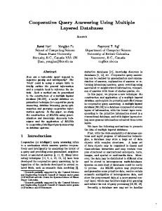
Figure 1: An example navigation task by a formation of mobile robot
T
1 Introduction There has been many researchs[6], [2], [4] in the field of multiple mobile robot, and one of the tipical tasks for multiple mobile robot is navigation by formation of multiple mobile robots (Fig.1). In such case, it is required to synchronize their action timing and positioning functions. In particular, tasks where a team of robots operates in close, need to be tied with single time base and datum reference to avoid collisions with each other. A time base matching is rather easy if an inter robot communication system is established, and mseveral technologies of communication systems are already available. self-positioning is possible by using any of three methods such as via localize themselves by individually, utilize dedicated sensors measuring relative position of robots, and comparing measuring results of same environment among multiple robots By using a suitable localizing method like the one proposed in[1] in each robot, datum reference can be matched successfully. Also previous knowledges of target environment is needed to apply this strategy. Robots equipped with sensors which measures relative position and pose[3] are free from this datum reference sharing problem. In this method, sensor systems required to have the ability to recognize individual robot. Eventhough, this method tends to be of high cost. In This paper, we propose a framework for datum reference sharing in a team of robots, which does not need any previous knowledge of its environment. In addition it can be implemented by using sensors of moderated cost.
2 Sharing a coordinate system To take an illustration, let’s think about controlling a team of robots by using a remote controller. The remote controller ex-
θB
θA PB PA
Figure 2: Coordinate system matching
presses the intention of an operator represented on a single coordinate system, which an operator has assumed. If each robot does not have a common datum reference and defines their coordinate system previously, it is not possible to make up a useful motion. The same problem happens in case of coordinating a cooperative motion of multiple robots. Originally this problem can be considered that there is not datum reference. Measuring a same object in an environment by a robots team, and by using object measurements as an common datum reference, thus all robots will be able to define single definitions of a common shared coordinate system. The system we propose in this paper, is able to measure object of an environment, and by comparing measured results, it also defines a shared coordinate system.
3 Strategy Two robots named RA and RB , which measure position and pose of a same landmark, based on a common coordinate system, including position of landmarks(PA , PB ) as well as
pose of those given landmarks(θA , θB ) (see fig.2). If both robot’s coordinate systems have same definition, then resulted measurements(PA and PB , θA and θB ) are supposed to have same values. On the other hand, if two robots have different definitions of the coordinate system, then resulted measurements difficulty can be matched. It means that small differences of measured position and pose represent a difference of each robot’s coordinate system definition. Following affine transformation T that transforms a coordinate system from RB into RA .
Ã
T =
cos θ sin θ 0
− sin θ cos θ 0
PA x cos θ + PA y sin θ + PB x PA y cos θ + PA x sin θ + PB y 1
y
r2
R2
Robot’s Trajectory
P 2 Robot
P1
!
ER P
r1 R1 Wall
O
x
RA = T R B where θ = θB − θA By means of this transformation T, it is possible to redefine a coordinate system of RB and make possible two robots to share a same coordinate system as result. This method does not assume the existence of an absolute coordinate system tied to an environment. Also, this method does not require any information of the environment in advance, robots will temporaly make usage of object’s information in the environment, which usually does not appear on conventional maps. When sensors on robots don’t have any ability to measure all 3 degrees of freedom, unique transformation T could not be determined. In this case, some number of constraint can be established, which will depend on the number of calculated degree of freedom. Considering these constraints and redefining a coordinate system in order to satisfy their differences between both coordinate systems, ambiguity can be reduced.
of the robot and anti-clockwise direction is set to plus. Using −−−→ −−−→ components of vectors P1 R1 and R1 R2 are expressed as follows: ´ ³ −−−→ r1 cos φ (2) P1 R 1 = r1 sin φ −−−→ R1 R 2 =
³
x2 + r2 cos φ y2 + r2 sin φ
To demonstrate that our proposed system can be implemented just by using low cost sensors, we utilized mobile robots equipped with ultrasonic range sensors. Although ultrasonic range sensors only have the single ability to measure distances to closest objects in the sight of them. Therefore it is possible to determine distance to the object as well as its direction if multiple measurements from different positions are matched, assuming that reference objects are flat walls. In result, one degree of freedom of position and pose of a wall are hopefully measured.
4.1 Landmark measurement As shown in Figure 3, let us consider that a couple of range data r1 , r2 are obtained by ultrasonic sensors which are fitted on the left side of the robot when the robot was located at P1 (x1 , y1 ), P2 (x2 , y2 ), respectively. If these range data were originated from the same flat wall, then the reflection points on the wall should be on the intersections of the flat wall and two perpendicular lines through P1 , P2 . Because ultrasonic waves are reflected specularly over the flat wall surface. We call these points Estimated Reflection Point (ERP)[5]. Now, we name −−−→ −−−→ two ERP as R1 and R2 . The vectors P1 R1 and R1 R2 are perpendicularly, then the inner product of these vectors should be 0 as shown by the following equation. (1)
The angle φ denotes a direction of the ultrasonic reflection and 0 degree is set on a direction of x-axis of the coordinate system
´
³
−
x1 + r1 cos φ y1 + r2 sin φ
´
(3)
By substituting equations (2) and (3) for equation (1), φ is calculated as follows.
!
Ã
π φ = − α ± arccos 2
4 Implementation
−−−→ −−−→ P 1 R1 · R1 R2 = 0
Figure 3: Configuration for the calculation of ERP. r1 , r2 are ranged data from robot’s position P1 , P2 , respectively. When these ranged data originated from the same flat wall, ERP R1 , R2 are on the intersections of the flat wall and two perpendicular lines through P1 , P2 .
p
−(r2 − r1 ) (y2 − x2 )2 + (x2 − x1 )2
(4)
Where, α is the angle that satisfies the following relations. sin α = p
x2 − x1 (y2 − y1 )2 + (x2 − x1 )2
cos α = p
y2 − y1 (y2 − y1 )2 + (x2 − x1 )2
(5)
(6)
After the calculation of the value φ as mentioned above, we can determine the position of the two ERP corresponding to a couple of ultrasonic range data. Therefore, resulted ERPs are calculated with assumption that they are on a same flat wall, it is required to confirm that ERPs are really on a same flat wall. Firstly, making a group of ERPs that found sequentially and fit a line segment using leastsquares method. If one of ERP in the group is originated from an object other than a same flat wall, distance between the ERP −−−→ and the line will be larger, and also a vector P1 R1 and the line will not meet at right angles. In such case, the ERP group can not be considered that are originated from a same flat wall. An ERP group passes tests, can safely be considered which is a part of flat wall in an environment. Resulting ERP group represents one degree of freedom of position and pose of a flat wall.
4.2 Managing landmark information At each event when a robot finds a flat wall, the robot itself notifies information that a wall has been detected to all robots.
wall
baring direction difference
difference of direction Robot
Figure 4: A pair of wall and matching operations.
Every robot stores reported information in its database. If received information is announced by itself, then matching wall information is searched from other robots information and if received information comes from other robot, matching wall information is searched from information announced by itself. Old information in a database is useless, because the common coordinate system continuously and gradually accumulates odometry errors and changes by itself. Thus such information are purged from a database when they aged enough.
Figure 5: A mobile robot YAMABICO
4.3 Find matching walls Examining a transformation for coordinate redefinition which can be calculated as described later, a pair of walls is determined if they are the same wall in an environment. Following conditions are examined.(see Fig.4.) • A baring direction difference of two walls is less than a threshold. • A difference of distances being from robot to each two walls is less than a threshold. • Two walls are intersected if a coordinate system is redefined.
Figure 6: Experimental Environment
4.4 Redefining a coordinate system Redefining a coordinate system to match a found wall and a reference wall. In a resulting new coordinate system, two walls could be measured at a same position and pose. At first, rotating around a robot’s current position to match a baring direction of two walls. This operation is equivalent as changing robot’s direction. Then translate to direction of normal vector of wall for a difference of distances that are from robot to each two wall. Therefore the coordinate redefining system works independent from robot’s main decision making system, when a redefinition occurs, position estimation of robot will jump noncontiguously. This asynchronous event can be a problem. To avoid this, a coordinate system redefinition events are notified to a main decision making system.
4.5 Priority of reference A pair of matching walls is found on two robots simultaneously. To decide which robot performs a coordinate system redefinition, priority of reference of each robot is assigned in advance. A priority of reference is a concept to avoid reference loop and it is represented by unique integer value mapped to each robot. When matching wall is found, a robot which has lower priority of reference performs a coordinate redefinition to match
its coordinate system to higher priority robot. A lower priority robot need to redefine its coordinate system more time than higher priority robot. Accordingly, the robot which has highest priority of reference does not redefine its coordinate system and becomes as the reference coordinate system holder.
5 Experiments We implemented the system and performed experiments to verify its efficiency. In this experiment, a main decision making system which cut off torque of wheels and dedicate to record estimated position on its coordinate system is arranged. A human drags two robot around the real environment and put them into a specified point. If two robots share a common coordinate system, relative estimate position at specified point should be same as in real world.
5.1 Robot system This experimental system has been build on a mobile robot YAMABICO(see fig.5). Functions in low level control layer such as motor servo control, position estimation by odometry, ultrasonic range finding are implemented on function mod-
ules that has Transputer as processor on each module[7]. All other functions such as main decision making and wall detecting with processing ultrasonic range data are implemented on a notebook PC. Notebook PCs are equipped with wireless LAN and utilize it for inter robot communication. The experimental system consists of following two main software modules. The first is the wall-detector, which utilize ultrasonic range finder and odometry to observe surrounding environment and detects flat walls. The second is the manager which collects and administrates all information about walls detected by robots. The manager searches for matching wall whenever a new wall is detected, and if found, it performs coordinate system redefinition and notify an event to main decision making system and the wall-detector. For matching wall decision, 50cm for distance threshold and 20 degree for angle threshold are used in this experiment. The wall-detector discards all information about on going calculation of ERPs and walls when an coordinate system redefinition event has been notified while these calculation depends on estimated position. A main decision making system operates independent from the manager and the wall-detector except about event notification. As mentioned before a main decision making system do nothing but logging robots state in this experiment.
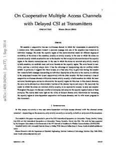
5.2 Results In this experiment one real robot and a virtual robot operate simultaneously. A virtual robot is a PC connected to a same LAN as notebook PC equipped by the real robot. A virtual robot utilize state log of a real robot to emulate a second robot. The proposed system exchanges information of detected walls, therefore virtual robot can be considered enough good equivalent to a real robot. To achieve a state log for a virtual robot, a real robot has dragged between 2 points that are start point and goal point, in advance of actual trial. Fig. 6 is an experimental environment. There are some flat walls and also some non flat objects. The start point is at end of the corridor appeared right hand side on Fig.6. Fig.7 shows estimate positions of a real robot and virtual robot that are equivalent to estimate positions of first trial by a real robot. The left graph shows a result without the proposed system, and the right graph shows a result with the proposed system enabled. Results show clear difference of estimate position at goal point between a result with and without the proposed system. Without sharing common coordinate system, distance of estimate positions at goal point between real and virtual robot is about 30cm. With sharing common coordinate system distance of estimate positions at goal point is less than 10cm. Also noncontiguous point of estimate position can be found on top side of the graph. Fig.8 shows a same result but zoomed into a particular point.
6 Summary The framework which shares a common coordinate system among a team of mobile robots has been described. Utilizing ultrasonic range finder with a flat wall detection algorithm, one of the framework has been implemented. The implementation uses a flat wall in an environment to calculate difference of coordinate system definition among robots and it automatically correct a difference. The experimental result shows its functionality. As a future work, we will integrate this system into the programming framework of multiple mobile robot, which is
Virtual Real 0
Detected walls
-1000
-2000
-3000
-4000
-5000
0
-1000
-2000
-3000
-4000
-5000 -500
0
500 1000 1500 2000 2500
Figure 7: Experimental result. Upper:independent 2 robots, Lower:2 robots with coordinate matching system.
currently developed. With the resulting programming framework, it will be easier for programming multiple mobile robot such as formation and exploration of environments routines.
Acknowledgements I would like to express my gratitude to Mr. Edgar Martinez from University of Tsukuba for his support for writing this paper.
References [1] M. Betke and K. Gurvits. Mobile robot localization using landmarks. In Proceedings of the IEEE International Conference on Robotics and Automation, volume 2, pages 135–142, 1994. [2] Jakob Fredslund and Maja J Mataric. Huey, dewey, louie, and gui – commanding robot formations. In Proceedings of the 2002 IEEE International Conference on Robotics & Automation, May 2002.
Virtual
0
Real -200
Detected walls
-400
-600
-800
-1000
-1200
-1400 0
500
1000
1500
2000
2500
Figure 8: Experimental result of 2 robots with coordinate matching system(zoomed).
[3] A. Howard, M. Matari, and c Sukhatme. Localization for mobile robot teams: A distributed mle approach, 2002. [4] Aaron Khoo and Ian Douglas Horswill. An efficient coordination architecture for autonomous robot teams. In Proceedings of the 2002 IEEE International Conference on Robotics & Automation, May 2002. [5] Akihisa Ohya Takashi Yamamoto, Shoichi Maeyama and Shin’ichi Yuta. An implementation of landmark-based position estimation function as an autonomous and distributed system for a mobile robot. In Proceedings of the 1999 IEEE/RSJ International Conference on Intelligent Robots and Systems, pages 1141–1148, Oct. 1999. [6] Richard T. Vaughan. Exploiting task regularities to transform between reference frames in robot teams. In Proceedings of the 2002 IEEE International Conference on Robotics & Automation, May 2002. [7] Shin’ichi Yuta. Autonomous self-contained robot ‘yamabico’ and its controller architecture. In Third Australia National Conference on Robotics, June 1990.