Titov 1996), and in particular separator reconnection is the fourth prime candidate for coronal heating. Numerical experiments have been conducted on this ...
The Astrophysical Journal, 624:1057–1071, 2005 May 10 # 2005. The American Astronomical Society. All rights reserved. Printed in U.S.A.
CORONAL HEATING AT SEPARATORS AND SEPARATRICES E. R. Priest, D. W. Longcope,1 and J. Heyvaerts2 Mathematics Department, St. Andrews University, St. Andrews, KY16 9SS, UK Receivved 2004 August 24; accepted 2005 January 31
ABSTRACT Several ways have been proposed for heating the solar corona by magnetic reconnection in current sheets, depending on the nature of both the coronal magnetic field and the photospheric driving. Two ways that have recently been considered involve the formation of such current sheets either along separatrices (surfaces that separate topologically distinct regions) or along separators (intersections of separatrices linking one null point to another). The effect of slow photospheric motions on complex coronal magnetic configurations will in general be to generate three forms of electric current, namely, nonsingular distributed currents, singular currents on separatrices and singular currents on separators. These currents are not mutually exclusive but will in general coexist in the same configuration. The aim of this paper is to compare energy storage and heating that occurs at separatrices and separators. We use reduced MHD to model coronal loops that are much longer than they are wide, and we construct a series of examples for the formation of current sheets along separatrices and separators. We deduce that coronal heating is of comparable importance at separatrices and separators. Separatrices are twice as effective for observed small footpoint motions, while separators are twice as effective in the initial build-up of a new flux domain. Subject heading gs: magnetic fields — MHD — plasmas — Sun: corona — Sun: magnetic fields
1. INTRODUCTION
their footpoints ( Longcope 2001; Longcope & Klapper 2002). Such equilibria have potential magnetic fields in each domain and current sheets along the separators. The theory has been applied to solar flares (Longcope & Silva 1998) and X-ray–bright points (Longcope 1998; Longcope & Kankelborg 1999; Longcope et al. 2001), and also time-dependent formation of a sheet along a separator in reduced MHD has been modeled by Longcope & Van Ballegooijen (2002). Although separator reconnection is an excellent source of heating, there are two other candidates when complex coronal fields evolve through a series of equilibria in response to photospheric motions. The fifth candidate is that within each domain the resulting magnetic fields may well be nonlinear force-free rather than potential and so can relax by turbulent reconnection to a lower energy state (Heyvaerts & Priest 1984, 1992; Van Ballegooijen 1985; Gomez & Ferro Fontan 1988; Browning et al. 1986; Vekstein et al. 1991; Nandi et al. 2003). The sixth coronal heating reconnection candidate, which we shall here be comparing with separator current sheets, is that in general current sheets can also form along the separatrix surfaces that bound each domain. Indeed, the Coronal Tectonics Model of coronal heating (Priest et al. 2002) includes the effects of heating at both separators and separatrices. Furthermore, it suggested that two factors enhance substantially the effectiveness of such heating. The first is that the photospheric magnetic field is concentrated in discrete fragments, and so there will be separatrix surfaces at the boundaries of the coronal flux that arises from each fragment and separators will be located where these separatrices intersect. Second, each subtelescopic fragment is likely to have a flux of only 3 ; 1017 Mx, so that there are enormous numbers of them and the coronal magnetic field is incredibly complex. For example, each of the very fine TRACE loops is likely to consist of 10 much finer loops with at least a hundred separatrices and separators, while each X-ray– bright point comprises a hundred such elementary loops. Thus, in the Coronal Tectonics scenario the corona is full of a web of myriads of current sheets continually forming and dissipating. Indeed, a recent analysis of the magnetic field in the quiet Sun by Close et al. (2004) has deduced the magnetic structure from a sequence
The enigma of coronal heating represents one of the most challenging problems in astrophysics at the present time. A major class of mechanisms for heating the corona involves threedimensional magnetic reconnection in current sheets (e.g., Priest & Forbes 2000), but at least six reconnection models have been proposed. The first is simple reconnection at coronal null points driven directly by photospheric motions. For example, X-ray– bright points are thought to occur by the interaction of separate flux systems either by emergence of new flux or by cancellation of flux (Priest et al. 1994; Parnell et al. 1994; Buchner et al. 2004). The second model is Parker’s classical model of topological dissipation in which complex braiding motions of photospheric footpoints cause current sheets to grow in the corona ( Parker 1972, 1981, 1994). A third model is binary reconnection (Priest et al. 2003) in which the relative motion of pairs of magnetic fragments in the photosphere drives reconnection directly, causes magnetic waves to propagate and dissipate, and also builds up nonlinear force-free fields that subsequently relax. Several distinct types of reconnection are associated with null points, namely, spine, fan, and separator reconnection (Priest & Titov 1996), and in particular separator reconnection is the fourth prime candidate for coronal heating. Numerical experiments have been conducted on this possibility (Galsgaard & Nordlund 1997; Parnell & Galsgaard 2004), and the way in which it operates in the corona has been studied in detail by Longcope and coworkers, as follows. Having showed how a current sheet may form along a separator (Longcope & Cowley 1996), a stick-slip model for reconnection was developed together with the concept of a Minimum-Current Corona (Longcope 1996). The assumption is that, after slow motions of the photospheric footpoints, the corona relaxes to a flux-constrained equilibrium in which the magnetic fluxes within each domain are conserved but the field lines within each domain can slip through the plasma or move 1 2
Physics Department, Montana State University, Bozeman, MT 59717. Observatoire, 11 Rue de l’Universite´, F-67000 Strasbourg, France.
1057
1058
PRIEST, LONGCOPE, & HEYVAERTS
Vol. 624
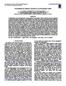
Fig. 1.—Formation of a separator current sheet along the junction of four topologically distinct domains in a three-dimensional model with (a) one photospheric plane and (b) two photospheric planes.
of observed magnetograms and has deduced that the coronal field is continually reconnecting much more often than expected— indeed, the time for all field lines in the quiet-Sun corona to reconnect is only 1.4 hr. It should be stressed that separator current sheets and separatrix current sheets are not mutually exclusive constructs but usually coexist within the same magnetic configuration. Separator sheets tend to be produced by motions that are directed toward or away from separator curves so that they are trying to drive reconnection there. Separatrix sheets, on the other hand, are formed by shearing motions on either side of a separatrix surface. Subjecting any complex coronal configuration to slow motions at a line-tied photospheric boundary will in general generate three forms of electric current in the overlying corona, namely, (i) distributed or volume currents, which are nonsingular and usually in the low-beta corona are force-free; (ii) singular currents along separator curves; (iii) singular currents along separatrix surfaces. Boundary motions can be carefully designed to generate one kind of current alone but such motions are unlikely to be generic. For example, the flux-constrained equilibrium theory of Longcope (2001) assumes boundary motions carefully constructed to produce only separator currents. The volume currents are much weaker than the other two forms and so tend to dissipate very slowly, although resulting small-scale MHD turbulence can be an effective means of heating. Estimating the relative effectiveness, however, of separator and separatrix heating is nontrivial, since in general, although the separatrix currents cover a much larger surface area, the separator current densities may well be larger due to focussing at a separator. Our aim here is to compare the relative effectiveness of separators and separatrices in coronal heating. Section 2 deduces the general properties of separator current sheets, showing how the electric current, sheet dimensions, reconnected flux, energy release, and electric field depend on the source displacement and reconnection time. Section 3 gives examples in reduced MHD of the local formation of separatrix and separator sheets. Finally, x 4 compares the effectiveness of separator and separatrix heating in a coronal loop. 2. BASIC PROPERTIES OF SEPARATOR CURRENT SHEETS 2.1. Electric Current and Dimensions Following the same spirit as Longcope (2001), let us first estimate the basic properties of a current sheet that forms with
length Ls , width 2L and thickness 2l along a separator that exists at the junction of four domains, as shown in Figure 1. Consider a plane perpendicular to the current sheet ( Fig. 2) and suppose that the field Be at a large distance Le is moved toward the separator by a given distance �. If there were instantaneous reconnection, the flux that would be reconnected is simply ð1Þ
4 ¼ Be �Ls ;
where Ls is the length of the separator out of the plane of Figure 2. However, we suppose that instead a current sheet forms along the separator and there is no reconnection. Suppose the field near the separator initially has local field components Bx ¼
Be y; Le
By ¼
Be x; Le
Bz ¼ B0 ;
whose x- and y-components may be written in terms of the complex variable Z ¼ x þ iy as By þ iBx ¼
Be Z: Le
Then, after the current sheet has formed, it may be represented as a cut in the complex plane from Z ¼ �L to Z ¼ L (Green 1965) and described by By þ iBx ¼
Be 2 (Z � L2 )1=2 : Le
ð2Þ
From equation (2) we may deduce several properties of the sheet. First of all, by evaluating it at (x; y) ¼ (0; 0þ) or (0; 0�) we find the magnitude (Bi ) of the inflow field at the point of symmetry on either side of the sheet as Bi ¼
Be L: Le
ð3Þ
Second, since the fields on the top and bottom sides of the sheet from equation (2) at (x; 0þ) and (x; 0�) for jxj < L are Bx ¼ �
Be 2 (L � x 2 )1=2 ; Le
No. 2, 2005
CORONAL HEATING AT SEPARATORS AND SEPARATRICES
1059
Fig. 2.—Magnetic field in a plane perpendicular to the separator (a) in the initial potential state and (b) after a current sheet has formed without reconnection due to a displacement � of the initial field Be at distance Le from the separator.
the current in the sheet at distance x along it is J (x) ¼
Equating this to equation (1) gives the following transcendental relation for the dimensionless sheet length (L/Le ) in terms of the dimensionless flux displacement (�/Le )
1 2Be 2 ½ Bx (x; 0þ) � Bx (x; 0�)� ¼ (L � x 2 )1=2 : � � Le
Integrating this from x ¼ �L to x ¼ þL gives the total current (I ) in the sheet in terms of Bi (eq. [3]) as � ð4Þ I ¼ Bi L: � Thus, eliminating Bi between equations (3) and (4) gives a relation between the current (I ) and the half-width (L) of the sheet as 2
I L ¼ ; Ie L2e
ð5Þ
� �1=2 L 2�=Le ¼ : Le �log (L=Le )
ð6Þ
The solution of this equation is plotted in Figure 3. Once L/Le has been determined from equation (6), the current (I ) follows from equation (5). In the limit when �/Le T1, approximate solutions for L and I are � �1=2 L 4�=Le ¼ Le �log (�=Le )
ð7Þ
where Ie ¼
�Le Be �
is a characteristic current. Furthermore, the field Bx (0; y) along the y-axis is Be y/L initially and Bx (0; y) ¼
Be 2 (L þ y 2 )1=2 Le
after the sheet has formed. Integrating the difference between these two along the y-axis gives another expression in addition to equation (1) for the extra magnetic flux associated with the formation of the current sheet, namely, Z Be Le pffiffiffiffiffiffiffiffiffiffiffiffiffiffiffi L2 þ y 2 � y dy 4 ¼ Ls Le 0 qffiffiffiffiffiffiffiffiffiffiffiffiffiffiffiffiffiffiffiffi � Ls Be h 2 L loge Le =L þ 1 þ L2e =L2 ¼ 2Le qffiffiffiffiffiffiffiffiffiffiffiffiffiffiffi �i þ Le L2 þ L2e � L2e ; or, in the limit when LTLe , 4 ¼
Ls Be L2 Le loge : 2Le L
Fig. 3.—Current sheet length (L) as a function of the flux displacement (�) together with the approximate solution (eq. [7]) shown dashed, where Le is the external ambient scale length.
1060
PRIEST, LONGCOPE, & HEYVAERTS
Vol. 624
and I 4�=Le : ¼ Ie �log (�=Le ) 2.2. Energy Release, Voltage, and Electric Field During Reconnection Now, during three-dimensional reconnection, a change in flux is associated with an electric field (Ek ) and an associated voltage (V ) along the separator. This may be estimated by the following thought experiment. Suppose the flux sources are moved through a distance � and that the field responds by an ideal motion to a new equilibrium containing a current sheet with current I (which we have already estimated in terms of the flux � ). Then suppose the magnetic field reconnects, while the current declines from I to 0. First of all, the relation between � and voltage V may be calculated by integrating Faraday’s law over a surface bounded by the separator Z Z Z Z @B = dS ¼ � : < E = dS; @t and so, using Stokes’ theorem, Z Z Z d B = dS ¼ � Ek ds; dt or, in other words, d ¼ V: dt If our flux � takes a time �t to reconnect, therefore, � ¼ V �t:
ð8Þ
Next, the energy (�W ) released during the reconnection process can be estimated as follows in terms of the transfer (� ) of flux. It is simply 1 �W ¼ P�t; 2 where the power (P) is given by P ¼ IV and the factor 1/2 arises because the current declines from an initial value of I to zero over the course of the reconnection. Therefore, using equation (8) for V �t, we find 1 �W ¼ I� : 2
Ie L2 Be �Ls Ie Be � 2 Ls =Le �B2e � 2 Ls ¼ ; ¼ 2L2e log (Le =L) � log (Le =L)
termined from observations or from the type of reconnection operating if that were known, such as Sweet-Parker (Sweet 1958; Parker 1958) reconnection, fast reconnection ( Priest & Forbes 2000), or stick-slip reconnection ( Longcope 1996). Once �t is indeed known, three other remaining physical quantities can be determined, namely, the heating power or rate of heating P¼
ð9Þ
After substituting for I from equation (5) and � from equation (1), this becomes �W ¼
Fig. 4.—Shearing of a separatrix surface of width L0 and length Ll by a motion � to produce a current I.
ð10Þ
since Ie ¼ �Le Be /�, where L/ Le is determined by equation (6). Thus, for given values of Be , Le , Ls , and �, we have deduced the flux change (� ) from equation (1), the sheet half-width (L) from equation (6), the current (I ) from equation (5), and the heat (�W ) from equation (9). What is still unknown is the time (�t) for flux transfer by reconnection. It could in principal be de-
2�W � ¼I ; �t �t
ð11Þ
� ; �t
ð12Þ
the voltage V ¼
and the electric field along the separator Ek ¼
V : Ls
ð13Þ
2.3. Separatrix Surface The current build-up and energy release at a separatrix surface of length Ll and width L0 (i.e., the typical distance between photospheric sources) may be estimated in a similar way (Fig. 4). First
No. 2, 2005
CORONAL HEATING AT SEPARATORS AND SEPARATRICES
of all, a footpoint motion � acting on an initially vertical field (B0 ) produces a transverse component B� ¼
� B0 ; Ll
ð14Þ
and so the separatrix current sheet contains a current (I ) of 2B� L0 ; �
I¼ or, after substituting for B� , I¼
2B0 �L0 : � Ll
ð15Þ
The energy release by reconnection (if the new transverse component (B� ) is annihilated) is �W ¼
1 I� ; 2
where now � is the flux of the annihilated component B� over an area Ll L0 , namely, � ¼ B� Ll L0 or, after using equation (14), � ¼ B0 �L0 ; so that the energy release becomes �W ¼
B20 � 2 L2o : � Ll
ð16Þ
In order of magnitude we see, after substituting for Ie in equation (5), that the currents and energy release from separator (eqs. [5] and [10]) and separatrix reconnection (eqs. [15] and [16]) have similar forms and are similar in size. In order to compare the energies in equations (10) and (16), suppose that Ls ¼ Ll and Le ¼ L0 . The value of B0 is of order the main coronal field, whereas Be is a field component transverse to the main field. In order, therefore, to make a reasonable comparison between B0 and Be , we assume that Be � B0 L0 /Ll , since this is the maximum perpendicular field that would be obtained by moving the footpoints of an initially uniform field (B0 ) a distance L0 in a cell of size L0 ; L0 . The resulting ratio of energies from equations (10) and (16) is then �Wsepr � : ¼ log (Le =L) �Wsepx For separator heating to be important, the sheet width (L) needs to cover a significant fraction of the separatrix. We deduce that the formation of current sheets at separators and separatrices are likely to be equally important in coronal heating, the precise ratio of their contributions depending on the parameter values adopted. Before presenting examples of both, we shall set up the basic equations for the modeling.
1061
10 W m�2. The second case is the quiet Sun at solar maximum where we adopt corresponding values of 20 G and 300 W m�2 (i.e., 3 ; 105 ergs s�1 cm�2). Third, we consider an active region in which we assume values of 100 G and 5000 W m�2 (Withbroe & Noyes 1997). These values are similar to those obtained by Katsukawa & Tsuneta (2002), Schrijver et al. (1997), and Welsch (2002). The mean separator length (Ls ) has been estimated for the quiet Sun by constructing models of the magnetic carpet from observed magnetograms to be 60 Mm (Close et al. 2003) and, since no similar analysis has been made for active regions, we shall provisionally adopt the same value there. Then, for a flux displacement (�) of, say, 300 km, we find from equation (1) a magnetic flux transfer (� ) of 5:3 ; 1017 , 3:6 ; 1018 (i.e., 3:6 ; 1010 Wb), or 1:8 ; 1019 Mx, for ambient fields (Be ) of 3, 20, or 100 G, respectively. Next, from equation (6) and Figure 3 we can calculate the dimensionless sheet length (L/Le ) as a function of �/Le , where Le is the external scale length (which we take as 30 Mm since a width of two supergranules would seem a reasonable scale for background variations). Thus, a value � ¼ 300 km leads to a value for L/Le of 0.1, so that the sheet is 3 Mm wide. From equation (5) the current (I ) along the separator follows as 1:9 ; 108 , 1:3 ; 109 , or 6:3 ; 109 A for fields (Be ) of 3, 20, or 100 G, respectively. The corresponding magnetic fields Bi ¼ Be L / Le at the sheet are 0.3, 2, and 10 G, respectively. The energy release (�W ) in the elementary heating event associated with the flux transfer � follows from equation (9) as �W ¼ 12 I� , which becomes 5 ; 1017 , 2:3 ; 1019 (i.e., 2:3 ; 1026 ergs), or 5:6 ; 1020 W for fields of 3, 20, or 100 G, respectively. If we assume a footpoint motion (v0 ) of 0.3 km s�1 ( Hagenaar 2001), say, the time (�t) associated with the flux displacement � ¼ 300 km is then 103 s. The corresponding voltage V along the separator from equation (12) is then 5.4, 36, or 180 GV, respectively, while the electric fields (Ek ) from equation (13) are 100, 720, or 3600 V m�1, which are much larger than the typical Dreicer values (0.03 V m�1) in the corona. Finally, the power (P) follows from equation (11) and is found to be 1:0 ; 1015 , 4:6 ; 1016 (4:6 ; 1023 ergs s�1), or 1:1 ; 1018 W for fields of 3, 20, or 100 G, respectively. Dividing by the area (15 Mm)2 of a typical supergranule, say, we arise at a power per unit area of 4.8, 200 (i.e., 2 ; 105 ergs cm�2 s�1), or 5000 W m�2 for the heating in the very quiet Sun, in the quiet Sun at solar maximum or in an active region, which compare well with the observed values of 10, 300, and 5000 W m�2, respectively. 3. REDUCED MHD MODELING OF CORONAL LOOPS In order to shed light on the formation of current sheets at separators and separatrices, we follow Van Ballegooijen (1985) and Longcope & Van Ballegooijen (2002) in setting up reduced MHD models (Strauss 1976) for long, thin coronal loops. First of all, we set up the basic equations and give examples of local models of separator and separatrix sheets. Then x 4 constructs more global models in a coronal loop.
2.4. Values in the Solar Corona
3.1. Reduced MHD Equations
Using the above expressions for separator reconnection we may estimate possible values for the corona as follows. We shall consider three standard cases. The first is the very quiet Sun, where the mean field has been estimated by Harvey (1993) to be 3 G; so we shall assume here that Be ¼ 3 G (although the actual value may well be significantly larger) and that the heating rate is
A large–aspect-ratio geometry is assumed with a domain of total length Ls þ 2h much larger than its length in the x-y plane (Fig. 5). The long axis runs from z ¼ �h to z ¼ Ls þ h with the main central region from z ¼ 0 to z ¼ Ls representing the corona and two end regions representing the photospheric and chromospheric layers. Boundary conditions on the coronal dynamics are
1062
PRIEST, LONGCOPE, & HEYVAERTS
Vol. 624
3.2. Examples of Local Separator and Separatrix Sheets Consider first a magnetic field of the form � �y � x � ; ; 1 ; (Bx ; By ; Bz ) ¼ B0 a a
ð22Þ
where � represents the amplitude of the (stagnation-point) footpoint motions producing this field from the initial state B0 zˆ ( Fig. 6a). In a cylinder of radius a, say, it has a magnetic energy per unit axial distance of � � Z 2 B B20 a2 �2� dV ¼ 1þ ; ð23Þ W1 ¼ 2 2� 2� but, since it is a potential field, it is a minimum-energy state and cannot reconnect to release energy. The motions at the coronal base z ¼ 0; z ¼ Ls that produce this field are given by
Fig. 5.—Geometry of the model.
applied at the merging heights z ¼ 0 and z ¼ Ls , which represent the interfaces between chromosphere and corona. Discrete isolated magnetic sources of flux 1017 –1018 Mx representing the photospheric magnetic field are located on the end boundaries of the region. In the chromospheric layers the magnetic field arising from the photospheric sources is assumed to spread out to become an initially uniform field in the corona. In response to photospheric footpoint motions the axial field Bz ¼ B0 remains uniform, but a small perpendicular component B? ¼ Bx xˆ þ By yˆ is introduced such that B? � � B0 , where � ¼ a / Ls T1. In such a reduced-MHD ordering, the object is to determine the new equilibrium field with components that may be written in terms of a flux function ½ A ¼ A(x; y; z)� as � � @A @A ; � ; B0 ð17Þ (Bx ; By ; Bz ) ¼ @y @x such that the equation : = B ¼ 0 is automatically satisfied. Assuming the corona to have a very small plasma beta and large scale height so that the forces of plasma pressure gradient and gravity are negligible, the reduced MHD equilibrium equations for the coronal magnetic field are @A @j @A @j @j � þ ¼ 0; @ y @x @x @ y @z
ð18Þ
@ 2A @ 2A � 2 @x 2 @y
ð19Þ
where �j(x; y; z) ¼ �
�j ¼ �f (A) is a function of A ¼ A(x; y) alone and equation (19) reduces to ð20Þ
In particular, where there are no coronal currents this reduces further to Laplace’s equation @ 2A @ 2A þ 2 ¼ 0: @x 2 @y
with components Bx ¼
@� x B0 ; @z
ð21Þ
By ¼
@�y B0 : @z
Thus, if for example � vanishes at z ¼ 0, the components of the motion are �x ¼
zBx ; B0
�y ¼
zBy ; B0
and so in the plane z ¼ Ls (or indeed in any plane z ¼ constant) the streamlines are parallel to the field lines associated with the transverse field. In other words, the motions have the same form as the field lines in Figure 6, in terms of both streamline shape and direction. In order to construct a field with separatrix current sheets, we simply reverse the direction of the transverse field (eq. [22]) in the regions above and below the separatrices while keeping the same directions to the left and right, as shown in Figure 6b. The resulting field produced by shearing stagnation-point motions is � y 2 < x 2; B0 (�y=a; �x=a; 1); (Bx ; By ; Bz ) ¼ B0 (��y=a; ��x=a; 1); y 2 > x 2 ; and contains the same energy as before given by equation (23). However, this magnetic field is not potential and can reconnect and reduce to the initial state, so releasing an energy W1 � W0 , where W0 ¼ B20 a2 / (2�), namely, Wseparatrices ¼
is the z-component of the coronal current. In regions where @j/@z ¼ 0, equation (18) implies that
@ 2A @ 2A þ 2 ¼ f (A): @x 2 @y
B ¼ : < (� < B0 )
B20 2 2 (� �a ) 4�
ð24Þ
per unit axial distance. The transverse field components of the field (eq. [22]) can be written in compact form in terms of the complex variable Z ¼ x þ iy as By þ iBx ¼
�B0 Z; a
which suggested to Green (1965) the following corresponding form with a cut in the plane from Z ¼ �L to Z ¼ þL representing a separator current sheet By þ iBx ¼
�B0 2 (Z � L2 )1=2 ; a
ð25Þ
No. 2, 2005
CORONAL HEATING AT SEPARATORS AND SEPARATRICES
1063
Fig. 6.—Field lines of the transverse magnetic field (or streamlines of the associated flow) in the x-y plane, perpendicular to the main axis of the loop, showing fields with (a) no current sheets, (b) separatrix sheets, (c) a separator sheet, and (d ) separator and separatrix sheets.
as sketched in Figure 6c. Its magnetic energy in the limit when LTa is � � B20 a2 �2 � �2 �L4 þ 1þ W2 ¼ : ð26Þ 2 2� 2a 4 This field is produced by stagnation-point motions of amplitude � in the x-y plane as before, together with a converging motion toward the separator of magnitude �, which is related to L by equation (6) and which drives the formation of the separator current. When this field dissipates and reconnects, it reduces to the field (eq. [22]) and releases an energy W2 � W1 of Wseparator
B2 �2 �L4 ¼ 0 : 4� a2
ð27Þ
However, the field produced by a combination of shearing stagnation-point and converging motions toward the separator can produce current sheets both along the separatrices and the separator, as indicated in Figure 6d. The corresponding transverse field is given by By þ iBx ¼
� B0 2 (Z � L2 )1=2 a
to the left and right of the separatrices and By þ iBx ¼ �
� B0 2 (Z � L2 )1=2 a
above and below the separatrices. Its magnetic energy is W2 , given by equation (26), but now, when it dissipates, it reduces to the initial field B0 zˆ , and so the energy released is W2 � W0 , namely, � � B2 L4 Wtotal ¼ Wseparatrices þ Wseparator ¼ 0 � 2 �a 2 1 þ 4 : ð28Þ 4� a In the case LTa, we see that the separator contribution is smaller than the separatrix contribution by a factor L4 /a4 . 4. SEPARATRIX AND SEPARATOR CURRENT SHEETS IN A CYLINDRICAL CORONAL LOOP Consider a long thin cylindrical flux tube with length (LS ) much longer than its radius (a) and merging height (h) ( Fig. 5). Suppose there is initially a uniform axial magnetic field, with two flux sources at each end of the tube and that subsequently the flux sources move and generate current sheets. Figures 7a and 7b show the initial positions of the sources, with the lines joining each pair inclined to each other by an angle ��0 , say.
1064
PRIEST, LONGCOPE, & HEYVAERTS
Vol. 624
Fig. 7.—Schematic projection of magnetic field lines in a section across the coronal part of the flux tube for (a) the initial state at the end z ¼ 0 of the loop, showing the separatrix (thin solid line) that separates the field lines coming from the two sources (large dots); (b) the initial state at z ¼ LS with its separatrix (the separator is the intersection of the two separatrices); (c) the configuration after spinning and rotating all four sources, showing current sheets (thick solid curves) along the separatrices and separator; and (d ) the relaxed state after reconnection.
The field lines going to the two sources at z ¼ LS will be separated by a separatrix surface (the y ¼ 0 plane), while the field lines coming from the two sources at z ¼ 0 will also be separated by a separatrix surface that is a plane inclined at �0 to the y ¼ 0 plane. These two separatrices will intersect in a separator (the z-axis) and divide the loop up into four topologically distinct regions, in each of which all the field lines will start at the same source and end at the same source. Arbitrary motions of the sources can be decomposed into several parts, namely, a spinning of each source plus a rotation of the line joining the sources, both of which generate current sheets, together with a translation and an approach or separation of a pair of sources, which do not generate current sheets and which we shall therefore not consider. A general motion consisting of a spinning of all four sources together with a rotation of both pairs of sources will generate current sheets along both the separator and also all along the four separatrices ( Fig. 7c) together with a distributed current in each domain. Reconnection and dissipation will then lead to a relaxed state with no current sheets ( Fig. 7d), which possesses the same magnetic helicity as the stressed state. In the next section we consider the effect of spinning the sources at only one end (z ¼ LS ) of the loop, which produces a
single separatrix current sheet along the corresponding separatrix (Fig. 8a). The following section goes on to consider instead the generation of a separator current sheet by rotating the sources at z ¼ LS without spinning them ( Fig. 8b). It also compares the heating produced by separatrix and separator currents. 4.1. Separatrix Sheet Produced by Spinning One Pair of Sources As mentioned above, we here consider the creation of a straight current sheet along a separatrix in response to the ideal spinning of one pair of sources by �� ( Fig. 8a) and the subsequent relaxation by reconnection to a lower energy state (Fig. 7d). What is the resulting equilibrium magnetic field and how much energy is released when the current sheet dissipates? For the spun state, we use the reduced MHD framework described in x 3.1, in which the magnetic field components are of the form shown in equation (17) with the flux function satisfying equation (20). In particular, for simplicity we seek a spun state that is a constant current solution with A ¼ 0 on r ¼ a to @ 2A @ 2A þ ¼ �J0 ; @ x 2 @ y2
ð29Þ
No. 2, 2005
CORONAL HEATING AT SEPARATORS AND SEPARATRICES
1065
Fig. 8.—(a) Effect of spinning the sources at z ¼ LS by an angle �� is to create a distributed current and a current sheet along the corresponding separatrix surface. (b) Effect of rotating the sources at z ¼ LS by �� is to generate a current sheet along the separator.
everywhere except on the separatrix � ¼ 0 and � ¼ �, where we have taken A ¼ 0. The solution in the region (0 < � < �) above the sheet satisfying the first condition (A ¼ 0 on � ¼ 0 and � ¼ �) is a sum of J0 (a 2 � r 2 )/4 and a harmonic function H(r; �), namely ( Longcope & Van Ballegooijen 2002), A¼
1 2 J0 a � r 2 þ a 2 H(r; �) ; 4
ð30Þ
where "
# 1 X r2 r 2mþ1 H(r; �) ¼ 2 cos 2� � 1 þ c2mþ1 2mþ1 sin (2m þ 1)� : a a m¼0 ð31Þ The second condition (A ¼ 0 on r ¼ a) implies 1 X m¼0
c2mþ1 sin (2m þ 1)� ¼ 1� cos 2�;
which determines the coefficients c2mþ1 as � � 2 2 1 1 � � c2mþ1 ¼ : � 2m þ 1 2m þ 3 2m � 1
ð32Þ
The solution below the current sheet (i.e., � < � < 2�) is by symmetry just �A(r, �), with A(r, �) given by equation (30). Contours of this function are shown in Figure 9. The final relaxed state of lowest energy preserving magnetic helicity is a linear force-free field, which in reduced MHD to lowest order is a state with uniform current, having : < B ¼ �B0 zˆ , where � is constant. Its flux function therefore has the form A¼
1 2 (a � r 2 )�B0 ; 4
ð33Þ
corresponding to circular field lines in an x-y plane with a field B� ¼
1 r�B0 : 2
1066
PRIEST, LONGCOPE, & HEYVAERTS
Vol. 624
The spun state consists of two flux tubes with uniform current density J0 over their D-shaped cross sections. In the reduced MHD scaling they are each a constant-� equilibrium, with � ¼ J0 /B0 . They are separated by a flat current sheet whose current partly cancels that of the tubes, so the equilibrium as a whole is not constant-�. According to expression (39), Taylor relaxation to a constant-� solution reduces the value of � within the tubes by 62% from J0 / B0 . Furthermore, J0 may itself be written in terms of the angle (��) through which each source is spun by equating the magnetic helicity (eq. [37]) to the helicity 2
�� 2 F 2� S
due to two sources each of magnetic flux FS ¼ 12 �B0 a2 rotated through an angle ��. The result is J0 ¼ 1:32 Fig. 9.—Contours of the flux function A(r, � ) for the spun state (eq. [30]).
The coronal part of the flux tube has a relative magnetic helicity ( Finn & Antonsen 1985) Z Hm ¼ (A þ A0 ) = (B � B0 ) dV ; where B0 ¼ B0 zˆ is the corresponding potential magnetic field and A0 is its vector potential. For our problem this reduces to Z Z @A 2 r dr d� LS B0 ; Hm ¼ � ð34Þ @r which may be written (after integrating by parts and using the fact that A ¼ 0 on r ¼ a) as Z Z Hm ¼ 2rAdr d� LS B0 : ð35Þ
For the spun state (eq. [30]) the magnetic helicity (eq. [34]) becomes Z �Z a rAdr d�; ð36Þ Hm ¼ 2B0 LS 0
0
where A is given by equation (30). After some work evaluating the infinite sums, it becomes � � � 4 4 � Hm ¼ a J0 ð37Þ LS B0 : 2 � For the relaxed state equation (33) the magnetic helicity is Hm ¼
� �LS a4 B02 ; 4
ð38Þ
and so equating the magnetic helicities (eqs. [37] and [38]) under the assumption of magnetic helicity conservation during reconnection determines the value of � in the relaxed state as � � 16 J0 : ð39Þ �¼ 2� 2 � B0
��B0 : LS
ð40Þ
Next, let us estimate the energy release during relaxation. The excess magnetic energy (WS ) above potential of the spun state is given by Z 2�WS ¼ ( :A)2 dV ; which may be rewritten, after using a vector identity and invoking the divergence theorem, as Z 2�WS ¼ : = (A:A) � :2 A : A dV Z Z ð41Þ ¼ n = A:AdS :2 A : A dV: For our flux tube the surface integral vanishes and :2 A ¼ �J0 ; so that the expression for the magnetic energy reduces to Z 2�WS ¼ J0 AdV : But we have already shown that the magnetic helicity Z Hm ¼ 2AB0 dV has the same form as this, and so 2�WS ¼
J0 Hm ; 2B0
where Hm is given by equation (36). For the spun state (eq. [30]) the energy therefore becomes � � a4 J02 � 4 � ð42Þ LS : 2�WS ¼ 2 � 2 For the relaxed state (eq. [33]), on the other hand, with � given by equation (39), the magnetic energy (Wf ) is given by Z Z 2� Z a 1 2 2 r � r dr d� B20 LS ; 2�Wf ¼ B2� dV ¼ 0 0 4
No. 2, 2005
1067
CORONAL HEATING AT SEPARATORS AND SEPARATRICES
or, integrating and substituting for �, � � 2 4 2 � 4 � 2�Wf ¼ a J0 LS : � 2 �
ð43Þ
with no currents. We follow this approach, which has proved to be highly useful, in what follows. Thus, we require that the twodimensional function, Acs (r; �), be harmonic over the entire disk except for a current sheet extending along the x-axis from �L to L. We choose the helical pitch to be
Dividing equation (41) by equation (42) gives the ratio of WS to Wf as WS 1 ¼ ¼ 2:64: 2 � 16=�2 Wf Also, subtracting equation (42) from equation (41) gives the heating produced during relaxation as Wh ¼ WS � Wf ¼
(8=� 2 � 1=2)(�=2 � 4=�) 4 2 a J0 L S : 2�
ð44Þ
Alternatively, these may be written in terms of the volume VS ¼ �a2 LS of the coronal flux tube and either the magnetic field BS ¼
4a J0 3�
at the origin above the current sheet (i.e., at r ¼ 0þ, � ¼ �/ 2) in the spun state or the angle (��) through which each source is spun. The result is B2 a2 B 2 WS ¼ 0:263 S VS ¼ 0:147(��)2 2 0 VS ; 2� LS 2� B2 a2 B2 Wf ¼ 0:1 S VS ¼ 0:056(��)2 2 0 VS ; 2� LS 2�
ð45Þ ð46Þ
and Wh ¼ 0:163
B2S a2 B 2 VS ¼ 0:091(��)2 2 0 VS : 2� LS 2�
ð47Þ
4.2. Separator Sheet Produced by Rotating One Pair of Sources Let us now consider instead the creation of a helical current sheet of width 2L along the separator by rotating the sources at z ¼ LS through �� without spinning them ( Fig. 8b) and the subsequent relaxation by reconnection to a lower energy state ( Fig. 7d ). Again we need to determine the resulting equilibrium magnetic field and the energy that is released when the current sheet dissipates. As before, we use a reduced MHD framework with the magnetic field components having the form shown in equation (17) and the flux function satisfying equation (20). In this case we seek a helical equilibrium A(r; �; z) ¼ Acs (r; � � qz þ �0 ):
ð48Þ
where q is the pitch of the helix. As mentioned in the introduction, in general a motion of flux sources without reconnection leads to the generation of currents both in the volume and along separatrices and separators. In view of the complexity of calculating such fields, Longcope (2001) has for simplicity introduced the notion of a flux-constrained equilibrium, in which only the currents along the separators are taken into account, so that there are no current sheets along separatrices and the volumes between the separatrices are occupied by potential fields
q¼
�0 þ �� LS
ð49Þ
in order that the current sheet lie on the positive separatrix, � ¼ ��0 at z ¼ 0, and on the negative separatrix, � ¼ ��, at z ¼ LS . The current sheet is on both separatrices simultaneously, so it is a separator sheet. [Had the sources been rotated in the negative sense, �� < 0, the helical sheet would have had a negative (lefthanded) pitch q ¼ �(� � �0 � ��)/LS . We hereafter take �� > 0 for concreteness.] In order to be an equilibrium the full magnetic field B0 zˆ þ 9A ; zˆ must be tangent to the current sheet. This means that field lines at the current sheet must have the same helical pitch as the current sheet itself. The radial field components from opposite sides of the sheet cancel out, so the mean field within the sheet is purely helical. Since the current density depends on z and � only in the combination � � qz, the requirement for equilibrium is that B = :(� � qz) ¼ 0 ¼
B� � qB0 r
at the location of the current sheet. This implies that the azimuthal component of the field at the current sheet must be B� ¼ �
@A ¼ B0 qr; at � ¼ qz � �0 ; r < L: @r
ð50Þ
Solutions which are harmonic and satisfy this condition together with Acs ¼ 0 at r ¼ a have been found by Longcope & Van Ballegooijen (2002). Since it is harmonic outside the current sheet, the function Acs (x; y) can be written compactly in ˆ )] of the comterms of a dimensionless complex function [F(Z plex variable Z ¼ x þ iy as � � 1 2ˆ i� ð51Þ Acs (r; �) ¼ Re qB0 L F(re ) : 2 The components of the magnetic field are then found from the complex expression 1 By þ iBx ¼ � qB0 L2 Fˆ 0 : 2 ˆ The function F(Z) should be analytic except along a branch cut between Z ¼ �L and Z ¼ L, where its derivative should have the real part Re½Fˆ 0 � ¼ �2 x /L2 in order to satisfy equation (50). In cases where the current sheet is very small compared to the cylinder, LTa, the complex function can be found in terms of the complex potential of the Green-Syrovatskii current sheet (Green 1965; Syrovatsky 1971). The Green-Syrovatskii solution has no field normal to the sheet and asymptotes to an X-type field far from the current sheet. Condition (50) and Acs (a; �) ¼ 0 can both be satisfied by subtracting the X-type field from the GreenSyrovatsky field, yielding ( Longcope & Van Ballegooijen 2002) rffiffiffiffiffiffiffiffiffiffiffiffiffiffi pffiffiffiffiffiffiffiffiffiffiffiffiffiffiffiffi ! 2 Z Z Z þ Z 2 � L2 Z2 ˆ )¼ F(Z � 1 � ln ð52Þ � 2: 2 1=2 L L L 2ae
1068
PRIEST, LONGCOPE, & HEYVAERTS
Vol. 624
Fig. 10.—Flux functions Acs (r; �) generating the flux constrained equilibria in the cases LTa (left) and L ¼ a (right). Plotted are the contours of Acs (thin lines) and the current sheet extending between x ¼ �L and x ¼ L.
This function, whose contours are plotted in Figure 10a, is analytic except for a branch cut between branch points Z ¼ �L and Z ¼ L, which produces the singular current density pffiffiffiffiffiffiffiffiffiffiffiffiffiffiffi �92 Acs ¼ 2qB0 L2 � x2 �( y):
ð53Þ
The field generated by this potential maps the separatrices from one end of the cylinder to the other. The helical pitch q has been chosen to assure that the two separatrices coincide along the current sheet itself: it defines the field’s separator. In the region beyond the sheet, r > L, there are distinct separatrices dividing the volume into four flux domains, as shown in Figure 11a. It is a tenet of Flux Constrained Equilibrium theory (Longcope 2001) that the net flux of each domain match the flux it had prior to the rotation of the sources. The wedge �� swept out by the negative separatrix must be offset by the area between the dashed line and the positive separatrix in Figure 11b. It is this requirement which relates the rotation angle �� to the length of the current sheet L. Using once more the fact that LTa this constraint can be cast as the transcendental equation ( Longcope & Van Ballegooijen 2002) � � 2 �� �� L2 a 2 ¼ ln e 2 2 � 1 ; �0 þ �� 2a2 L
ð54Þ
relating ��/�0 to L/a as illustrated in Figure 12b. This differs slightly from expression (62) given in Longcope & Van Ballegooijen (2002), owing to a different choice of the location at which to match asymptotic functions. Wephave ffiffiffi chosen to match the functions at r ¼ L rather than r ¼ L/ 2. The advantage is that equation (51) now gives L ¼ a in the limiting case �0 ! 0, a case that we consider below. Further details can be found in Longcope & Van Ballegooijen (2002). It is also possible to find the complex potential in the opposite limit where the separator current sheet extends across the entire cylinder, L ¼ a. In this case the two separatrices must be entirely coincident with one another and therefore with the separator. This is only possible when �0 ¼ 0 (corresponding to the limit ��/�0 ! 1). The harmonic function satisfying condition (50) over the entire range �a < x < a is Acs ¼ �12 qB0 H(r; �), where the function H is the same one used for the spun state and is
given in equation (31). The corresponding complex potential is (Longcope & Van Ballegooijen 2002) � � � 2 2 2 ˆF(Z ) ¼ 1 � Z þ i 2 � a � Z a2 � Z 2 a2 � � � �� aþZ 2i a Z þ ; ln þ ; a�Z � Z a which is contoured in Figure 10b. The excess magnetic energy (WR ) above potential of the rotated state has the same form as equation (41) and with A vanishing on the boundary as before and this time satisfying equation (48). We can write the current density of the current sheet in the form �:2 Acs ¼ qB0 LK(x)�( y);
ð55Þ
where K(x) ¼ Im½LFˆ 0 (x þ i0)� gives �Bx just above the current sheet. This dimensionless function takes the form 8 qffiffiffiffiffiffiffiffiffiffiffiffiffiffiffiffiffiffiffiffi 2 > > LTa; < 2 1 � (x=L) ; � � K(x) ¼ 16 X1 1 x 2m > > ; L ¼ a; : 2 m¼0 4 � (2m þ 1) � L in each of the two limiting cases. In terms of this function the energy takes the form Z
2�
Z
a
2�WR ¼ LS
Acs qB0 LK(x)�( y) dr d� � Z L� 1 x2 dx Fˆ r (0) � 2 K(x) ; ¼ q2 B20 LS L4 2 L L �L 0
0
ð56Þ
ˆ after using the fact that Re½F(x)� ¼ Fˆ r (0) � x 2 / L2 along the current sheet. The dimensionless integral in expression (56) depends only on the relative size of the current sheet and can be evaluated in each of the two limiting cases Z
(
1
�1
½Fˆ r (0) � t �K(Lt)dt ¼ 2
� ln (2e1=4 a=L); 1:9512;
LTa; L ¼ a:
ð57Þ
No. 2, 2005
1069
CORONAL HEATING AT SEPARATORS AND SEPARATRICES
Fig. 12.—Plots of (a) � given by eq. (58) and (b) sheet length L/ a as functions of ��/�0 when rotating a pair of sources through an angle ��. When � < 0:147, i.e., below the dashed line, the energy produced by spinning the sources through �� exceeds that by rotating them through the same angle (�� ¼ ��).
where the dimensionless factor 8 1=2 2 2 < ln (4e a =L ) ; LTa; �¼ ln2 ½e 2 (2a2 =L2 � 1)� : 0:3105; L ¼ a;
ð59Þ
depends on ��/�0 through L/a; it is plotted in Figure 12a. The energy above the potential state injected by rotating the sources by an angle ��, without spinning, may be written in the form WR ¼ �(��)2
Fig. 11.—Plots of the separatrices and separator current sheet at the z ¼ LS plane. The separatrix between the negative sources is a straight solid line at � ¼ ��. The other separatrix is straight at the z ¼ 0 level (dashed line) but the field maps it to the solid curve at z ¼ LS . The two separatrices overlap along the separator, shown as a dark solid line of length 2L. In both panels �0 ¼ �/4. The top panel shows �� ¼ 0:16 for which L ¼ a/4; the bottom shows �� ¼ 0:29 for which L ¼ a/3.
In order to compare this energy to that of the spun state it is necessary to express L /a and q in terms of the rotation angle ��. Using equation (49) allows us to write ( (2a2 =L2 ) ln�1 ½e 2 (2a2 =L2 � 1)�; LTa; qLS �0 þ �� ¼ ¼ �� �� 1; L ¼ a; after using equation (54) and the fact that �0 ¼ 0 when a ¼ L. Using these in expression (56) gives an energy 2�WR ¼
(��)2 B20 a4 ��(��=�0 ); LS
ð58Þ
a2 B20 VS ; L2S 2�
ð60Þ
where VS ¼ �a2 LS is the volume of the cylinder. This expression can be compared with the energy injected by spinning by the angle �� given by equation (47). If the angles are the same, then the ratio of injected energies is simply WR /WS ¼ �/0:147. Figure 12a shows that if �� < 0:1�0 , then � < 0:147 and WR < WS . So what can we deduce about the relative effectiveness of separatrix and separator heating in the solar corona? The main result is that (in the long thin geometry we consider) they are of comparable importance since WR and WS are the same to within a factor of 2, with the ratio depending on the value of ��/�0 . In particular, when �� < �0 separatrix heating is the more effective. So how do we estimate the relevant values of �� and �0? The first way is to adopt the estimates of x 2.4 of typical footpoint displacements (� ) required for heating in various parts of the corona, which typically suggest that �/ Le T1 and so ��T1. In addition, we may adopt a typical value for �0 of �/2 and assume that �� and �� are of similar magnitude: for example, a motion of one source relative to another with its field lines retaining their absolute orientation could be modeled by taking �� ¼ ���. Then we would deduce a value for ��/�0 that is much smaller than unity, so that separatrix heating would be twice as effective as separator heating. An alternative estimate of �� can be found in terms of the fluxes of the various domains. In our idealized geometry the potential is uniform (B ¼ B0 zˆ ) and its separatrices are diameters at each merging height. As a consequence, the flux in a particular domain is proportional to the angle between the two separatrices. Figures 7a and 7b show that the flux in the domain connecting the lower left source at z ¼ 0 to the upper source at
1070
PRIEST, LONGCOPE, & HEYVAERTS
z ¼ Ls is 0 ¼ B0 a2 �0 . Rotation of the z ¼ Ls plane ( Fig. 8b) would increase the flux in that domain by � ¼ B0 a2 �� if the field were to remain potential. This is the net flux transferred by the reconnection, which eliminates the current sheet to reestablish a potential field. The relative flux transfer in this idealized geometry is therefore � / 0 ¼ ��/�0 . We have found that, in cylindrical geometry, separatrix heating is dominant when ��/�0 is smaller than approximately one-tenth. This means that any reconnection event that changes a domain’s flux by less than 10% will release a majority of its energy through separatrix heating. It is this result which may be reinterpreted in a general geometry. For example, if a new domain is born and increases its flux from zero in many small steps of � , the nth such step constitutes a relative flux change � / 0 ¼ 1/n in the domain. Thus, during the first ten such steps, separator heating would dominate, but after that separatrix heating would be the larger. Another example would be the effect of a small reconnection event with flux � on a preexisting domain with flux 0 3 � , which would be to give mainly separatrix heating. In general, however, we find that the difference between separator and separatrix heating is usually no more than a factor of 2. 5. CONCLUSION Previous studies of the Minimum Current Corona ( Longcope 1996, 2001) and of Coronal Tectonics ( Priest et al. 2002) have stressed that, owing to the presence of a multitude of photospheric flux sources, the corona is filled with an incredibly intricate web of separatrix surfaces and separator curves. If the number of sources of each polarity is n 3 1, then constructing magnetic fields from observed magnetograms in the quiet Sun suggests there are about 8n separators and 16n separatrices (Close et al. 2003, 2004). For example each X-ray bright point will possess 100 photospheric sources of each polarity, 800 separators and 1600 separatrices, whereas even as fine a structure as the narrowest TRACE loop will possess 10 photospheric sources of each polarity, 80 separators and 160 separatrices. It has been stressed here that generic photospheric motions will then create a multitude of current sheets along both the separatrices and the separators, which will continually and impulsively dissipate their excess magnetic energy. We have here compared the creation of separator and separatrix current sheets and their possible role in coronal heating. In particular, we have found that it is the nature of the photo-
Vol. 624
spheric motions that determines which type of current sheet is produced and their relative strength. In general, both will be generated by arbitrary motions, since motion toward a separator will tend to drive the formation of a sheet there, whereas shearing motions relative to a separatrix surface will tend to produce sheets of current along the separatrices. A photospheric displacement determines the current sheet dimensions, the electric current and the magnetic flux that could be reconnected in a separator sheet. The amount of energy released depends only on the current and reconnected flux. However, the separator voltage, electric field, and rate of heating during reconnection depend also on the rate of reconnection, which depends on the rate of driving and the nature of the reconnection. Separator current sheets are localized near the separators, whereas separatrix sheets cover a much larger area over the web of separatrix surfaces that fill the corona. However, separator sheets can be stronger and dissipate faster than separatrix sheets. Separator sheets will tend to dissipate at the rate of driving, since the converging motions toward a separator can drive reconnection, which can be either slow or fast, depending on the rate of driving. Separatrix sheets on the other hand will tend to dissipate by tearing or other resistive modes, which can then develop nonlinearly into fast reconnection, but again in a steady state this will be at a rate equal to the rate of driving. For rotations of photospheric sources about one another that are much smaller than their initial inclinations, the current sheets at separatrices are larger than at separators and the heating at separatrices is typically a factor of 2 larger (Fig. 12a). Our general conclusion, therefore, is that separatrix and separator current sheets are likely to be of comparable importance for coronal heating. We hope that the details of how they dissipate will be clarified by future three-dimensional resistive MHD experiments.
We are grateful to Gunnar Hornig, Clare Parnell, Dan Brown, Klaus Galsgaard, Robert Close, Colin Beveridge, and Slava Titov for helpful discussions over the past year on the general ways in which current sheets form and dissipate and to the UK Particle Physics and Astronomy Research Council and the EU PLATON Research Training Network HPRN-CT-2000-00153 for financial support. E. R. P. is also thankful to kindred spirits, Jack and Patty Drumheller, for warm hospitality during his visit to Bozeman.
REFERENCES Browning, P. K., Sakurai, T., & Priest, E. R. 1986, A&A, 158, 217 Longcope, D. W.———. 1998, ApJ, 507, 433 Buchner, J., Nikutowski, & Otto, A. 2004, in Proc. SOHO 15 Workshop, ———. 2001, Phys. Plasmas, 8, 5277 Coronal Heating, ed. R. W. Walsh, J. Ireland, D. Dansey, & B. Fleck ( ESA Longcope, D. W., & Cowley, S. C. 1996, Phys. Plasmas, 3, 2885 SP-575)( Noordwijk: ESA), 23 Longcope, D. W., & Kankelborg, C. C. 1999, ApJ, 524, 483 Close, R. M., Parnell, C. E., Longcope, D. W., & Priest, E. R. 2004, ApJ, 612, Longcope, D. W., Kankelborg, C. C., Nelson, J. L., & Pevtsov, A. 2001, ApJ, L81 553, 429 Close, R. M., Parnell, C. E., Mackay, D. H., & Priest, E. R. 2003, Sol. Phys., Longcope, D. W., & Klapper, I. 2002, ApJ, 579, 468 212, 251 Longcope, D. W., & Silva, A. V. R. 1998, Sol. Phys., 179, 349 Finn, J., & Antonsen, T. M. 1985, Comments Plasma Phys. Controlled Fusion, Longcope, D. W., & Van Ballegooijen, A. A. 2002, ApJ, 578, 573 9, 111 Nandi, D., Hahn, M., Canfield, R. C., & Longcope, D. W. 2003, ApJ, 597, Galsgaard, K., & Nordlund, A. 1997, J. Geophys. Res., 102, 231 L73 Gomez, D. O., & Ferro Fontan, C. 1988, Sol. Phys., 116, 33 Parker, E. N. 1957, J. Geophys. Res., 62, 509 Green, R. M. 1965, in IAU Symp. 22, Solar and Stellar Magnetic Fields, ed. ———. 1972, ApJ, 174, 499 R. Lu¨st (Amsterdam: North Holland), 398 ———. 1994, Spontaneous Current Sheets in Magnetic Fields (Oxford: Oxford Hagenaar, H. J. 2001, ApJ, 555, 448 Univ. Press) Harvey, K. L. 1993, Ph.D. thesis, Utrecht Univ. ———. 1981, ApJ, 244, 631 Heyvaerts, J., & Priest, E. R. 1984, A&A, 137, 63 Parnell, C. E., & Galsgaard, K. 2004, A&A, 428, 595 ———. 1992, ApJ, 390, 297 Parnell, C. E., Priest, E. R., & Golub, L. 1994, Sol. Phys., 151, 57 Katsukawa, Y., & Tsuneta, S. 2002, in Multiwavelength Observations of Coronal Priest, E. R., & Forbes, T. G. 2000, Magnetic Reconnection: MHD Theory and Structure and Dynamics, ed. P. C. H. Martens & D. Cauffman (Oxford: Applications (Cambridge: Cambridge Univ. Press) Pergamon), 61 Priest, E. R., Heyvaerts, J. F., & Title, A. M. 2002, ApJ, 576, 533 Longcope, D. W. 1996, Sol. Phys., 169, 91 Priest, E. R., Longcope, D. W., & Titov, V. S. 2003, ApJ, 598, 667
No. 2, 2005
CORONAL HEATING AT SEPARATORS AND SEPARATRICES
Priest, E. R., Parnell, C. E., & Martin, S. F. 1994, ApJ, 427, 459 Priest, E. R., & Titov, V. S. 1996, Phil. Trans. R. Soc. London A, 354, 2951 Schrijver, C. J., Title, A. M., Van Ballegooijen, A. A., Hagenaar, H. J., & Shine, R. A. 1997, ApJ, 487, 424 Strauss, H. R. 1976, Phys. Fluids, 19, 134 Sweet, P. A. 1958, in IAU Symp. 6, Electromagnetic Phenomena in Cosmical Physics, ed. B. Lehnert ( Dordrecht: Kluwer), 123
Syrovatsky, S. I. 1971, Soviet Phys.–JETP Lett., 33, 933 Van Ballegooijen, A. A. 1985, ApJ, 298, 421 Vekstein, G. E., Priest, E. R., & Amari, T. 1991, A&A, 243, 492 Welsch, B. 2002, Ph.D. thesis, Montana State Univ. Withbroe, G. L., & Noyes, R. W. 1997, ARA&A, 15, 363
1071