Crafting Game-Models using Reactive System Design David Harel, Itai Segall
Hillel Kugler, Yaki Setty
Weizmann Institute of Science Rehovot, Israel
Microsoft Research Cambridge, UK
dharel,
[email protected]
ABSTRACT This paper presents a game-model of a gym training system, where the behavior of the system is specified using languages developed originally for reactive system design, which drive a game engine. The approach makes it possible to describe behaviors of different parts of the system using different reactive system design languages and tools. It thus provides a framework for integrating the model behavior to obtain an executable game-model of the entire system. Among the advantages of this approach is the ability to use existing analysis tools to understand the game behavior at design time and run time, the ability to easily modify the behavior, and the use of visual languages to allow various stakeholders to be involved in early stages of building the game. Finally, we suggest integrating future games and game design methods into the emerging field of biological modeling, to which reactive system design has recently been successfully applied.
Categories and Subject Descriptors K.8.0 General Subjects: Games I.6 Simulation and Modeling D.2.2 Design Tools and Techniques D.1.7 Visual Programming
General Terms Design, Languages
Keywords Game Design, Simulators, Statecharts, Live Sequence Charts, Systems Biology
1.
INTRODUCTION
Software engineering and scientific modeling use powerful methods and tools for specifying, simulating and analyzing complex reactive systems, such as cellular phones, interactive software and automotive systems. Such systems maintain an ongoing interaction with their environment, rather
Permission to make digital or hard copies of all or part of this work for personal or classroom use is granted without fee provided that copies are not made or distributed for profit or commercial advantage and that copies bear this notice and the full citation on the first page. To copy otherwise, to republish, to post on servers or to redistribute to lists, requires prior specific permission and/or a fee. FuturePlay 2008 Toronto, Ontario, Canada. November 3-5, 2008 Copyright 2008 ACM 978-1-60558-218-4 ...$5.00.
hkugler,
[email protected]
than merely accepting inputs and producing results upon termination [20]. Some of the main goals in reactive system design are to be able to understand the global system behavior from descriptions of its interacting parts, to allow high-level specification of the rules of behavior by nonprogrammers, and to provide efficient tool support for running and analyzing the constructed programs. Various languages and tools have been suggested to handle the complexity of reactive systems (see e.g., [3, 28, 17]). Reactive models can be analyzed and visualized at design time as well as at run time; visualizing aspects of the system at design time may help one follow design principles and track down design errors in early stages, whereas at run time visualizing system behavior clarifies the model and often discloses emergent properties that can be difficult to predict from the specification. The underlying principles of modeling reactive systems have been recently applied to biological modeling (see e.g., [4, 5]). In [30], a pancreas model simulates the development of an important complex system, with numerous different kinds of objects: cells, molecules, blood vessels, etc. The project used a game engine for visualization and interaction, driven by reactive specifications. The game engine turned out to be very important in making the model comprehensible and useful for the biologists, by presenting a clear interactive dynamic description of the development of the pancreas in three dimensions. The work has lead to several interesting hypotheses and insights into the biological system [30], and may help in the long run in the efforts of building more in silico biological systems. It seems that the design of games and complex reactive systems share a common set of challenges: 1) The need to construct a system from a set of many interacting small units; 2) The importance of emergent properties, unique characteristics of the global system behavior that emerge from the interaction between the small units but are not always evident from the rules of behavior of each of the components by its own; 3) The crucial role of visualization and graphics; and 4) the need to provide strong tool support that frees the mind and encourages creativity of the designers, allowing them to focus on the big picture and the important parts rather than on implementation details. To describe the principles common to reactive system design and games, we have designed an intuitive running example from everyday activities. It consists of a model, specified using tools from reactive software engineering, that drives a game engine, whose mainstream use is for game development. The model was fully implemented and various tests
121
were performed. We use the term game-model to describe this kind of project. Our running example (pun intended. . . ) is of a 3-participant gym training system, which includes a team leader and two team members, running, walking, jumping, crawling and standing, and if needed also swimming and wading (in the special case of scenarios involving flooding). The system also includes a moving camera, subviewing abilities, and more. Here, we discuss the way certain parts of the overall controlling behavior are specified in scenarios via the language of live sequence charts (LSCs) [9] and the Play-Engine tool, whereas others, such as the behavior of the participants themselves, are specified using statecharts [17] in Rhapsody in an object-oriented fashion [18]. The front-end shows the animation continuously, and provides the means to interact with it. Our recently designed scenario inter-dependency visualization tool (SIV) [21] is used at design time to provide the specifier with an overview of the specification. For clarity, the example given here is rather small. However, as shown in the pancreas model [30], these principles can be employed to model complex large scale systems and thus, we believe, also to handle highly complex games. This paper is supplemented by a web site containing prerecorded clips and interactive illustrations of the model. See http://research.microsoft.com/~yakis/gameModel/.
2.
THE MODELING APPROACH
Tools and languages for modeling reactive systems provide a better understanding of models that may help in efforts to save resources and development time. In this work we integrated several of these methods to construct an intuitive and representative game-model example. The model was specified using two languages for reactivity. The intra-object approach employs a state-based specification for the internal behavior of objects, and the inter-object approach employs scenario based specification for interactions between the objects. We used statecharts [17] and live sequence charts (LSCs) [9] to specify, in a rather natural way, intra- and inter-object behaviors, respectively. To execute the specifications, we use two reactive engines, Rhapsody [18] (by ILogix; now part of Telelogic, which is, in turn, part of IBM), which compiles statecharts into an executable program, and the Play-Engine [19], which is an interpreter for LSCs. The game-model was analyzed at design time using the recent SIV tool [21], which visualizes a scenario-based specification, highlighting many features that are otherwise implicit. Furthermore, the specifications were linked up with a game engine for run-time analysis. The tools were integrated using a generic platform for reactive animation [12, 22], which smoothly links up the reactive models with the animated front-end. Visual languages, such as statecharts and LSCs, provide a clear behavioral description and we benefit from a natural way to analyze the model at design time. This is particularly useful in tracking inconsistencies in the design; e.g., when merging different specifications into one model. However, the current approach can be integrated with traditional methods using other standard programming languages. Parts of the model may be defined using visual formalisms, while others could be coded in more generalpurpose languages such as C#, C++ or JAVA. We believe that when it comes to game design, visual languages may serve as an intermediate level between the user and the pro-
grammer by providing natural visual means to modify selected parts of the model. Moreover, applying different approaches for different aspects of the system enables one to handle the complexity of systems with more ease and results in a natural means for system analysis at design-time and at run-time.
2.1
Intra-object Modeling
The intra-object approach for modeling suggests defining system behavior by specifying the internal behaviors of elements in the model. The behavior of the system emerges from the behavior of numerous objects that act in concert as a population. Here, we use the language of statecharts [17] and the Rhapsody tool [1] to model using the intra-object approach. Statecharts are naturally suited for the specification of objects that have clear internal behavior. Together with object model diagrams [18], they provide a graphical representation of the dynamics of objects using states, transitions, events, and conditions. The language makes it possible to visualize the behavior of an object in a way that emphasizes the elements in its life-cycle. Rhapsody is a model-driven development environment supporting (among others) statecharts and object model diagrams (see [18]), and can be viewed also as a UML tool. It enables object-oriented design, with full execution of the statechart-rich models, and full code generation. Behavior in Statecharts is described using states, and events that cause transitions between states. States may contain substates, thus enabling description at multiple levels, and zooming in and zooming out between levels. States may also be divided into orthogonal states, thus modeling concurrency, allowing the system to reside simultaneously in several different states. Statecharts are intuitive for users, yet have mathematically well-defined semantics, and are, therefore, amenable to execution by computers. They have been implemented in several tools, such as Rhapsody, Rational Rose and Matlab’s Stateflow.
2.2
Inter-object Modeling
The inter-object approach for modeling suggests defining a system behavior by specifying scenarios for the interactions between elements in the model. The behavior of the system thus emerges from the collection of possible scenarios in the system. Here, we use the language of live sequence charts [9] and the Play-Engine [19] to specify scenarios in the system. LSCs are scenario-based, and inter-object in nature, and are particularly suitable for describing behavioral requirements. LSCs extend classical message sequence charts (MSCs) with logical modalities, depicted as hot and cold elements in the charts. In particular, LSCs can specify possible, mandatory and forbidden scenarios, and can be viewed as specifying multi-modal restrictions over all possible system runs. The language thus achieves far greater expressive power than MSCs, and is comparable to that of temporal logic [28]. An LSC typically contains a prechart and a main chart. The semantics is that if the scenario in the prechart is executed, then the system is to satisfy the scenario given in the main chart. An LSC can also contain scoped forbidden elements, listed in a separate area beneath the main chart. For example, a forbidden condition that becomes true within its scope causes the requirements to be violated. The Play-
122
Engine is the tool built to support LSCs. It enables a system designer to capture behavioral requirements by ‘playing in’ the behavior of the target system, and to execute the specified behavior by ‘playing out’. In the play-out phase the user or an external component executes the application as if it were the real system [19].
2.3
Visualization at Design Time
To gain better understanding of the model even before execution, we may use tools that analyze the specification. We may, for example generate and view a visualization of the model. Such tools expose design principles and may help in understanding the model, as well as pointing out gaps that need to be addressed. Here, we employed the SIV tool [21], which is used at design time to visualize the scenario-based specification as a whole. While each of the LSCs in the specification is visual, the ways in which LSCs interact with each other are implicit, although quite often it is this interaction that is at the heart of the specification. SIV helps the specifier in understanding the complete picture; it displays what we call the inter-dependency graph, in which each LSC is represented by a vertex, and vertices are connected whenever the corresponding LSCs are inter-dependent. Various types of edges exist, to represent various kinds of dependencies. Another important feature of SIV is that of community identification. Using this feature, the specification can be partitioned into sets of LSCs such that LSCs in the same set are highly correlated, and LSCs in different sets are less dependent. This suggests to the user a behavioral partitioning of the specification, which can further clarify the specification.
2.4
Visualization at Run Time
Visualizing a reactive model at run time requires better tools than are often used. Reactive systems should be animated as realistically as possible to disclose the simulation. Often, animation discloses properties of the system that are too complicated to be predicted from the specification. Here, we designed a 3D interactive animated front-end for the model using 3D Game Studio (3DGS), a three dimensional authoring tool by Conitec (www.3dgamestudio.com), which supports real-time rendering of 3D animation. Each of the elements in the model has a corresponding 3D animated figure in the animated front-end. An animated figure is associated with actions, which appear as part of its attributes. At run-time, the model triggers properties of animated figures to indicate changes in their corresponding objects. The front-end is fully interactive and allows the user to interact with the animated figures (e.g., changing perspective) as well as with the specifications (e.g., query details of an object, or ask for statistics of the history of elements).
3.
3.2
Agent Behavior in Statecharts
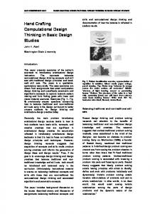
We use the state-based approach to specify the team’s actual behavior. The statechart model includes three classes: the team leader, the team member and the team. We demonstrate the approach using two team members. However, the model can be easily extended to handle any number thereof. The behavior of the team leader is specified by a statechart with two orthogonal components (i.e., concurrent substatecharts); see Figure 1. The Action and Speed components specify the team leader’s current action (e.g., running, working) and current speed (normal, fast, intensive), respectively. The statechart of a team member is similar, but has an additional behavioral element: a team member rests when a fast action is taken. To add this behavior, a superstate was added to a team member’s Action sub-statechart, specifying whether the member is in a resting state or an acting state. Each member moves into resting state after a predefined time and returns to its pre-resting state after predefined time. The exercising and resting intervals varies among the members to simulate differences in fitness conditions.
A TEAM TRAINING GAME-MODEL
To demonstrate our approach, we chose a representative game-model of a team in training, which employs the aforementioned tools. Prerecorded clips and interactive illustration of the model can be seen in http://research.microsoft. com/~yakis/gameModel/.
3.1
team leader performs various actions at different speeds, and the team members follow suit, after a short “comprehension” delay. Team members, however, are not as fit as the team leader, and need to rest while performing certain fast actions. In addition, the team leader reacts to environmental changes; when a Storm, a Flood, or a Volcano eruption occurs, the team leader performs an appropriate set of actions to handle the situation. Three cameras cover the training scene. The main one is focused on the team leader, and each of the other two covers a team member. The user instructs the team to perform an action or assigns it a training task. He or she controls the cameras’ activity and may query the running simulation.
Elements of the Game-Model
The game-model describes gym training sessions for a team of three: a team leader and two team members. The
Figure 1: The team leader’s statechart.
3.3
Training Tasks in LSCs
We used the scenario-based approach to specify training tasks for the team. The LSC model specifies several training tasks, which include a set of instructions for the team and for the environment. Four different tasks have been specified:
123
Escape, Flood, Storm and Volcano Eruption, each initiating a different scenario. Triggering a new task while another is being executed causes a violation and the new LSC terminates. An instruction message (e.g., jump, swim) triggers an LSC that forces execution of a specified set of messages. Triggering a new instruction while another is executing terminates the latter (this is done using forbidden elements). In addition, LSCs specify camera control and environmental changes. For example, assigning a flood task triggers the flood LSC, which initiates the following scenario (see Figure 2): the team participants run until the water level rises, and then swim until the water level is low enough to walk. When the flood is over, the team participants stop motion, and stand, ready for a new task. During task execution, the run instruction triggers an LSC that instructs the team to run at an increasing speed. When the swim instruction is taken, the run LSC terminates.
on the team leader. To simplify camera usage, its movement was restricted to up, down and circular. In addition, the camera can zoom in and out. Each of the team members is covered by an additional camera, which is initially disabled, and is activated by an external event (coming from the user or an external architectural component). In addition, the GUI portion of the front-end includes three panels: Action, Task and Time. Clicking a button in the Action or Task panels triggers an instruction to the team (e.g., to jump fast ) or assigns it a task (e.g., to escape), respectively. The Time panel displays the running duration of the animation.
Figure 3: Snapshots from animated front-end and the GUI.
3.5
Figure 2: The flood LSC.
3.4
The Animated Front-End
The front-end for the game-model consists of a real-time 3D animation of the training, see Figure 3. Animated renditions of a team leader and a team member were created based on the cbabe model of 3DGS [2]. The team is placed on an outdoor grass field, with some scattered houses and the team members are positioned behind the leader. Both the leader (bluish uniform and brunette hair) and the members (grayish uniforms and blond hair) can stand, walk, run, bend, crawl, swim, wade, jump and wave. Team members can also fall and rest. The user can query the model by clicking an animated figure, and the relevant data (e.g., ID, current action) is displayed next to it. Environmental changes may occur: a storm makes the sky darker, a flood displays a layer of water, and a volcano eruption changes the ground to lava. Each environmental change is accompanied by matching sound effects. The main camera is set in front of the team and is focused
Design Time Analysis
In order to visualize the scenario-based specification described in 3.3, we used the SIV tool [21]. This tool visualizes the specification as a whole, rather than each scenario independently, as can be seen in Figure 4Top, which shows the inter-dependency graph of the scenario-based specification. In the graph, each LSC is represented by a vertex, and vertices are connected by an edge if the corresponding LSCs are related. In Figure 4Top, only one type of edges are visible, namely the causal edges. These directed edges represent the option that at runtime the source LSC will drive the prechart of the target LSC towards completion; i.e., the source LSC may cause the target LSC to become active. The general structure of the specification is evident from the visualization. The specification consists of four tasks (Escape, Flood, Storm and Volcano Eruption). Some of the actions are relevant only to one task — e.g., swimming may happen only as part of the flood task — while others may take part in different tasks — e.g., walking that takes part in flood and escape, or running that takes part in all four tasks. The partitions in Figure 4Top cluster the LSCs into highly correlated groups. This results in a clear partitioning of the behavior into actions relevant to each task, and those relevant to all tasks. In Figure 4Bottom, sync edges are added. These are undirected edges representing the fact that at runtime the two LSCs may be synchronized. In this view, the most evident property of the specification is the partitioning into “input” LSCs (WO1-WO4), “task” LSCs (Task1-Task4), action LSCs (the many inter-connected LSCs in the middle), and “alert” LSCs.
124
Figure 4: The scenario-based specification as visualized by the SIV tool. Top: Causal relations (brown directed edges) clustered in communities. Bottom: Causal edges (brown directed edges) and sync edges (green undirected ones)
3.6
sage in the flood LSC instructs the environment to initiate a flood. The FloodAlert LSC is activated and notifies the front-end (arrow 5 in Figure 5). Accordingly, a water layer is displayed and a corresponding splashing sound is played. Immediately after this, the swim LSC is activated and it notifies the state-based program. The swim message enables a forbidden element in the run LSC, causing the run LSC to exit. Again, the swim LSC notifies state-based program, which in turn notifies the front-end(arrow 2 in Figure 5). The flood LSC completes after it instructs the team to walk, the environment to end the flood, and the team to stand (i.e., to stop moving). At this point, there are no more LSCs active, the statecharts are all in the standing state, and the animated figures are standing, ready for the next task. If a fast speed action is assigned to the team, each of the two team member objects will enter a resting state after some time. Consequently, the state-based program notifies the scenario-based program (arrow 6 in Figure 5) and the front-end (arrow 2 in Figure 5). Concurrently, the animated team member changes its appearance to resting, an LSC is triggered, and the team member’s camera is activated in the animation (arrow 5 in Figure 5). During a run of the system, the user may query the model or relocate the camera. When a query is requested, the front-end notifies the state-based program (arrow 1 in Figure 5), which provides the appropriate information. Changes in the camera, however, do not interact with the reactive engines.
The Game-Model at Run Time
The composed model provides a realistic simulation of the team training. The user interacts with the model through front-end, while the state-based and the scenario-based programs run in the background. Consider Figure 5 for illustration of two sample runs of the system. The first concerns a jumping action at medium speed. When the user sets the speed scroll bar to medium and clicks the jump button, the front-end notifies (i.e., sends a message to) the state-based program about the instruction (arrow 1 in Figure 5). Accordingly, the team object generates an inner event to set the statechart of the team leader to jump at medium speed (i.e., the Action sub-statechart moves to the Jumping state and the Speed sub-statechart is set to Medium). After a predefined time interval, the team object generates another event for the statecharts of each of the team members. Upon entering the Jumping state, the state-based program notifies the front-end to animate the action (arrow 2 in Figure 5). Consequently, the animated team leader jumps, and the team members follow suit. The user can change the camera’s position to view the team from different angles. Camera relocation, however, has no effect on the running simulation. As a second example, consider the flood training task specified by the flood LSC. During its execution, other LSCs (e.g., run and floodAlert) are activated, and they notify the other program and the animation. The user assigns a flood task to the team by clicking on the appropriate button. Consequently, the front-end notifies the state-based program and the flood LSC initiates the scenario (arrow 3 in Figure 5). The first message in the flood LSC is a running instruction for the team. Consequently, the run LSC is activated, and it notifies the state-based program to run at a slow speed (arrow 4 in Figure 5). Later on, a mes-
Figure 5: Message transmission between the architectural components, front-end, state-based specifications and scenario-based specifications.
4.
BIOLOGICAL MODELING
In recent years, the principles described above have guided several efforts of modeling and understanding biological systems, which are perhaps the prime example of highly complex and reactive large-scale systems. This work has resulted in several models that simulate a number of biological systems; 2D models of subsystems in the immune system, a 3D model of the development of the pancreas and reactive models for aspects in the development of the C. elegans ne-
125
matode. Below, we briefly describe two of them. The 3D model of the development of the pancreas [30], a highly important and complex system, was designed using a state-based model linked to a game engine. The former resulting from analyzed scientific data (mainly experimental results). Statecharts were chosen for this as they are suitable for describing the intra-object behavior of the biological objects themselves (e.g., cells and molecules). The model consists of numerous objects (∼10000), which at run time proliferate differentiate and migrate. At run-time the 3D animated front-end visualizes the simulation, in such a way that participating objects are represented by a 3D element and possess realistic animation attributes (Figure 6). Cells, for example, are represented by sphere-like shapes, changing in size to depict cell growth. A possible extension to the model is to add LSCs to describe inter-object scenarios, such as the impact of blood vessel growth on the organ’s development. In this work, animating the system revealed unexpected behavioral properties that emerged from the simulations at run-time. These emergent properties are not explicitly programmed, but are often a consequence of massively concurrent execution of basic elements that act in concert as a population. Another effort at biological modeling using the ideas described above involved the process of vulval precursor cell fate determination in the C. elegans nematode (see model in [26]). This project was conducted in the Play-Engine using the scenario-based approach and the LSC language. The SIV tool was applied to this model as well, and highlighted much of the high-level construct of the specification, see [21]. Many interesting features of the model were evident from the SIV visualization, such as a control LSC that triggers the execution of many other LSCs, or a clear identification of those LSCs that take part in a small process that is quite independent of the rest of the developmental process.
5.
IMPLEMENTATION
The architecture of our running example includes Rhapsody [1] and the Play-Engine [19]. These reactive engines are linked up to 3D Game Studio [2] as a three-dimensional animated front-end using a central routing server in a starlike topology. This architecture can be extended by using any number of additional components of any related kind (e.g., Matlab as done in the pancreas model [30]). In this work, we used the SIV tool in design time, however the tool itself supports run time visualization too. The model was executed on three PC dual Core4 machines running under Windows XP with 3G RAM memory. The machine running the animation carried two GForce7300 cards by nVidia employing ATI CrossFire technology.
5.1
The Central Routing Server
The central routing server was implemented as a multithreaded executable application (written in C++). Each thread of this routing server serves as a communication channel for one architectural component. A TCP socket is initialized upon registration to the server, enabling message transmission. The messages are XML documents of a general (similar to SOAP) predefined form: the header of the documents carries the source and destination, while the function to be generated is coded in the document’s body. The server analyzes the header of a received message and directs it to its final destination .
5.2
The State-Based Specification
To enable communication of state-based specifications and Rhapsody with external components through the central server, we define sets of incoming and outgoing states. An incoming state features a set of reactions that can be triggered by external events. Similarly, an event is sent from the specifications to an external component upon entering an outgoing state. The destination and the contents of such a message are encoded inside the appropriate outgoing state itself. The communication was implemented as an external library (written in C++) that extends Rhapsody to support communication and XML parsing.
5.3
The Scenario-Based Specification
To enable communication of scenario based specifications and the Play-Engine with external components through the central server, we defined specially designated sets of incoming and outgoing LSCs. A message received in the scenariobased specifications triggers an incoming LSC, which initiates a particular scenario. Likewise, a message is sent to an external component when the system execution triggers an outgoing LSC. TCP communication was implemented as a Visual Basic application as part of the model’s graphic interface.
5.4 Figure 6: Biological model of the pancreas. A. 3D animated front-end for the pancreatic development. B. The pancreatic structure emerging from the simulation. C. User interaction: a dynamic cross-section slicing. D. Mathematical analysis of model: number of cells as function of time.
The 3D Animated Front-End
The three dimensional authoring tool, 3D Game Studio (3DGS see [2], supports real-time rendering of 3D animation. The scripting language of 3DGS, C-Script, enables control of animation objects. To enable communication, the front-end contains specially designated sets of incoming and outgoing C-Script functions. The front-end sends a message upon triggering an outgoing function by the user (or an external component), and a receive message triggers an
126
incoming function that generates an animation change. This is the heart of the link between the animation and the reactive driving engines. TCP communication was implemented as an external dll, extending the C-script language to support communication and XML parsing.
5.5
Scenario Inter-dependency Visualization
The SIV tool visualizes scenario-based specifications by a force-directed layout [15] of the inter-dependency graph. The graph itself is generated by an extension of the PlayEngine tool, and is passed to the SIV tool as a graph-XML file. SIV can be executed as a stand-alone tool, with an appropriate graph-XML as an input, or it can interact with the Play-Engine to visualize the currently active Play-Engine specification. The latter allows one to select an LSC from SIV to be viewed in the Play-Engine. The SIV tool itself is written in Java, using the Prefuse toolkit (see www.prefuse. org). See detailed description of the tool in the SIV website www.wisdom.weizmann.ac.il/~itais/research/SIV/.
5.6
The Architecture at Run-Time
Each component, when executed, initiates a connection with the central routing server. The setting of components in the architecture enables pairwise message transfer between them. At run-time, message passing drives the simulation in the participating components. For example, messages from the reactive engines (i.e., Rhapsody and PlayEngine) drive the animation in the front-end. In the current implementation we addressed synchronization in a rather ad-hoc manner by specifying different clocks for each component to alert in cases of loss of synchronization. There are numerous techniques as to how to deal with time in a distributed environment, such as doing so using a centralized clock tick.
6.
RELATED WORK
Much simulation work deals with the visualization of reactive systems by adding certain effects to a reactive system formalism. These can often depict more than standard kind of GUIs, but they cannot be considered truly flexible and realistic animation. Normally, animation specifications are translated into a reactive formalism (e.g., Lotus), and the animation is carried out for the graphical reactive model itself [27]. An interesting kind of extension to this approach adds interactivity, by embedding the reactivity in the animation itself, albeit in a somewhat limited way. Real time interactivity of three dimensional figures was implemented as a hierarchical set of abstractions in the ReActor system of [6]. In later work, Elliot and Hudak defined the Fran system, in which reactivity is specified using λ-calculus based tools, and is then embedded in an animated 2D-GIF [14]. There is also a similar embedding in 3D VRML. In further work, this group adapted the approach to various control system applications; e.g., in vision and robotics and termed the result FRP. Work on ‘behavioral animation’ designs reactivity for an agent and offers the ability to simulate autonomous agents using state-machines, transition systems (HPTS) and sensor-based synthetics [11, 29, 10]. Earlier versions on behavioral animation embedded various automata for controlling animated entity behavior. Also, reactive AI has been
combined with linear animation components to form learning behavioral models [16, 7]. Finite state machines (FSMs) are among the most popular techniques used in games [31]. Statecharts are essentially extended FSMs, where the features of hierarchy and orthogonality can help deal with scalability issues by presenting a concise visual description thus allowing to overcome some of the standard difficulties of using FSMs in game design.
7.
DISCUSSION
We present how several methods and techniques can act in concert to provide a clear 3D game-model. We show how they are integrated in one model, which is visualized and analyzed at design time as well as run time. We deliberately chose to focus on an intuitive model to emphasize the principles behind our work. However, it is possible to employ these tools and ideas to model large-scale complex systems with numerous elements and interactions (as was done in biological modeling). Furthermore, this setup can be easily strengthened by adding more tools. For example, data analysis software (e.g., Matlab or Mathematica) can be integrated to provide real-time analysis of the simulation (e.g., statistics, graphs; as was done in [22]). This setup helps to disclose various potential scenarios and emergence in the model. As mentioned, these principles served to model complex biological systems with numerous objects and interactions. The massive concurrent execution of many instances of objects with identical specification disclosed new properties that were not explicitly programmed into the model [30, 13, 8]. These emergent properties arise at run time from the behavior of a population and thus are rather difficult to be predicted from the specifications themselves. Analogously, the term emergent gameplay in game design describes the creative use of a game (or film-making, see e.g., Machinima [35] ) in ways unexpected by the game designer’s original intent [24, 25, 33]. It commonly appears as complex behaviors that emerge from the interaction of simple game mechanisms. In reactive models, as well as in games, when many connections between different objects and rules are combined, the likelihood of unpredicted emergent behavior increases. Game development is a challenging software engineering process, thus the quality of the game [32] and the ability to develop it on time and on budget is crucial and should be taken into account as part of the design process. Some of the features of reactive system design have already proven themselves in other domains to be beneficial in terms of the quality of the end product. In the course of developing emergent game play, methods from other domains have been adopted. For example, neural networks and cellular automata were used in previous development of various projects (see, e.g., [34]). We believe the methods discussed here also have the potential to make an impact in game design. The game-model we present here by using modeling tools from reactive software engineering and game design, emphasizes the potential of bridging concepts and tools from both of these fields to gain innovative benefits. Bringing together these two communities can lead to a fruitful exchange of ideas and progress in reactive modeling and game design. We feel that such a collaboration can be particularly beneficial for biological modeling, which is becoming an important
127
approach for integrating the wealth of scientific knowledge and data into a coherent understanding of the function of a complex system. Incorporating efforts from both fields may contribute towards the long-term goal of biological simulators of organs and organisms [23].
8.
REFERENCES
[1] Telelogic, www.telelogic.com. [2] 3D Game Studio, www.3dgamestudio.com. [3] R. Alur and T. A. Henzinger. Reactive Modules Formal Methods in System Design: An International Journal 15:7–48, 1999. [4] C. Chaouiya. Petri net modelling of biological networks. Brief Bioinform 8:210–219, 2007. [5] L. Cardelli. Abstract Machines of Systems Biology. T. Comp. Sys. Biology 3:145–168, 2005. [6] J. E. Ball, D. T. Ling, D. Pugh, T. Skelly, A. Stankosky and D. Thiel. ReActor: A System for Real-Time Reactive Animations. In CHI ’94: Conference companion on Human factors in computing systems, pp 39–40, 1994. [7] B. Blumberg, M. Downie, Y. Ivanov, M. Berlin, M.P. Johnson and B. Tomlinson. Integrated Learning for Interactive Synthetic Characters. In SIGGRAPH ’02: Proc. 29th Computer graphics and interactive techniques, pp 417–426, 2002. [8] I. R. Cohen and D. Harel. Explaining a Complex Living System: Dynamics, Multi-scaling and Emergence. J R Soc Interface 4:175–182, 2007. [9] W. Damm and D. Harel. LSC’s : Breathing Life into Message Sequence Charts. Formal Methods in System Design 19:45-80, 2001. [10] S. Donikian. HPTS: A Behaviour Modelling Language for Autonomous Agents. In AGENTS ’01: Proc. fifth international conference on Autonomous agents, pp 401–408, 2001. [11] S. Donikian and E. Rutten. Reactivity, Concurrency, Data-flow and Hierarchical Preemption for Behavioural Animation. In Eurographics Workshop on Programming Paradigms in Graphics, pp 137–153, 1995. [12] S. Efroni, D. Harel and I. R. Cohen. Reactive Animation: Realistic Modeling of Complex Dynamic Systems. IEEE Computer, 38(1):38–47, 2005. [13] S. Efroni, D. Harel and I. R. Cohen. Emergent Dynamics of Thymocyte Development and Lineage Determination. PLoS Comput Biol, 3–13, 2007. [14] C. Elliott and P. Hudak. Functional Reactive Animation. In ICFP ’97: Proc. second ACM SIGPLAN international conference on Functional programming, pp 263–273, 1997. [15] T. M. J. Fruchterman and E. M. Reingold. Graph Drawing by Force-directed Placement. Software Practice and Experience, 21(11):1129–1164, 1991. [16] J. Funge, X. Tu and D. Terzopoulos. Cognitive Modeling: Knowledge, Reasoning and Planning for Intelligent Characters. In SIGGRAPH ’99: Proc. 26th annual conference on Computer graphics and interactive techniques, pp 29–38, 1999. [17] D. Harel. Statecharts: A Visual Formalism for Complex Systems. Sci. of Comp. Prog., 8:231–274, 1987.
[18] D. Harel and E. Gery. Executable Object Modeling with Statecharts. IEEE Computer, 30:31–42, 1997. [19] D. Harel and R. Marelly. Come, Let’s Play: Scenario-Based Programming Using LSCs and the Play-Engine. Springer-Verlag, 2003. [20] D. Harel and A. Pnueli. On the Development of Reactive Systems. In Logics and Models of Concurrent Systems, NATO ASI Series, pp 477–498, 1985. Springer-Verlag. [21] D. Harel and I. Segall. Visualizing Inter-Dependencies between Scenarios. Symp. on Soft. Vis. ACM, pp 145–153, 2008. [22] D. Harel and Y. Setty. Generic Reactive Animation: Realistic Modeling of Complex Natural Systems. In Formal Methods in Systems Biology, LNBI 5054, pp 1–16. Springer, 2008. [23] D. Harel. A Grand Challenge for Computing: Full Reactive Modeling of a Multi-Cellular Animal. Bulletin of the EATCS 81:226–235, 2003. [24] J. Juul. Half-Real : Video Games between Real Rules and Fictional Worlds.. Cambridge: MIT Press, 2005. [25] J. Juul. The Open and the Closed: Game of emergence and games of progression. In Proc. Computer Game and Digital Cultures, pp 323–329, 2002. [26] N. Kam, H. Kugler, R. Marelly, L. Appleby, J. Fisher, A. Pnueli, D. Harel, M.J. Stern and E.J.A. Hubbard. A scenario-based approach to modeling development: A prototype model of C. elegans vulval fate specification. Developmental Biology, 2008. [27] J. Magee, N. Pryce, D. Giannakopoulou and J. Kramer. Graphical Animation of Behavior Models. In ICSE ’00: Proc. 22nd international conference on Software engineering, pp 499–508, 2000. [28] A. Pnueli The Temporal Logic of Programs. Proc. 18th IEEE Symp. Found. of Comp. Sci. (FOCS77), pp 46–57, 1977. [29] H. Noser and D. Thalmann. Sensor Based Synthetic Actors in a Tennis Game Simulation. The Visual Computer, 14(4):193–205, 1998. [30] Y. Setty, I. R. Cohen, Y. Dor and D. Harel. Four-Dimensional Realistic Modeling of Pancreatic Organogenesis. Proc Natl Acad Sci U S A, to appear, 2008. [31] E. Dybsand. A Finite State Machine Class. Game Programming Gems, pp 237–248, 2000. [32] T. C. N. Graham and W. Roberts. Toward Quality-Driven Development of 3D Computer Games. Proc. 13th International Workshop on Design, Specification and Verification of Interactive Systems (DSV-IS 2006), LNCS 4323, pp 248–261, Springer-Verlag, 2007. [33] P. Sweetser. Emergence in Games. Charles River Media, Game Development Series, 2008. [34] P. Sweetser and J. Wiles. Scripting versus Emergence: Issues for Game Developers and Players in Game Environment Design. International Journal of Intelligent Games and Simulations 4:1-9, 2005. [35] P. Marino. 3D Game-Based Filmmaking: The Art of Machinima. Paraglyph, 2004. 1 Part of Itai Segall’s work was done at Microsoft Research Cambridge.
128