Nov 1, 2004 - The Software Engineering Institute defines a software architecture as the structure or ... The technical architecture definition matches well with the standard ..... fashion. Data is passed in a publish-subscribe manner. A custom Agent .... communicate through an internal blackboard using tightly-coupled, ...
Creating a Distributed Field Robot Architecture for Multiple Robots
by
Matthew T. Long
A thesis submitted in partial fulfillment of the requirements for the degree of Master of Science in Computer Science Department of Computer Science and Engineering College of Engineering University of South Florida
Major Professor: Robin Murphy, Ph.D. Kimon Valavanis, Ph.D. Larry Hall, Ph.D.
Date of Approval: November 1, 2004
Keywords: robotics, distributed systems, agents, java , jini c Copyright 2004, Matthew T. Long
Acknowledgments
Portions of this work were supported by DOE Grant DE-FG02-02ER45904 and ONR Grant N00014-03-1-0786. The author would also like to thank Robin Murphy and Kimon Valavanis for their support and encouragement; Lynne Parker for her help at Oak Ridge National Labs; and to Jennifer Carlson, Lefteris Doitsidis, Aaron Gage, Brian Minten, Andrew Nelson and Tim Slusser for their help in motivating the design and providing helpful discussions, demonstrations, comments and criticisms.
Table of Contents
List of Tables
iii
List of Figures
iv
Abstract
vi
Chapter One 1.1 1.2 1.3 1.4
1.5 1.6 1.7
Introduction Introduction to the Work Research Question Research Approach Terminology 1.4.1 What is Architecture? 1.4.2 What are Distributed Systems? 1.4.3 What are Agents? Demonstration Domain Contributions Thesis Organization
1 1 2 2 3 3 5 6 8 9 10
Chapter Two Related Work 2.1 Distributed Robotic Architectures 2.1.1 Software-Enabled Control 2.2 Software Agent Architectures 2.3 Summary
11 11 13 14 17
Chapter Three Approach 3.1 Requirements and Design Constraints 3.2 Sensor Fusion Effects– The Hybrid Precursor 3.3 Distributed Layer 3.3.1 Capabilities and Attributes 3.3.2 Module Management and Security 3.4 Tutorial:Java and Jini 3.4.1 Why Java? 3.4.2 Why Jini? 3.4.3 Concepts 3.5 Summary
18 19 20 23 23 25 26 26 27 30 36
Chapter Four Implementation 4.1 Java Implementation 4.1.1 Interface Hierarchy 4.2 Integration with Jini 4.2.1 Activation and System Initialization 4.2.2 Sharing Capabilities and Attributes 4.2.3 Authentication and Authorization
37 37 37 41 43 46 49
i
4.3
4.2.4 Fault Tolerance and Recovering from Service Failure Summary
50 50
Chapter Five 5.1 5.2 5.3 5.4 5.5
Demonstration Robot Hardware Implementing a Basic GPS Service Implementing a Waypoint-Following Behavior Using MATLAB Distributed Agents for Affective Recruitment Summary
51 52 52 57 60 64
Chapter Six
Discussion
65
Chapter Seven Summary and Future Work 7.1 Future Work
67 69
References
71
ii
List of Tables
Table 1.
Reactive Components in Sensor Fusion Effects
21
Table 2.
Deliberative Components in Sensor Fusion Effects
22
Table 3.
Key Issues Relating to Distributed Computing Architectures
29
iii
List of Figures
Figure 1.
The Target Mission Scenario
9
Figure 2.
A Portion of the Original SFX Architecture
22
Figure 3.
Extending the Original Architecture by Adding a Distributed Persona
24
Figure 4.
Expression of the Persona as Capabilities
25
Figure 5.
Distributed Resource Protection
25
Figure 6.
Interacting with a Service Through a Proxy
31
Figure 7.
Operation of a Client or Service Discovering a Lookup Service
32
Figure 8.
Multicast Versus Unicast Communication
32
Figure 9.
Polling Versus Remote Events
34
Figure 10. Overview of Java Authentication and Authorization Service
35
Figure 11. The Java Platform and Some Useful Libraries and Packages
38
Figure 12. The Core Interface Hierarchy for the Architecture
38
Figure 13. Class and Interface Hierarchy for the Module-Related System Component
42
Figure 14. Initial Bootstrap Process for Service Activation
44
Figure 15. Server Activation in the Activation System
45
Figure 16. ATRV-Jr Hardware
52
Figure 17. UML Diagram for the Class and Interface Hierarchy Defined for the GPS Service
53
Figure 18. Event Flow for Initialization and Activation
55
Figure 19. Event Flow for Event-Based GPS Readings
56
Figure 20. Control-Theoretic GoToWaypoint as Implemented in MATLAB
57
Figure 21. DFRA -MATLAB Integration UML Diagram
58
Figure 22. User Interface for Selecting Robot Search Areas
60
Figure 23. Two Robot Passing Each Other While Performing a Raster Scan
61
iv
Figure 24. The Path of the Two Robots Performing a Raster Scan
61
Figure 25. Overall Recruitment Protocol
63
Figure 26. Schema-Based GoToWaypoint Behavioral Design
69
v
Creating a Distributed Field Robot Architecture for Multiple Robots Matthew T. Long ABSTRACT
This thesis describes the design and implementation of a distributed robot architecture, Distributed Field Robot Architecture. The approach taken in this thesis is threefold. First, the distributed architecture builds on existing hybrid deliberative/reactive architectures used for individual robots rather than creating a distributed architecture that requires re-engineering of existing robots. Second, the distributed layer of the architecture incorporates concepts from artificial intelligence and software agents. Third, the architecture is designed around Suns Jini middleware layer, rather than creating a middleware layer from scratch or attempting to adapt a software agent architecture. This thesis makes three primary contributions, both theoretical and practical, to intelligent robotics. First, the thesis defines key characteristics of a distributed robot architecture. Second, this thesis describes, implements, and validates a distributed robot architecture. Third, the implementation with a team of mobile ground robots interacting with an external software “mission controller” agent in a complex, outdoor task is itself a contribution. The architecture is validated with three existence proofs. First, an example is presented to show the implementation of a basic sensor service. Second, a basic behavior is presented to validate the reactive portion of the architecture. Finally, an intelligent agent is presented to validate the deliberative layer of the architecture and describe the integration with the distributed layer.
vi
Chapter One Introduction
1.1
Introduction to the Work
The aim of this thesis is to extend a hybrid deliberative-reactive robot architecture into a distributed robot architecture. The work is related not only to the field of robotics, but also to distributed computing and agent architectures. This chapter poses the research question, and will provide the reader with an introduction to the terminology to be used in this thesis, along with a discussion of the motivation for and the issues to be addressed by this work. This chapter will also introduce the contributions made to the state of distributed robotic research and will provide an outline for the support of these claims in the remainder of this work. The motivation for this work is the proliferation of heterogeneous mobile robots and the lack of a common, distributed computing architecture to take advantage of these robots in a way that builds on the state of the art in robotics. Currently, many robot manufacturers sell robot systems, but each system typically has a specific layer of control software with limited or no interoperability with the software of another vendor. For example, the iRobot Corporation develops robots that use Mobility software [33] and robots produced by ActivMedia Robotics run the Aria system [1]. As is discussed in Chapter Two, there are many single-system robot architectures that will run on these bases but few that are inherently distributed. In addition, while there are a number of robotic architectures that incorporate communication and can operate over multiple robots, there are few that do this in a systematic manner. An example of a domain where a heterogeneous team of robots is needed and where current architectures are insufficient is beach demining. In this domain a team of robots explores a beach for mines, finding a clear path for other vehicles or personnel to safely land and progress inland. The domain is complex, requiring systematic distributed control of a team of robots, but also requiring the capability to communicate within the team and with operators at a mission control station. This lack of a common, distributed robotics architecture for such complex tasks is addressed by this thesis. To create such an architecture, it is important to build on prior work. The scope and complexity of both conventional robot architectures and of distributed system and software agent architectures are such 1
that it would be a Herculean effort to attempt to recreate efforts that have been done, and done well. Therefore the approach taken in this work has been to take the best from these areas, and to integrate them, with modifications, into a cohesive, useful distributed robot architecture.
1.2
Research Question
The research question that this thesis addresses is thus: How do we extend a hybrid deliberative-reactive robot architecture into a general-purpose distributed robot architecture? There are several questions that should be answered as part of this question: • What are the desirable characteristics of a distributed robot architecture? • What are key components to merge from existing distributed robot and agent architectures? • What are the missing components that must be developed?
1.3
Research Approach
The approach taken in this thesis is threefold. First, the distributed architecture builds on existing hybrid deliberative/reactive architectures used for individual robots rather than creating a distributed architecture that requires re-engineering of existing robots. The majority of intelligent ground robots are programmed using the hybrid architectural paradigm, which divides the architecture into a reactive or behavioral layer and a “higher” deliberative layer [46]. Intelligent aerial vehicles also employ hierarchical layers of control [31]. This thesis proposes and implements a distributed layer that serves as a yet higher layer. This is consistent with the software engineering principles of modularity, information hiding, and security. It also means that the robots can function on their own even if the distributed layer has a software failure. Another advantage of the distributed layer is that it is expected to be applicable to any single-robot architecture. Second, the distributed layer of the architecture incorporates concepts from artificial intelligence and software agents. The distributed layer is loosely based on the persona concept from psychology. Each person has a persona, or way he or she interacts with the world, under different circumstances. The persona provides a metaphor for thinking about the robot and how it interacts with other robots and intelligent agents. The persona concept is also consistent with good software engineering, especially information hiding and security, since it implies that all agents do not have access to all aspects of each robot. The 2
architecture allows the development of distributed algorithms and decision making as well as interface agents and agent-oriented communication from software agency and distributed systems, allowing the architecture to benefit from advances in those domains and to ensure that the robots will be able to work with software and cognitive agents in the larger informational system. It also permits the future addition of affective computing constructs which is an emerging concept in distributed systems in artificial intelligence (see Breazeal [14] and Picard [55]). Third, the architecture is designed around Suns Jini middleware layer, rather than creating a middleware layer from scratch or attempting to adapt a software agent architecture such as Control of Agent-Based Systems. This was done for the following five reasons: • Creating a robust, functional middleware layer is a complex, time-consuming process and not the main goal of this work. • Jini is a commercially developed, stable, open product. • Jini has a thriving user community that has a vested interest in seeing bugs found and fixed. • Jini is well suited to the security, networking and event models of the Java language. • Other systems, such as CoABS, are built on Jini. This shows that Jini is a relevant and functional base for this work.
1.4
Terminology
There are several key concepts that are important to define now. This discussion should help focus the following literature survey on systems that are relevant – systems that are both distributed and agent-based or agent-supporting. In addition, this work describes an architecture, so it will be useful to define this term as well. Brugali and Fayad [17] have a good overview of distributed computing in robotics and automation; the discussion in this thesis is similar in many ways, but explores robotic and agent architectures in more depth.
1.4.1
What is Architecture?
The Software Engineering Institute defines a software architecture as the structure or structures of a software system. These structures are software elements, their externally visible interfaces and the relationships among the elements in the system [5]. Most importantly, software architecture deals with an abstraction of a
3
system, defining how elements interact within this abstraction, but not how individual elements are implemented. Levis [8, 66, 39], in work on Command, Control, Communications, Computer, Intelligence, Surveillance, and Reconnaissance (C4ISR) [29] architecture also views architecture as a “set of abstract views or models” of the system under consideration: An architecture is defined as the structure of components, their relationships, and the principles and guidelines governing their design and evolution over time. The C4ISR architecture decomposes into three areas: technical, operational, and systems architecture. The technical architecture is the minimal set of rules that define the interaction of the various elements in a system, such that the elements obey the constraints set in the operational and systems architectures. An operational architecture defines the information flow among “force elements” in a system, including frequency of and tasks supported by the information. The system architecture defines the high level composition of various elements in the system-of-systems. The architecture presented in this thesis is a technical architecture in this sense. The technical architecture definition matches well with the standard software engineering definition, so the SEI definition will be used for this thesis. Interactions among and between robots and other elements in a larger domain, such as the task described in Section 1.5, are defined by a system architecture. architecture A software architecture is the structure or structures of a system. These structures are software elements, their externally visible interfaces and the relationships among the elements in the system. Software architecture deals with an abstraction of a system, defining how elements interact within this abstraction, but not how individual elements are implemented. Middleware frameworks [7] are abstractions of a distributed computing environment. These frameworks allow software developers to more easily extend system infrastructures into a distributed environment. This is because the middleware is “in the middle”, between the operating system or network services and the application layer, abstracting the details of the system-specific networking and other low-level code. Jini is an example of a middleware framework [4]. The use of a standard middleware layer such as Jini has a benefit – systems built on top of the middleware layer automatically inherit the attributes of a distributed system.
4
1.4.2
What are Distributed Systems?
Tanenbaum [61] presents a standard definition of a distributed system: A distributed system is a collection of independent computers that appear to the users of the system as a single computer. Under this definition the important interaction is between the user and the system as a whole, not with the system’s individual elements. Also implicit in this definition is the notion that there are several discrete elements, the combination of which are the distributed system. Mobile robot platforms are almost always separate entities with independent control on discrete physical manifestations. Several questions some to mind. Does a distributed system need to have multiple computer systems to be considered distributed? Would a system that starts with three entities, but two of them fail still be considered distributed? How about if only one started initially? The biggest weakness of the standard definition is that classification can be made based on the current state of the system, rather than on the system potential. However, there are other distributed system definitions that apply. Waldo, et al. [67] use the term distributed computing to refer to programs that make calls to other address spaces, possibly on another machine. This view resolves the questions raised above: as long as the system has the potential to be distributed, the the system is considered to be distributed. The robotic system under development is a distributed system in the sense that it can support multiple robots that have the same goal and appear as a single system. Yet each robot is a collection of communicating and cooperating programs, and is also distributed on a finer scale. Under the concept of distributed potential, it is irrelevant whether there is one robot or a hundred – the team size axis is orthogonal to the distributed axis since each robotic agent is distributed by itself. distributed robot system A distributed robot system is a collection of robot systems where each robot in the system has components that can access the address space of other components, whether the component is on the same robot or another. This suggests a related definition: multi-robot system A multi-robot system is a collection of robots that have components that may or may not be able to access the address space of other components. An example of this is “swarm” robots. 5
Under these definitions, all distributed robot systems are multi-robot systems, but multi-robot systems are not necessarily distributed. More terminology related to the specific distributed system middleware used in this work will be introduced in Section 3.4.3. It is important to note that this work is primarily concerned with distributed robot systems. While this does intersect the domain of multi-robot systems, it is more concerned with providing a framework that supports distributed programming on mobile robots.
1.4.3
What are Agents?
Bradshaw [12] notes that the term agent has different definitions to different people. He breaks the definitions into two categories: aspiration and description. • Aspiration: A software agent can act on behalf of someone to carry out a particular task which has been delegated to it. Agents can infer intent from directions and can take into account the peculiarities of the user and the situation. An agent is not defined by a set of attributes, but rather by someone attributing agent-hood to it. • Description: An agent is a “software entity which functions continuously and autonomously in a particular environment, often inhabited by other agents and processes.” This definition is attribute based – an agent might possess attributes like the following: reactivity, autonomy, collaborative behavior, “knowledge-level” communication ability, inferential capability, temporal continuity, personality, adaptivity, and mobility. The descriptive definition of an agent is the more meaningful of the two. The aspiration definition is particularly fuzzy, since two observers of the same system may disagree on the “agent-hood” of the system. A descriptive definition also allows the use of a metric to determine whether a particular software component is an agent or not. But does this definition hold for robotic agents? A definition adapted from Murphy [46] expresses the robotics communities’ definition of an agent: “An agent is a self-contained, independent and self-aware module that can interact with the world to make changes or to sense what is happening.” There is one problem with this definition: What does self-aware mean? Is any robot or software agent truly self aware? This definition is broader than Bradshaw’s, in that the definition is not limited to a software entity, and can include physically situated hardware/software systems such as robots.
6
A comprehensive definition from Wooldridge [72]: “An agent is a computer system that is situated in some environment, and that is capable of autonomous action in this environment in order to meet its design objectives.” An extension to this for intelligent agents: “an intelligent agent is one that is capable of flexible autonomous action in order to meet its design objectives”. In this context, flexibility means three things: reactivity, pro-activeness and social ability. For intelligent agents, reactivity means the ability to perceive their environment and to respond to changes. Pro-activeness simply means to exhibit some form of goal-directed behavior. In other words, the agent is not merely reacting to the environment, but has a reason for acting. Finally, an agent’s social ability is defined as the ability to interact in a meaningful way with other agents in the environment. Since agents can be classified further by denoting the environment in which they operate and the degree to which they are situated, it is important to verify that this definition can support the full spectrum of agency. Under this definition a robot as a whole can be considered an agent. In this case, the environment is the physical world, inhabited by other agents. The robotic agent as an entity can interact with other agents to pursue its tasks. The robot may also contain agents of a finer granularity. These agents are software agents that are responsible for the internal functions of the robot. Their environment is the computing environment on the robot itself, and possibly other robots if communication allows. While some of these agents can be mobile, many are situated software agents responsible for the management and execution of certain resources local to a particular robot, such as sensors or effectors. While many services on a robot can be agents, many are simply active objects. An active object is an object that has its own thread of control. This thread of control means that active objects are somewhat autonomous, able to exhibit some behavior without being operated on by another object. Passive objects only exhibit behavior when acted on by another object. Even though active objects are somewhat autonomous they are not intelligent agents. An example of this could be a drive effector service that passes motor commands to a motor. The service might autonomously maintain closed-loop control of the motor, but may not be able to interact with the rest of the system in an intelligent manner. This distinction is important in classifying distributed systems. Cognitive agents such as humans or animals do not fit this agent definition, however, as it deals solely with computer systems. Since cognitive agents will be acting in the environment – either directly with the robot in the physical world or with the robot’s control software – the definition must be modified to include them as well. For the purpose of this thesis, the following definitions of agent will be used:
7
agent An agent is something or someone that is situated in some environment, and that is capable of autonomous action in this environment. intelligent agent As above, an intelligent agent is an agent that is capable of flexible autonomous action. Under this definition, a software agent is an agent that operates in a purely software world. A software agent’s percepts are related to software and any action this agent may take operates on software. In a similar vein, physical agents are situated in the physical world and receive percepts from the world and take action in this world. In this thesis, a robot is considered a physical agent, while portions of the control software may be software agents if sufficiently complex. Physical or software agents may or may not be intelligent agents, but cognitive agents are always intelligent agents, with cognition denoting a particularly strong form of intelligence.
1.5
Demonstration Domain
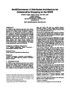
This section describes the target mission scenario, a cooperative mine detection task, shown in Figure 1. In this example, two ground robots and an aerial robot are performing a mission in an outdoor environment, searching for mines in a region. One ground robot is performing a raster search of an area, while the other is assisting the Vertical Take-Off and Landing with identification of a potential target. Two examples of work using this architecture supporting this domain are described in Section 5.3 (a waypoint-following behavior) and Section 5.4 (recruitment of robots to help with a task). Each robot has an associated Operator Control Unit (OCU), which is the direct control unit used by the robot operator. The robot operator can send supervisory commands to the associated robot and interrupt the robot’s operation if needed. A Ground Control Station is also located nearby. The GCS houses a set of Ground Control Unit s. This is the control unit used by the “payload specialist” or robot mission human expert. The GCU unit may also serve as an OCU. Finally, supervising the entire operation is the Mission Control Unit. The MCU may also serve as a GCU or OCU. This figure also shows some of the communication possibilities, denoted by the lines connecting the actors in the scenario. The outdoor environment is constantly changing, and this affects the connectivity of the elements in the field. The overall system must be able to adapt to the changing communication environment.
8
Figure 1. The Target Mission Scenario 1.6
Contributions
This thesis makes three primary contributions to intelligent robotics. These contributions are both theoretical and practical. First, the thesis defines the characteristics of a distributed robot architecture for teams of heterogeneous mobile robots based on field experience. There are seven key requirements: • Support for both behavior-based and deliberative robotic paradigms. • The architecture should use open standard and / or open source for compatibility and correctness. • The architecture should be fault tolerant at both the system and component levels. • Adaptability in the face of changing operating conditions is critical. • The ability to modify, administer, log and maintain the system at runtime is needed for a long-lived system. • A consistent programming model is useful to abstract the locality of objects in the system. • The system should be designed to be dynamic from the start to avoid arbitrary restrictions. This is a major contribution to the theory of robot architectures because it helps shape what they are to do. It is also a contribution to the implementation of robots because it provides initial design criteria. Second, this thesis describes, implements, and validates a distributed robot architecture which: 9
• is consistent with good software engineering principles • can be applied to any existing single-robot architecture • is consistent and compatible with agent architectures, making it extensible for emerging AI concepts such as affective computing The robot architecture itself is a theoretical and practical contribution. As an architecture, it forwards the theory of intelligent robotics. Because it is designed and implemented with good software engineering principles that can be ported to existing robots, the thesis reflects a practical advancement of robotics. Third, the implementation with a team of mobile ground robots interacting with an external software “mission controller” agent in a complex, outdoor task is itself a contribution. Traditionally, most distributed robot architectures have been tested in an indoor, controlled environment. This architecture has been tested in an outdoor environment, and the target domain is complex.
1.7
Thesis Organization
Chapter Two discusses work related to this thesis. Chapter Three examines the approach taken in developing this architecture. It also provides background information on the technologies that underly this solution – Java, Jini and the Sensor Fusion Effects (SFX) hybrid deliberative-reactive architecture. Chapter Four examines some of the implementation details of the Distributed Field Robot Architecture. Chapter Five lists and explains the validation of the architecture and provides several case studies of sample uses for the DFRA. Discussion of lessons learned are provided in Chapter Six. Finally Chapter Seven explores topics that remain open as future work.
10
Chapter Two Related Work For this thesis, related work falls into two primary categories: distributed robotic architectures and software agent architectures. There are a number of important considerations when developing a general-purpose architecture that have been generated as a result of field work [18, 20, 45, 19, 23]. The architecture must support both behavior-based and deliberative robotic paradigms. The architecture should use open standards if possible. This allows greater flexibility in choice of design, development and analysis and aids in future maintainability. The system should be reliable in the face of hardware faults, software errors, and in the case of a distributed system, network errors. For a long-lived system, the ability to be modified, administered, logged and maintained at runtime is important to keep a high quality of service for the system. The architecture should enable adaptation and flexibility in the face of dynamically changing operating environment and conditions. Having these characteristics will allow a system to have a greater availability and the potential for usefulness in circumstances other than for which it was programmed. Finally, the system should treat both local and remote references in a consistent, systematic manner for ease of design and implementation. These will be the primary metrics considered when examining relevant literature.
2.1
Distributed Robotic Architectures
There are large numbers of single-system robot architectures. Examples include Murphy’s SFX [47], Brooks’ subsumption [16], Bonasso’s 3T [9] and Arkin’s AuRA [3]. These and other architectures have been discussed in detail in survey papers [42] and books [46, 2]. One key feature of these architectures is that they were initially designed for single-robot systems. As Parker notes in [52, 51] that while there have been numerous advances in multi-agent robotics, these have been primarily focused on providing a specific capability to a robot team. Typically, this involves adding a distributed or multi-agent capability to an existing architecture. For example, Matari´c used the subsumption architecture to examine social rules in multi-robot systems [43], as have Matari´c, Sukhatme and Østergaard [44] for distributed task planning in
11
both a real and simulated “emergency handling domain” and Parker utilized the ALLIANCE architecture [50] to explore distributed fault tolerance using a hazardous waste cleanup scenario. Gerkey, et. al. at the University of Southern California have developed Player[25], a distributed robotics architecture. The Player architecture is based around a multi-threaded socket server that supports extremely simple data communication. Clients receive data from the server on a regular interval. Player uses the UNIX file abstraction to communicate with sensors and actuators – open/read/write/close/ioctl. This device abstraction has been described more recently by Vaughan, Gerkey and Howard in [65]. This abstraction is extremely simple and powerful, but pushes a large programming burden and knowledge to the client. It is unclear what the relative usage of Player and its associated simulator Stage is, although it has been used for simulation and evaluation purposes [53]. Player is open source, released to the community for public use, but is limited in the area of runtime modification – this architecture does not support or implement many of the basic middleware functions, such as automatic service discovery. Werger [68] describes a language and architecture, Ayllu, for behavior-based control over IP networks. The foundation for this architecture is a variant of the subsumption architecture called the Port-Arbitrated Behavior paradigm. In this architecture, behaviors have externally-accessible elements called ports. Source ports can be connected to destination ports through suppressive, inhibitory, or overriding connections. The claim is that the lack of a distributed architecture such as Ayllu is the reason that behavior-based systems are problematic with regard to scaling. This architecture does not address higher level concepts that are found in hybrid architectures, such as a managerial layer – concepts that are fundamental to the architecture presented in this thesis. As in Player, it is difficult to scale the system to handle changing numbers of robots or arbitrarily add new behaviors. Ayllu was demonstrated to enable a team of three ActivMedia Pioneer 2DX robots to cooperatively track multiple unspecified moving targets in[69]. Simmons, et al. [58, 27] have developed a layered, distributed architecture that provides flexibility in synchronization granularity and attempts to integrate the strengths of both distributed and centralized coordination approaches. The architecture is composed of three layers: behavioral layer for control, executive layer for task execution, and the planning layer for high-level planning. All three layers on one robot can interact with the corresponding layers on another robot. This architecture is based on the Skill Manager of Bonasso, et al. [9], where skills are connected via input/output ports and operate in a data-flow fashion. Data is passed in a publish-subscribe manner. A custom Agent Capability Server (ACS) has been implemented to automatically disseminate information about the capabilities of individual agents. This ACS 12
is similar to the middle agent in Sycara, et al. [62]. This architecture does not leverage existing work in this domain – the ACS is an entity that is a common component of several standard middleware systems – the broker / trading service in Common Object Request Broker Architecture or the registration / lookup system in Jini. This system has been used for distributed, coordinated mapping of an empty hospital building with two Pioneer AT robots from RWI and an Urbie robot from IS Robotics[57]. Woo, et al. [71] describe a CORBA-based approach to a three-tier robot architecture. The application layer defines a set of robot services, such as image or speech processing, planning or a robot application. The middleware is responsible for the service broker and trading service. A weakness of this work is that the application layer is not well defined. It is unclear whether there is any underlying robot architecture. The work seems to model the entire robot as a single service. This approach can work for applications that have a small and well-defined set of capabilities and requirements, but it is unclear that the system will scale well. For validation, the architecture was demonstrated on LEGO Mindstorm, Khepera and B21r robots, with a sample Java interface to remotely operate the robots.
2.1.1
Software-Enabled Control
The Defense Advanced Research Projects Agency Software-Enabled Control (Software-Enabled Control) program is aimed at improving the control systems for autonomous aerial vehicles. While the work of the SEC community uses a standard distributed middleware layer little has been said about the application to multiple Unmanned Aerial Vehicle s – the implication being that current systems are limited to a single UAV. But because CORBA is being used, there is no compelling reason why distributed components of the system are unable to be used as part of a larger distributed system – this approach is an example of work that is distributed because it is built on top of a middleware layer that is itself fundamentally distributed. Finally, this work is relevant because it shows that the overhead for a middleware-based distributed system is low enough that it can be used for closed-loop control on a single system. This is an important validation for the work in this thesis. In [30] and [31], Heck, et al. provide a summary and detailed description of software enabled control. SEC is motivated by the advances in software technology and aims to increase the capability of digital control systems. SEC has a reliance on distributed computing – spreading the burden of computation around to enable robust operation. The papers discuss several portable middleware solutions: CORBA, Java RMI, and Jini. It also discusses several interaction models: point-to-point, client-server and publish-subscribe. Real-time requirements can also pose problems, especially in a distributed domain. SEC 13
also takes advantage of a software architecture to allow pluggable components. Finally, the papers discuss using MATLAB as a low-level control, with the middleware “glue” to make the components work together. Schrage [56] notes a problem with current UAV controllers is that they are not sufficiently robust to support complex flight maneuvers. The solution is the use of a multi-layer control architecture. The highest layer supports the mission planning and situation awareness. The lowest layer is the actual flight control. The mid layer deals with mode switching and transitions. This mid layer is called the Open Control Platform, and uses Real-Time CORBA middleware to interface the UAV dynamics, controllers, sensors and actuators. The open control platform was demonstrated on a Yamaha R-50/RMAX helicopter [70]. Paunicka, Corman and Mendel [54] describe another CORBA-based middleware and software architecture. There are several interesting aspects to this work. The first is the discussion of certain optimizations that aided in high performance. One is the use of a shared memory as opposed to ethernet to achieve low latency in data requests. Also, the use of thread specific storage minimized the ORB overhead during message calls. Finally, the CORBA system allowed for light weight events, client-side caching and support for hardware timers at the application level. The architecture used a Controls API which is essentially an abstraction layer so the engineers designing the control system would not need to interact with the system. This API uses an XML description and a simple programming interface. The Extensible Markup Language describes 1) worst-case execution time, 2) allowable rates of execution 3) scheduling type 4) physical layout and 5) data types. Two lessons noted by the authors are appropriate to this thesis: 1) Software designers need to be able to treat the system at the appropriate level of abstraction and 2) Control designers don’t want to become software architects. As the architecture used is the open control platform, results from this paper should apply to work cited previously, however no specific examples were noted in the paper.
2.2
Software Agent Architectures
Since software modules that operate in the distributed layer of SFX have the attributes of intelligent agents, such as the recruitment agent described in Section 5.4, it is worthwhile to examine the literature related to software agents and determine the capabilities and constraints of agent-based architectures. The architecture presented in this thesis is a hybrid distributed/deliberative/reactive architecture that is composed of multiple, independent modules of varying complexity. Low-complexity modules, such as sensors, effectors or the other building blocks of a reactive system, are not agents. Instead they have more in common with active objects. At the other end of the spectrum, the modules with a higher complexity, such as those found in the 14
managerial layer, start to look more like agents – perhaps even intelligent agents. These modules have knowledge of the current state of the robot or other robots and the mission to which the robot is assigned. Based on this information, these modules can react to the changing state of the robot, exhibit goal-directed behavior, or interact with similar modules on other robots. In short, they have the characteristics of agents. There are several programs that have funded several large research projects in agent-based systems. Control of Agent-Based Systems (CoABS) [26] is a DARPA project focused on agent-based computing, with the goal of providing semantic interoperability between heterogeneous systems without enforcing a particular standard. The agent architecture used by the CoABS project is the CoABS Grid [35]. The CoABS Grid is middleware built on top of Jini middleware, and uses three important concepts which are incorporated into this thesis: the Jini concept of a service which is used to represent an agent; the Jini lookup service, which is used to register and discover agents and other services; and Jini entries, which are used to advertise an agent’s capabilities. The CoABS Grid middleware provides a number of services specifically for an agent environment. These include messaging, logging and registration services that are tailored to the grid system. The CoABS Grid is relevant to this work because it is an agent architecture that is based on the same underlying foundation. Thus many of the lessons learned from the CoABS project are relevant to this work. As part of the CoABS project, Kahn and Cicalese [36] describe several experiments with scalability on the grid. The experiments discussed in this paper investigate how timing of sequential agent registration and lookup varies as the total number of registered agents increases. No degradation in performance was observed in experiments with up to 10,000 agents for lookup. Minimal degradation in registration time was observed as the number of registered agents increased. This is important, since the underlying middleware, Jini, is the same middleware that is used in this thesis. UltraLog [22] is a DARPA project aimed at creating survivable large-scale agent systems. The domain for the project is operational logistics, with an ultimate goal of a system of over 1000 agents operating in an adversarial environment. The goal is to operate with up to 45% information infrastructure loss with not more that 20% capabilities degradation and not more than 30% performance degradation. The system will run for 180 days, representing a major sustained military operation. The agent base underneath UltraLog is the Cognitive Agent Architecture (Cougaar) [6]. Cougaar is a component-based, distributed agent architecture, with communication handled by a built-in asynchronous message passing protocol. Cougaar supports a two-tier communication model: agent-agent and plugin-plugin. Agents communicate with each other as peers, in a loosely-coupled, asynchronous manner. Plugins (agent components) 15
communicate through an internal blackboard using tightly-coupled, transactionally-protected interactions. This architecure is relevant to this thesis because of the dynamic environment in which a robot system operates. There is little difference to a system that must recover from a loss of service due to deliberate network sabotage and a system that must recover from a loss of service due to a robot losing connectivity to a network. Brinn and Greaves [15] describe efforts funded by the DARPA UltraLog project to investigate the survivability of agents under harsh conditions. A working definition of survivability of a system is the extent to which the quality of service of a function is maintained under stress. Stress typically falls into the categories of information attacks, loss of processing resources and increased workload. The paper suggests three general categories of agent properties: absolute (property may never be violated), binary (property may be present or not present, but should be present as much as possible) and partial (may be wholly, partially, or not at all present, but should be as much available as possible). Defense strategies against attacks consist of the following: anonymity, public Application Programming Interface, mobility, dynamic capability discovery, autonomy, task orientation and composability. The methodology used to aid in agent survivability: prevent attacks if possible, detect attacks that occur, contain the damage caused by an attack and recover after the attack is over. The big claim of the work is that a distributed multi-agent system built using the methodology of deployed defenses supports survivability against a given threat to a predictable degree. The defense strategies and methodology noted here are relevant to the design of this system (Chapter Three). Helsinger, et al. [32] describes a performance measurement system built into the Cougaar agent architecture. Performance measurement is difficult for several reasons: sheer volume of data from a large number of agents, data retrieval must often be synchronized in a central repository for analysis, measurements can often impact performance, and needs and priorities for measurement can often change over time. The consumer of the data is important – whether it is for internal or external assessment. This distinction impacts the type of data recorded. The use the data is put to is also a factor – is it for trend analysis, state change notification, or general state information. Is the collecting of the metrics separate from the usual agent communication channel? The collection method can impact the type and speed of data collection. Finally, what level of abstraction is collected? System-level metrics have different reporting levels than agent-level metrics which are different than application-level metrics. Cougaar uses a system with three facets: many data streams at multiple levels of system architecture, several different distribution channels with different quality levels, and dynamic selection / change as the system changes. 16
Bradshaw, et al. [10, 13, 11] discusses the Knowledgeable Agent-oriented System (Knowledgeable Agent-oriented System), an agent architecture that is geared towards policy-based agent management. Policies that are set can control various aspects of the agent system, from how agents can communicate to allowing, denying or obligating certain actions. This is accomplished though the use of a guard. The guard can interpret policies that the domain manager has approved and can enforce them with appropriate native mechanisms. These concepts are critical to an adaptive and flexible deliberative layer. As the operating environment changes, policies can adapt to enable more robust behavior. For example, if network bandwidth drops, a policy might come into effect that disallows certain remote communications. Sycara’s RETSINA [62] is a multiagent system (MAS) architecture. RETSINA is an independent and reusable substratum that supports multiagent communication and social interactions. The paper claims that there is no consistent definition of what constitutes a MAS infrastructure and what functionality it should support. The paper attempts to address this in the context of technology development, applications and use, not necessarily scientific or educational endeavors. There are four basic agent types in the RETSINA functional architecture: interface agents that interact with users, task agents that help users perform tasks, information agents that mediate access to information sources, and middle agents that help match agents requesting services with agents providing services. The RETSINA architecture has been applied in several domains, such as logistics planning [38], e-commerce [63] and personal web management [21].
2.3
Summary
The works presented here fall into two categories: distributed robotic architectures and software agent architectures. While the distributed robotic architectures work well for robotics, as a whole they do not address three key characteristics that are important to this work. Most of the architectures are not built on open source or standards and thus have a limited user base. Few also incorporate distributed communication in a systematic manner – often there is a sharp distinction between local and remote communication. Finally, many are not inherently dynamic. Systems are typically constructed in an apparently ad hoc and fixed manner. Agent architectures, on the other hand, do not have these limitations. Most are built on a common middleware, often Jini or CORBA. In agent architectures support for robotics of any sort is nonexistent. Thus, the literature reviewed in this section indicates that a successful approach should draw from both fields.
17
Chapter Three Approach
This chapter describes the approach taken in the DFRA to provide distributed capabilities on top of a hybrid robot architecture. As discussed in Section 1.3, the approach taken is to extend the Sensor Fusion Effects (SFX) hybrid architecture and add a distributed layer. This distributed layer takes inspiration from the concept of a persona from psychology. It is also in this layer that many concepts from artificial intelligence and software agents play a role. Finally, the approach utilizes the Jini distributed architecture for the underlying middleware layer. The system makes use of modules to implement all of the services on the robot. The architecture also supplies high-level service managers for the coordination and functional integration of low level modular services. Modules are exported to a distributed run-time system as services with certain attributes and types. Service can then be searched for (using a distributed-object lookup service) based on functional attributes rather than details of actual implementation or physical location. This type of architecture allows a decoupling of client and server. Clients, in an abstract sense, are interested in services with particular attributes that provide or consume certain types of data. For example, processes running on one robot might need to request perceptual data from a remote source such as another robot. In this case, a service able to supply the correct type of data would be searched for using its functional attributes (type of data or location of data source, for example). If a service is found, an interface (proxy) can be provided to the requesting process in a modular fashion regardless of where the requested services physically resides or how it is implemented at the local level. This chapter is organized in the following manner. Section 3.1 enumerates the requirements and design constraints that influenced this work. Following this, Section 3.2 provides background on the hybrid deliberative/reactive robot system that is used as a foundation for the distributed extensions described in Section 3.3. Section 3.4 provides a discussion of Java and the Jini system. Finally, the chapter summary shows that the approach taken satisfies the constraints on the system.
18
3.1
Requirements and Design Constraints
There are seven key constraints that influenced the approach taken to the design of this system: • Behavior-based and deliberative support: The architecture must support both common robotic paradigms. Behavior-based control has historically worked well for low-level, time-sensitive control, while the deliberative approach is geared toward learning, artificial intelligence and processes with weaker time constraints. • Open standards: Robot hardware and software platforms do not typically have an immensely long life – several different models of robots currently used have been either discontinued by the manufacturer or the manufacturer has gone out of business. Because of this, it is important to build on a base that is open, flexible and extendable. While specific robot hardware is beyond the scope of this work, an important working requirement is that the software be built at least on open standards and on open source if possible. • Fault tolerant: Both the overall system and individual modules should be reliable in the face of hardware faults, software errors and network problems. This involves the capability for introducing advances from fault detection, identification and recovery. The architecture should be able to incorporate prior [41, 73] and future work in this area. • Adaptable: The system should also be able to adapt to its operating environment. Because the system is based on a Java foundation, portability is less of an issue as long a all services correctly implement their interfaces. Thus mobile code will be able to adapt to its operating environment. However, there is a more subtle operating environment that is as important – the network operating environment. Here modules need to adapt to preserve or extend resources to allow the system as a whole to function – to be good “network citizens”. This may involve limiting communication and message passing to maintain sufficient bandwidth for critical services to function correctly. Fortunately components of the deliberative layer such as the performance monitor and the resource managers can address this problem. While there is no current solution, the architecture must be flexible enough to allow a solution in the future. • Longevity: An ultimate goal of a system such as this is longevity. A robot should not have to be taken out of service for the installation of changes and updated. To support this, components need to be modified, administered, logged and maintained at runtime. 19
• Consistent programming model: The implementation should abstract the locality of objects. The same method should be used to access local or remote services without sacrificing error handling or performance. While this constraint is primarily of concern for implementation, it does impact the approach taken and the conceptual model of how services are located and acquired. • Dynamic system: The system should be dynamic rather than static. It should be able to flexibly accommodate new sensors, effectors, or other components. This also implies that clients will need to discover the services that are needed at runtime and adapt to the addition and removal of services over time. For a client in a distributed environment, the most important characteristics of a service are the capabilities and attributes of the service and the tasks that it can perform. This holds as well for robotics. If a robot has two identical cameras providing color images (the capabilities of the sensors), then a client will not have a preference between which camera provides an image, all else being equal. However, if the two cameras are mounted in different locations on the robot (the attributes of the sensor) then there may be differences in the client’s preference for service. Thus, a service should provide a listing of its various capabilities and attributes to clients in the distributed system, allowing a client to make an intelligent choice related to the services available in the system. Since the design constraints require adaptation to a changing environment, these capabilities and attributes must be changeable as the system evolves or services fail.
3.2
Sensor Fusion Effects– The Hybrid Precursor
SFX (SFX) is a managerial architecture by Murphy [48] designed to incorporate and enhance sensor fusion. As a managerial architecture, SFX has both deliberative and reactive components. The primary component of the reactive layer is the behavior. A behavior maps from some sensing percept generated by a perceptual schema to a template for motor output, known as a motor schema. A perceptual schema processes sensory data and other percepts to generate a representation of what is sensed. For example, a perceptual schema may process a camera image to generate a face percept representing the location of the closest face in the image. It is at this stage that sensor fusion can take place, one of the primary goals of the SFX architecture. Sensor fusion is the process of fusing sensory input from multiple sources to generate a combined percept. A color camera image and an infrared heat image can be fused to generate a more reliable face percept since the fusion step can discard portions of an image that look like faces, but do not have an associated thermal
20
image. This fusion stage can incorporate techniques from Dempster-Shafer theory or Bayesian filtering to improve results. Once a percept is generated, the behavior passes the information to a motor schema. The motor schema incorporates the control necessary to act on the percept. This may involve actions ranging from moving the robot to orienting a pan-tilt unit to achieve a better view. Appropriate construction of motor schemas can lead to action-oriented perception, with portions of the control of a robot specifically designed to attain more reliable sensing. The reactive components are shown in Table 1. While there may be considerable processing required in the generation of percepts, the data flow in this layer is straightforward in the context of behaviors: sensors to perceptual schemas to motor schemas to effectors. In this manner, behaviors can act and react to environmental stimuli, allowing the robot to operate in a timely manner. Table 1. Reactive Components in Sensor Fusion Effects Component Role Sensor A representation of a source of information about the environment. Effector A representation of a method of interaction with the environment. Perceptual schema A template for sensing. Motor schema A template for a physical activity. Behavior A template which contains a perceptual schema and a motor schema.
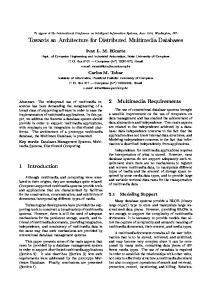
While reactive components operate rapidly, they do not have the ability to plan or to even maintain past state. Deliberative components executing at a slower pace do have this ability, however, and many are incorporated in the SFX architecture. The components in this layer fit the prior definition of agent – they can react to a changing environment, have goal-directed behavior, and can interact socially. In the original SFX, this social interaction was solely within the robot – agent to agent on the same system. The primary agent is a mission planner. This agent is responsible for mediating between the user commands and the other agents and components in the system. The three primary agents that it will interact with are resource allocation and control agents – the Task, Sensing and Effector managers. Each manager has control over its respective types of reactive components. The Sensing Manager, for example, is responsible for maintaining the best sensing state possible. Prior work done with this manager includes error handling [41, 73] and sensing allocation [24]. See Table 2 for a listing of the deliberative components and their responsibilities.
21
Table 2. Deliberative Components in Sensor Fusion Effects Component Role Task Manager An agent responsible for control of the behaviors required to complete a task. Effector Manager An agent responsible for resource control of effectors. Sensing Manager An agent responsible for resource control of sensors. Cartographer An agent that is responsible for map making and path planning. Performance Monitor An agent responsible for observing the state of the robot and its progress toward its goals. Mission Planner An agent that interacts with the human and propagates constraints to the other agents in the deliberative layer.
Task Manager Cartographer Sensing Manager
Sensor, PS Outputs
Sensor Library
Effector Manager
Behavior Instantiation
Paths and Virtual Sensing
Behavioral Library
Effector Library
sensor
abstract behavior
tactical behavior
effector
sensor
abstract behavior abstract behavior abstract behavior
tactical behavior
effector
sensor
abstract behavior
tactical behavior
effector
Figure 2. A Portion of the Original SFX Architecture
22
Figure 2 shows the cognitive model employed. A more detailed description of this architecture is provided in [48, 47, 46].
3.3
Distributed Layer
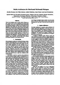
The distributed layer builds squarely on the hybrid deliberative/reactive layer described in Section 3.2. The distributed layer is formulated on the notion of a persona. In the Jungian sense, a persona is a personal facade one presents to the world [34]. In the case of a robot architecture: persona a robot’s persona is the way to represent the robot’s role, goals, capabilities and limitations to another agent. The approach taken is to extend each primary component detailed above with a portion that will interact with a distributed system. The collection of the capabilities provided by the distributed portions of each component is the robot’s persona. Figure 3 shows this visually. The figure shows the SFX foundation in Figure 2 as the base for the cognitive model, with portions of each of the relevant components extended to the distributed realm. The portions are a representation of the capabilities, attributes and knowledge of the robot – the robot persona.
3.3.1
Capabilities and Attributes
Figure 4 shows an example of the persona of a robot that has a number of capabilities exposed, such as the sensor and effector payloads and the robot’s skill set. Additionally, other information and attributes, such as a mapping or cartography capability also have a representation in the persona. These capabilities can be used by other agents in the system in an intelligent manner. A mission planner can examine the capabilities of all available robots and generate an optimal plan based on the distribution of skills. Likewise a recruitment agent such as the agent detailed in Section 5.4 can filter requests based on the match of capabilities requested and available. Or a mapping agent could request local maps from robots that have a mapping capability in their persona and stitch these local maps into a global map and return the result to the cartographers. In this manner global maps can be dynamically created and distributed by an agent that is only interested in other agents that have a particular capability.
23
Task Capabilities
Effector Capabilities
Sensing Capabilities
Information Capabilities
Distributed capability representation (persona)
Distributed resource protection Resource Protection
Security Guard
Information Protection
Task Manager Cartographer
Sensor, PS Outputs
SFX hybrid base
Sensor Library sensor
sensor
sensor
Sensing Manager Paths and Virtual Sensing
Effector Manager
Behavior Instantiation
Behavioral Library abstract behavior abstract behavior abstract behavior abstract behavior abstract behavior
tactical behavior
effector
tactical behavior
effector
tactical behavior
effector
Figure 3. Extending the Original Architecture by Adding a Distributed Persona
24
Effector Library
Task Capabilities
Effector Capabilities
Sensing Capabilities
Information Capabilities
Figure 4. Expression of the Persona as Capabilities
Resource Protection Security Guard
Information Protection
Figure 5. Distributed Resource Protection 3.3.2
Module Management and Security
Services are resources of the robot, and care must be taken to only allocate resources that can be safely allocated. In a similar vein, these resources must be protected from malicious or dangerous use. In this architecture, the persona of a robot is not protected in any way – the persona is the “public” face of the robot. However, access beyond public knowledge of capabilities may require authorization. The actual method and type of authorization is unspecified – typically most resources will use a resource manager such as the Sensing, Effector or Task managers. Optionally, services may use additional guards of some form. As is described in Chapter Seven, future work involves integrating guards from the KAoS system with the architecture to allow group-based authorizations and other domain policies.
25
3.4
Tutorial:Java and Jini
This section describes the two major technologies that this approach builds on: Java and Jini. Jini is a distributed system architecture which has a goal of providing for spontaneous networking of services – connecting any device to any other device in the network. Jini consists of a set of specifications that describe an operational model for a Jini network and how components interact within the system. The Java programming language and runtime environment serve as the foundation for this distributed system. As Java and Jini heavily influence the approach taken in this work, it is important to describe both environments and motivate why they were chosen as a foundation for this work.
3.4.1
Why Java?
Java is a strong choice as a base for an architecture that can control multiple robot platforms for five reasons: Platform-independence Java is an interpreted language that runs on a virtual machine. Since Java code is written to the abstraction of a virtual machine, then any platform is supported as long as the virtual machine will run on that platform. Strong typing Java is a strongly typed language. Because of this it is possible to associate a given class with an interface that specifies certain actions that the class must implement. With this contract is is possible to interact with objects of the class in a known manner. For instance, if a sensor module implements an interface that defines a method which returns an image to the requester, then all objects of that sensor module will honor that method as well. The use of strong typing also provides hints to the compiler as well as the runtime system. Strong typing aids in system development and with error handling during system execution [59]. Library support There are many software libraries available for Java that provide various functionality. Some of the most important for this work: 1) JDOM, an XML parser, 2) Java3D, a vector math and 3D visualization package, 3) a Java-Matlab bridge and 4) a Java-CORBA library to communicate with robot control software. Dynamic class loading Dynamic class loading is a critical benefit of the Java platform, especially in a distributed scenario. Dynamic class loading allows a Java program to load classes at runtime. This enables the use of classes that may not even have been written when the Java program was started. In a distributed environment programs or services may run for extended periods of time. Robots may 26
move around their environment and may wish to share information or code with programs on other robots. The ability to do this dynamically is vital. Performance Since Java is a byte-compiled language, it has traditionally been considered slow. Java runs through a virtual machine that interprets the bytecode stream and generates the machine instructions to perform each operation. This interpretation step reduces performance. However, modern virtual machines include a just-in-time (JIT) compiler. This compiler will compile basic blocks of Java code to machine code the first time the block is executed. Subsequent executions will use the compiled code rather than re-interpret the bytecode. While this operation is certainly slower than a pure compiled program, it is faster than a purely interpreted program, and sufficient for our purposes.
3.4.2
Why Jini?
An apocryphal quote, typically attributed to Peter Deutch, motivates why Jini is used in this work. “Essentially everyone, when they first build a distributed application, makes the following eight assumptions. All prove to be false in the long run and all cause big trouble and painful learning experiences. • The network is reliable • Latency is zero • Bandwidth is infinite • The network is secure • Topology doesn’t change • There is one administrator • Transport cost is zero • The network is homogeneous” – Attributed to Peter Deutch While the quote has evolved over time, the problems referred to still remain. These fallacies typically manifest themselves in three ways (Table 3): as programming model-related issues, as programming language-related issues, or as infrastructure-related issues. Jini is an architecture that is designed to overcome some of these issues and limitations. Using a distributed programming model leads to five severe problems (Kumaran [37]): 27
Network latency Often, a goal in creating a distributed system is to hide the network from the programmer. While this can simplify programming, it can introduce serious errors because of latencies inherent in the network – local method calls are faster than remote method calls. Instead, the designer should know whether certain method calls will incur this overhead. Partial failure Failures can occur in both local and distributed systems. In purely local systems, failure of a component typically causes a total failure of the faulty program. However, in a distributed system, failure of one component need not affect other components executing on a different system. This is known as a partial failure. However, failures of this sort are difficult to handle gracefully in a distributed environment since all that is known is that the remote component is not responding. Concurrency When multiple clients wish to access a single service, then concurrency of execution becomes an issue. Typical solutions to this problem are to either use a centralized concurrency control service or to implement a distributed concurrency negotiation algorithm [61]. Tight coupling between service and client From an implementation standpoint, service providers are often tightly coupled with clients that wish to use the service. This is typically through the requirement of shared interfaces and stub files. For example, CORBA requires the use of Interface Definition Language (IDL) files that specify the types and parameters of the service. On the client side, the client must have the stub files for the server to access its functionality. This coupling makes a dynamic network difficult. Notification to register interest Typically when a client requires a service, it will poll the service until the service is ready to be used. Lack of a notification infrastructure in most distributed architectures can lead to a client polling forever waiting for a response from a service. The programming language used can also introduce errors in the following manner: Address space For languages that contain pointers to memory, such as C or C++, the address space is an important issue. In these languages it is important to note whether the memory reference is local or remote – using a memory address from one address space in an incorrect space can lead to disastrous consequences. Most distributed systems contain some form of address mapping to help with this, but in a system with weak typing there is no guarantee that the system can catch all memory references. Finally, the network infrastructure and network environment can introduce error. Flexibility in this regard is important to retain the ability to use the appropriate protocol for the task: 28
Dependence on the request protocol There are a number of common distributed architectures in widespread use, and each architecture has its own communication protocol: Java Remote Method Protocol (JRMP) for Remote Method Invocation (RMI) and Internet Inter-Orb Protocol (IIOP) for CORBA. If a system needs to integrate components from each of these systems, more protocols are needed. For example, RMI/IIOP will allow Java to access CORBA objects on a network. While this interoperability is possible, it leads to increased complexity and the potential for error.
Table 3. Key Issues Relating to Distributed Computing Architectures Issue
CORBA
RMI Programming model No explicit distinction Explicit distinction between local and re- between local and mote objects. remote objects.
Network latency
Partial failure Concurrency
Tight coupling between service provider and requester Notification mechanism for registering interest Address space
Dependence request protocol
on
Cannot handle partial failure. Concurrency is optional.
Cannot handle partial failure. Does not handle concurrency.
Stubs need to be compiled with application.
Stub downloaded at runtime.
No distributed event notification.
Uses Java event notification model.
Programming language Exists. Depends Uses Java as a lanon implementation guage. Objects explicitly local or remote. language. Infrastructure Defines IIOP. Strong Defines JRMP. Strong dependence on IIOP. dependence on JRMP.
Jini Differentiate local and remote objects through a Java remote interface Handled through a leasing mechanism Handled through a transaction manager interface Loose coupling through dynamic class loading Uses Java event notification model.
Uses Java as a language. Objects explicitly local or remote. Protocol independent; can subsume any protocol
There are five primary benefits to Jini that are heavily used in this thesis. First, Jini provides several new protocols that enable services to dynamically adapt to the network and computing environment. Second, Jini does not specify the specific transport protocol. Instead services can use the protocol that makes the most sense for that application, be it RMI, IIOP, the new Java Extensible Remote Invocation (JERI) or a custom protocol designed for that application. Third, Jini also provides a form of naming service, called the lookup service, which allows the advertising of services and availability to potential
29
clients. Fourth, Jini also provides a distributed event system, based on the JavaBeans model. Using this, a client can register interest in a service, and can be notified when that service becomes available. Finally, Jini uses a leasing mechanism to handle partial failures. Using this mechanism, a client can obtain a lease on a service. When the lease expires, the client can either stop using the service or attempt to renew the lease. If the client or server fails, the lease will run out and the surviving process will have valuable information about the state of the failed process. 3.4.3
Concepts
There are a number of books that describe the workings of Jini in detail, for example Kumaran [37] and Li [40], and Jini has also been the subject of academic study. Vanmechelen has examined several performance characteristics of Jini and several of the underlying transport protocols [64], while Gorissen has detailed the implementation of a compact disc lookup service using Jini [28]. Some of the concepts that are presented in these works are relevant to this thesis, and key concepts are explained in this section. proxy A proxy is an object that takes the place of and represents another object. Proxies are fundamental in the distributed architecture presented here. Servers make their services available to the networked community by transmitting proxies to the lookup services. The proxy implements the service interface and is the representation of the server in the client virtual machine. All communication between the client and the server is done through this proxy (Figure 6). Proxies are classified into one of three classes: local or heavyweight proxy A local or heavyweight proxy performs all of the service’s work in the virtual machine of the client. The proxy contains the full code for the service. An example of this might be a vision processing service that passes a heavyweight proxy to the client. A division of this sort will force the client to spend its own CPU cycles to perform any processing it requires. forwarding or lightweight proxy A forwarding or lightweight proxy performs all of the service’s work in the virtual machine of the service. The proxy simply passes any messages received back to the server for processing. No work is done on the client side beyond the marshaling of method parameters and the unmarshaling of return values. A planning service might use a forwarding proxy. A service of this sort could receive all the information necessary to plan, perform the planning step, and return the plan to the client. This will use CPU cycles on the server and not on the client. 30
Machine B
Machine A client app
lookup service 1. requests service 2. supplies service proxy
service proxy
3. remote communication with service
Machine C
service
Figure 6. Interacting with a Service Through a Proxy (Adapted from [40] ) smart proxy A smart proxy is neither a purely forwarding proxy or a purely local proxy. This proxy type can handle messages in a more flexible manner. Some methods may delegate back to the service and some may perform the work in the context of the client Virtual Machine. Smart proxies are the proxy type that is used for this architecture because they allow the most flexibility. Smart proxies span the entire range from lightweight to heavyweight, so a smart proxy could forward all messages or perform all the work as needed. However, most services will likely use smart proxies with an implementation that is split between local and remote. While the framework design uses the smart proxy paradigm, the services that have been implemented thus far have not required much customization in this manner. Smart proxies have been used to cache static information about the service in the proxy, but have not yet become more complex. discovery Discovery is the process of finding resources within a networked community. Services use discovery to locate lookup services with which to register. Clients use discovery to locate lookup services which they can then query for services of interest.
31
Client or Service
multicast announcement handler
Lookup Service
1. multicast announcement
2. client connects to lookup service 3. lookup service sends registrar proxy, list of groups
unicast discovery handler
Figure 7. Operation of a Client or Service Discovering a Lookup Service (Adapted from [40] )
Multicast communication to a group
Unicast communication to a single robot
Figure 8. Multicast Versus Unicast Communication When a service wishes to discover lookup services, it can send a discovery request to a multicast address. Jini uses an address of 224.0.1.85 with port 4160. Lookup services listen to this address and will reply with a discovery response message. Lookup services are also active in this process. Each lookup service will also send a multicast announcement message to the 224.0.1.84 multicast address on port 4160. Clients can listen to this address to find lookup services, as shown in Figure 7. Both the multicast discovery request and multicast announcement message use the User Datagram Protocol (UDP) with each message being a single packet. After the initial discovery a lookup service is contacted via the unicast discovery protocol. This protocol uses the more reliable Transmission Control Protocol (TCP) and will retrieve the lookup service’s proxy for use by the client. Figure 8 shows the difference between the two modes.
32
Intelligent use of both multicast and unicast messaging can be used to reduce bandwidth and improve throughput in the system. Multicast messaging can disseminate data to multiple recipients with a single message, while unicast is used for direct peer to peer communication when only the two parties need to communicate. lookup service A lookup service is the most important service within a Jini community. The lookup service is responsible for service registration and service lookup. It is also responsible for the self-healing, network maintenance aspects of a Jini network. For DFRA, Jini’s lookup service plays a vital role as the system “yellow pages”. All services in the system are registered with lookup services. When a client wishes to use a service, it can send a request to a lookup service for a service with certain attributes. If the lookup service can meet the request, the client is provided with the service’s proxy. The use of the lookup service enables the fundamental dynamic interaction between client and service. leasing A lease is a time-bounded registration of interest in a service. A lease is used in the Jini system to handle partial failure. When a client begins use of a service, it can acquire a lease on the service. If the lease is granted, the client knows that is is able to use the service for a period of time, until the lease expires. At that time, the client must attempt to renew the lease. By tracking the number of leases granted, the service can track the number of clients and recover resources when leases expire. The clients can track the status of their leases and the state of renewal requests to determine the status of the services of interest. If a service were to become unavailable through software errors, network problems or resource limitations a request for a lease renewal will fail. In this manner the client can keep its state consistent with the state of the network. Remote events are a method to reduce the bandwidth required by the system during the service discovery process. Typically, a client would examine the network, searching for a needed service. If the service were offline, busy or otherwise unavailable, then the client would repeat the search, polling for service, until it made a match. Each iteration of this process requires bandwidth that may be in short supply. An alternate approach is to request notification when a service of the appropriate type is available and continue with other processing. In this case one request message is sent to a local service that listens for notifications on the network. When a service of the appropriate type is discovered, each client that has registered interest is notified of the availability. 33
Polling for status change
Event notification for status change
Figure 9. Polling Versus Remote Events Service discovery is not the only domain in which remote events are used. A service as simple as a Global Positioning System (GPS) may use this to good effect. Many GPS units can update their location from satellite signals on a periodic basis – typically once a second. A client could continually poll for the current location of the sensor when data is needed, or it could register for a remote event only when the current location changes. This interaction is shown in Figure 9 and further discussion of a GPS service can be found in Chapter Four and Section 5.2. Jini itself does not define or require any security to be implemented for the distributed service to operate correctly, however it does support arbitrary authentication and authorization schemes through the Java Authentication and Authorization Service (JAAS). Authentication and authorization are two closely-related terms in security. Authentication is the process of determining who a client is while authorization is the process of determining what an authenticated client is allowed to do. JAAS uses a Pluggable Authentication Module architecture to allow any number of means of authenticating a client, such as Kerberos. Once a client is authenticated, information about the subject can be used by the service to determine which resources are usable. Figure 10 shows an overview of this process.
34
Client
Authenticated subject
Service Proxy
Resource manager
JAAS
Security Guard
Service
Authentication modules
Authorization modules
Figure 10. Overview of Java Authentication and Authorization Service Normal communication is over unprotected network sockets, but Java also supports the use of Secure Socket Layer communication to automatically encrypt all information transmitted over the network interface. While remote communication in Jini uses proxies to communicate between a client and a service, this interaction does not specify exactly how this communication must take place. This is typically a variant of a Remote Procedure Call (RPC) mechanism which transparently handles the socket connection and marshaling and unmarshaling of method parameters and return values. By default Jini will use JERI for message passing, but it can be configured to use RMI, CORBA, plain UNIX sockets or another custom communication layer. Note that any communication protocol can be used, but each protocol might have different response or timing characteristics and there may be aspects to a slower protocol that might favor it over a faster one. For example, a socket-based custom protocol might have a lower latency and higher throughput [64] than JERI, but JERI was designed to enable programmer accessibility to the various layers of the protocol stacks. This visibility allows the use of authentication and authorization layers such as JAAS in a clean and flexible manner.
35
3.5
Summary
A distributed architecture must have seven key characteristics, and these have been addressed with the approach outlined in this chapter. The key constraints that addressed by the approach taken to the design of this system are: • Support for both behavior-based and deliberative robotic paradigms through the SFX base architecture. • The architecture uses Java and Jini systems, both of which are part of a community process and have a thriving user base. • The architecture is fault tolerant at both the system and component levels through the use of a robust distributed middleware and support for previous work in Fault Detection, Identification and Recovery. • Adaptability in the face of changing operating conditions is supported through the use of Jini and a deliberative layer that can reason about changes. • The ability to modify, administer, log and maintain the system at runtime is supported through Java’s dynamic class loading mechanism and through Jini as a middleware. • A consistent programming model is useful to abstract the locality of objects in the system and is supported through the implementation based on the Jini and Java. • The system is designed to be dynamic from the start and avoid arbitrary restrictions through dynamic lookup discovery of services at the persona level. The related literature falls into two categories: distributed robotic architectures and software agent architectures, and the survey shows none of the existing works completely meets the needed characteristics. Architectures such as this are typically validated in the following manners: From the robotics community, architecture validation is done by implementation and demonstration. For example, Werger [68] used target tracking, Simmons, et al. [58, 27, 57] used indoor mapping and a mine collection task and Wills, et al. [70] used both simulation and execution on a VTOL. The software agents community follows a similar manner of validation. Many works report instances where the system was used in a live system. For example, Bradshaw [13] notes that KAoS is integrated into a performance support system within the Boeing Company.
36
Chapter Four Implementation This chapter describes the implementation of the Distributed Field Robot Architecture following the approach delineated in Chapter Three. The implementation is broken into two parts: Section 4.1 describes the Java implementation of the core SFX architecture and Section 4.2 describes the implementation of the extensions to support the distributed persona.
4.1
Java Implementation
The system is implemented using version 1.4 of the Java programming language. The virtual machine used is the J2SE Hotspot Virtual Machine. Figure 11 shows the Java platform and some of the functionality available (adapted from [60]). Many of these technologies are leveraged in this architecture. The core VM and classes (java.lang, java.io, etc.) are used as a base. XML is used for configuration files and the architecture uses a free Java XML parser to read and write these files. Java3D is used to implement coordinate transforms and vector math, while the collection classes such as HashSet and HashMap are used pervasively in the implementation. Jini is used for the distributed system architecture, and it in turn relies on RMI, JRMP and JERI for remote communication. The use of pre-written libraries was a primary reason that a work of this magnitude could attain the functionality it has in the development time.
4.1.1
Interface Hierarchy
This section describes the core interfaces that relate to the SFX architecture. A basic interface hierarchy is shown in Figure 12. The primary interfaces listed are discussed below. In order to provide a consistent set of capabilities for all objects in the architecture all service objects will descend from the Module supertype. This contains the following: • Capabilities and attributes. The capabilities that have been listed in the registry for this module are referenced. • A logging facility manages event logging for each instance. 37
Swing JERI
AWT
GUIs
CORBA
Integration APIs
XML
Logging
RMI
Java3D
Preferences
Collections
Security
JNI
Lang
Util
I/O
Networking
Java HotSpot Client Compiler
Core APIs
Java HotSpot Server Compiler
Java Virtual Machine
Java HotSpot VM Runtime
Linux
MacOS X
Win32
Platforms
Figure 11. The Java Platform and Some Useful Libraries and Packages
Module
Manager
Chainable
BehaviorManager
SensingManager
EffectorManager Schema
Behavior
MotorSchema
Script
PerceptualSchema
Sensor
Figure 12. The Core Interface Hierarchy for the Architecture
38
Effector
• An event facility provides methods for creating, throwing, and listening for remote events. Having this at the Module level ensures that all objects will have these basic functions. • Readiness level indicates the current operational status of the object, including whether the object is initialized and ready to perform. • History, loosely related to logging, refers to a record of events for the object, including recent failures and exceptions. This information can be used to derive reliability statistics. • Identification stores the name of the software module, plus the author and version, for version control and user interfaces. • A set of diagnostics, internal tests that the object can use to determine whether it has initialized properly. The Posable interface provides for a reference coordinate system for objects that correspond to physical devices whose location and geometry are important (such as a pan-tilt unit, or a camera mounted a particular location in the world). The Posable interface defines: • Methods to get and set the local 3d transformation to the encompassing reference frame. • Methods to get and set the reference coordinate system. The Diagnosable interface provides an interface for objects whose failures can be reasoned over. The Diagnosable interface defines: • Methods to get and set the environmental preconditions for a module. • Methods to get and set the hardware tests for a module. As of this writing, only a stub Diagnosable interface has been created. This interface will allow the addition of robust fault detection as future development allows. Classes in this design are also Chainable; each object provides interfaces that allow data to be passed from one object to the next. Chainable requires that each object have an input chain and an output chain, which define interfaces for production and consumption of information. For example, at runtime information might be chained in the following manner: Sensor to PerceptualSchema to MotorSchema to Effector. More complex examples are certainly possible. The Chainable interface defines: 39
• Methods to get and set the both the input and output chain. This allows retrieval of objects that are producing and consuming information used and generated by this module. • Inherited members. Chainable inherits from Module. Schema is an abstract supertype for all objects that are a template for some action. Schema is current only a marker – it has no specific functions of its own. All objects that implement Schema contain the following: • Inherited members. Schema inherits functionality from Module and Chainable. The Script type defines the actions that are required to implement strategic or abstract behaviors from SFX: • Inherited members. Script inherits from Module, Chainable and Schema. The Behavior interface defines actions that are required to implement basic tactical behaviors from SFX: • Inherited members. Behavior inherits from Module, Chainable and Schema. A PerceptualSchema contains the following: • Methods to update and retrieve the percept generated by the perceptual schema. • Inherited members. PerceptualSchema inherits from Module, Chainable and Schema. A MotorSchema contains the following: • A method to process a percept generated by a perceptual schema. If the motor schema recognizes the percept, it will produce some motor output. • Inherited members. MotorSchema inherits from Module, Chainable and Schema. A Sensor contains the following: • Posable interface. By implementing this interface, all sensors are required to provide a reference to another Posable module to which the sensor is physically mounted. For example, the object corresponding to a camera would have a reference to another object corresponding to the pan-tilt unit to which the camera is attached. In addition to this reference, the local transform between the objects is required. For example, the local transform for a camera would be the transformation between the cameras coordinate frame and the pan-tilts coordinate frame. 40
• Diagnosable interface. This interface requires support for tests that can be performed on the sensor, the environmental preconditions for those tests, and the appropriate recovery methods. • Parameters. A sensor may have numerous operating parameters (such as the zoom of a camera or the update rate of a sonar) or multiple modes (such as active versus passive sensing on a Sony camcorder). Given the capabilities of the sensor that may be continuous (such as variable zoom), Parameters stores the current, and possibly dynamic, state. • Inherited members. Sensor inherits from Module and Chainable. The Effector interface contains the following: • Posable interface. By implementing this interface, all effectors are required to provide a reference to another Posable module to which the effector is physically mounted. For example, the object corresponding to a pan-tilt would have a reference to another object corresponding to the base unit to which the pan-tilt is attached. In addition to this reference, the local transform between the objects is required. For example, the local transform for a pan-tilt would be the transformation between the pan-tilt coordinate frame and the base’s coordinate frame. • Inherited members. Effector inherits from Module and Chainable. There are three general managers defined in the system – the BehaviorManager, SensingManager and EffectorManager. The managers are responsible for resource allocation and control. All three manage different types of modules, but have similar characteristics: • Methods to add and remove modules from control. • A method to retrieve the set of modules under management. These managers currently have limited functionality, but will provide the services defined in SFX for high-level managers of the respective types.
4.2
Integration with Jini
The hierarchy in Section 4.1.1 is a simplified view of the overall system. The interface for a service is only a portion of the actual implementation. Each service is composed of several main components, shown in Figure 13.
41
Task Manager Cartographer Sensing Manager
Sensor, PS Outputs
Behavior Instantiation
Paths and Virtual Sensing
Sensor Library
Effector Manager
Behavioral Library
Effector Library
sensor
abstract behavior
tactical behavior
effector
sensor
abstract behavior abstract behavior abstract behavior
tactical behavior
effector
sensor
abstract behavior
tactical behavior
effector
Figure 13. Class and Interface Hierarchy for the Module-Related System Component • The Module interface describes the core functionality of a module in the system, as shown in Section 4.1.1. • The RemoteModule interface defines the functionality that is available to all clients in the system. By default all base functionality of a Module is exported. • A ModuleProxy is the proxy for the service. This proxy is a smart proxy, as described in Section 3.4.3, and subclass implementations can choose whether individual methods execute on the client or on the server. • ModuleServer is the class that represents the server and implements the portion of the server that interacts with the distributed system. • ModuleImpl is the base implementation for all modules and implements the portions of the service that interacts with the robot hardware. These five classes are a recurring metaphor or pattern that reoccurs through the implementation. For example, the GPS service described in Section 5.2 has at its core these five classes: GPSSensor, RemoteGPSSensor, GPSServer, GPSProxy and M12PlusImpl. This is a direct application of the base pattern.
42
4.2.1
Activation and System Initialization
Before a service may be used, it must be created and properly initialized. The process for initial service creation is detailed in the following eight steps: • Step 1: The activation system (phoenix) is started. phoenix is part of the Jini distribution, and is configured through the standard Jini Configuration mechanism. • Step 2: The registration system (reggie) is started. reggie is also included with the standard Jini distribution. • Step 3: The registrar instance then self-associates with the activation system. • Step 4: The bootstrap loader is created. This loaded was developed as part of this architecture as a helper utility for system initialization. • Step 5: Module descriptions are read from an XML file into the bootstrap loader. These descriptions include the number and type of modules in the system. • Step 6: Properties for the first module are read from disk. Most properties are ignored at this stage. However, the class of the ModuleServer is read and a proxy is prepared for activation. • Step 7: The MarshalledObject for this module is created, and is passed with the proxy into the activation system. Activation of the service begins. • Step 8: Steps 6 & 7 are repeated until all modules are processed. Following Step 7 in Figure 14 the activation system begins to process the incoming proxies. This process is shown in Figure 15 and occurs as follows: • Step 1: An instance of the subclass of ModuleServer is created dynamically and its constructor is called. • Step 2: The current properties for the instance are read from disk. The location for these properties is extracted from the MarshalledObject that was passed into activation. • Step 3: The class of the driver is read from the properties. This driver is a subclass of ModuleImpl. • Step 4: A proxy for this service is dynamically created and posted back into the activation system. This proxy class was read from the properties and is a subclass of ModuleProxy. 43
Registrar
Start/Stop
4. Bootstrap loader created 5. Module descriptions read from disk
2. Registrar created
Start/Stop
XML Description
3. Registrar associates with activation system
Bootstrap Loader
7. Module loaded into activation system
6. Module properties read from module file
XML Description
Activation System
1. Activation system created
Start/Stop
Figure 14. Initial Bootstrap Process for Service Activation
44
Activation System
1. ModuleServer created with marshalled data
4. Proxy created and exported to activation
XML Description
2. Current properties loaded ModuleServer
5a. Discovery and join process initiated Discovery & Join
5b. Proxy and entries registered with registrars
Registrar
3. ModuleImpl created 6. Module landlord created ModuleImpl
Landlord
Figure 15. Server Activation in the Activation System
45
• Step 5: With the server, driver and proxy created, this service is open for business. The process of discovery and join can begin to allow clients to locate this service. Discovery is the process of finding registrars in the network and join is the process of associating this service’s proxy and entries with the service. This process is handled by several helper utilities in the Jini framework. • Step 6: Once this process has begun, the service creates a ModuleLandlord to handle incoming service requests. The landlord will distribute and renew leases on behalf of the service. It will also notify the service when there are no active clients so the service can reclaim unused resources. Once both the bootstrap activation and service activation have completed, then the service is ready for use by clients. This process must only be performed once at system startup. Since one of the design goals of the system is to provide for long-lived services, it is important to note how this constraint is served by this approach. The activation system receives a module class and MarshalledObject in Step 7 of the bootstrap process. This information is saved by the activation system. If a service is not running for any reason, and a request is received for that service, then the activation system will automatically resurrect the service to handle the request. This involves restarting the process described in Figure 15. If each service in the system maintains relevant state in persistent storage (i.e., disk storage), the service can recover after a crash or other error. In this manner, the use of the activation system can lead to persistent and long-lived service.
4.2.2
Sharing Capabilities and Attributes
The capabilities of the robot taken as a whole are the robot’s persona. All modules in the system need to have some way to represent their abilities in some manner. For this reason, a separate class hierarchy has been defined that specifies what information should appear in the registry. This new hierarchy is parallel in structure to the Module hierarchy. It begins with the ModuleEntry class, which provides the name of the object (again, for user interfaces and diagnostics). Derived from this is the ChainableEntry class, which lists the types of objects that can be produced by and consumed by instances of this class. Derived from ChainableEntry are the SensorEntry and SchemaEntry classes, which correspond to the Sensor and Schema classes. Instances of the Sensor and PerceptualSchema classes particularly important, as much behavior-level design involves the creation of schemas the perform some manner of sensor fusion. Some examples are provided below for sensors; similar classes exist for every module.
46
The ModuleEntry class describes the common capabilities and and attributes of any Module in the system. The class contains the following information: • The human readable name of the module. • The states of the module; whether it is initialized, active, available for use, failed or paused. • The creation time of the module, as well as times of last activation and last deactivation. • The number of current clients of the service. • The Java class of the module. • Logical location of the module – the current server name and host identifier. The ChainableEntry contains information related to the types of information a module can process or generate: • A set of input types that represent the classes of information that the module can consume. • A set of output type that represent the classes of information that the module can produce. The PoseEntry can be associated with any Posable object. It presents the following information: • The current 3-dimensional pose of the module. • The surrounding coordinate transform of the module. Note that the entries update based on the current condition of the modules on the robot, however they do not update in real time. Entries such as the PoseEntry are more useful for differentiating between a front and rear camera than actually tracking the pose of the sensor in real time. The SensorEntry class describes the static capabilities of the sensor, including all of its operating modes. This class contains the following: • Operating Modes. A sensor may be able to provide numerous kinds of data or be configured to sample differently. For instance, an IR sensor may provide range or brightness information; a gas sensor may be able to detect multiple kinds of gases; a Triclops range camera can produce range images and visible light images; and a Sony TRV camcorder can become an active sensor by using its IR illuminator. Each one of these modes affects how the sensor behaves, and in order to allow sensors to 47
be found according to their capabilities, these modes must be made explicit. For each SensorEntry, there will be a set of operating modes, and for each mode, the following attributes: – Reading Type. The kind of physical phenomenon that the sensor detects in this mode; the sensing modality. This will be a class that indicates a type of reading, such as a range, color image, or gas concentration. – Sampling Limits. Depending on the Reading Type, there may be adjustable settings on the sensor, such as the maximum range and angular resolution of a planar laser ranger, or whether a camera produces color versus monochrome images. – Response Characteristics. This refers to a class that describes the response of the sensor in the given operating mode. For instance, a Sony TRV camcorder may only operate at an ambient brightness of 4 lux in its default mode of operation, but with its IR illuminator, can operate at 0 lux. The response characteristics are closely associated with the environmental preconditions that apply to the tests in the Diagnosable interface. That is, a sensor operating in a mode such that it does not respond to the current environment will fail one or more environmental preconditions. The particular response characteristics for an operating mode will depend on the Reading Type. – Preconditions. The preconditions are closely related to the response characteristics and determine whether the environment can be adequately sampled by the sensor. – Update Rate. The minimum and maximum update rates for the sensor in this operating mode. – Power Consumption. The amount of energy that the sensor requires in this operating mode. • Inherited members. SensorEntry contains a name, inherited from ModuleEntry; and from ChainableEntry, it has Input Types (that will be null for sensors) and Output Types that is the union of all of the reading types across all of the operating modes for this sensor. Analogous to the SensorEntry class, there is the PerceptualSchemaEntry class, which also inherits from the ModuleEntry and ChainableEntry classes. This class contains the following: • Uncertainty Model. The uncertainty model for the perceptual schema may contain measures of sensor performance (such as true positive/true negative rates) that can be searched, and may also contain other uncertainty attributes (such as the prior probabilities for a Bayesian model). Given that a sensor cannot know what its raw output will be used for, the uncertainty model does not belong there (any 48
uncertainty within the sensor will be a consequence of its response characteristics). This information is specific to perceptual schemas, and given that perceptual uncertainty may be an attribute that is used to select a perceptual schema, it belongs here. • Inherited members. PerceptualSchemaEntry inherits from ModuleEntry and ChainableEntry. These classes are critical, because they constitute the implementation of the persona, described in Section 3.3. A registrar for a robot will have a set of SensorEntry instances, a number of PerceptualSchemaEntry and MotorSchemaEntry instances, BehaviorEntry instances, and so on. The set of all of these represents the capabilities of the robot and details contained within the entries denote the goals and limitations of the robot.
4.2.3
Authentication and Authorization
The current implementation makes full use of the JAAS authentication model and leverages flexibility of the JERI networking model to implement authorization. As each client is created, it reads a list of authentication modes from configuration files. The client will attempt to authenticate for each different mode, adding each authentication mode as a Principal to the client’s Subject. This process creates a security context for the client. If a required authentication mode fails, then the client fails authentication. By default no client will require authentication of any kind, but the functionality has been implemented for future use. Authorization makes use of the security context created in the authentication step. When a client attempts to make a remote call on a service’s proxy, the remote method call proceeds normally with one exception. As the runtime marshals method arguments, control passes through a Java BasicInvocationHandler subclass. This subclass can inject information from the client’s security context into the method call. The remainder of the remote call proceeds as normal on the client side. On the server side of the connection, a corresponding BasicILFactory subclass can extract the authentication information during the argument unmarshalling process and pass this information to the necessary resource manager or guard. If the security check fails, then the method call is terminated before any further work is done and a security exception is returned to the client. This method of authentication and authorization has the advantage of flexibility – neither is required, but any number of user-defined modes are supported.
49
4.2.4
Fault Tolerance and Recovering from Service Failure
All service requirements of modules in the system, from sensors to behaviors to deliberative agents, are accessed through the distributed service lookup and discovery as described in Section 3.4.3. This is important for fault tolerance in each module in the system. Were the robots equipped with two GPS units, the request mechanism could choose either and still fulfill the service requirements of a perceptual schema, for example. If a fault occurred in one unit, the service request would only choose the working sensor. Thus, the lookup method is a key component in fault tolerance. The distributed system is key for high-level fault tolerance, but each module needs to support some form of Fault Detection, Identification and Recovery. The Diagnosable interface defines methods that each module must implement that describe the environmental and hardware preconditions that must be in place for correct operation. This enables fault detection and identification in the manner described in previous work [41, 73]. Additionally, each module can have associated recovery methods that can be executed to attempt repair. Module-level fault recovery is not fully implemented at this time, but architectural support does exist for future enhancement.
4.3
Summary
This chapter described the implementation of the Distributed Field Robot Architecture following the approach delineated in Chapter Three. The core SFX architecture interfaces were outlined in Section 4.1, and the key design pattern that enabled each SFX module to interact with the distributed system was described in Section 4.2. This section also discusses how the implementation meets the goals of the robot persona (Section 4.2.2) and enable resource control (Section 4.2.3) and fault tolerance (Section 4.2.4).
50
Chapter Five Demonstration The purpose of this chapter is to serve as a validation of the approach and implementation described in Chapter Three and Chapter Four . This validation is done through a detailed explanation of the architecture via an implementation walkthrough and existence proofs on real robots. This style of validation is similar to that done by Werger [68], Simmons, et al. [58, 27, 57] and Wills, et al. [70]. The validation has four primary objectives: • show that the base implementation in Chapter Four can be extended and implemented on real hardware • describe an example of a behavior through the reactive paradigm of SFX • provide a description of a service that operates in a deliberative manner • show that the distributed system is used during the demonstration The remainder of the chapter is as follows. Section 5.1 will describe the robot hardware and sensors used. In order to support more complex constructs such as schemas, behaviors or deliberative agents, drivers must exist to support the sensors and effectors on the platform. Section 5.2 shows the implementation of a driver to access the Global Positioning System (GPS) hardware. Once the sensors and effectors are usable, work on behaviors can begin. For the project described in Section 1.5 a basic waypoint-following behavior was implemented. This implementation, discussed in Section 5.3, is interesting because while Java was used for the server and proxy to interface with the distributed system, MATLAB was used to implement a fuzzy-logic-based controller for actual trajectory generation. Finally, Section 5.4 discusses a service that operates in the deliberative layer. Gage [24] has used DFRA to perform affective recruitment of robots both in simulation and on real robots. These demonstrations show how to begin design and development of a system using this architecture. The three examples presented here show how all three layers of the system – reactive, deliberative, and distributed – integrate to provide a flexible and extendable base for development. In the process, the existence proofs serve to validate the architecture. 51
a
b Figure 16. ATRV-Jr Hardware
5.1
Robot Hardware
The DFRA has been implemented and tested on two ATRV-Jr robots produced by iRobot (Figure 16a). Each robot has four wheels that are driven by two independent motors. The ATRV-Jr ground robots have PCs with 1 GHz P III processors and 2 Gb of RAM. The onboard computer includes 10 auxiliary serial ports, firewire and USB to accommodate sensors and other equipment. The robots run RedHat Linux 9.x. The robots are capable of running locally any software that will run on a standard PC and are accessible via wireless Ethernet (802.11g). The ATRV-Jrs are equipped with six sensors. These include a SICK LMS 200 scanning planar laser mounted on the front of the vehicle, a pan/tilt unit with FLIR and standard video cameras attached to the front-top equipment rack, and inertial gyroscope and GPS mounted on the center-top equipment rack. The GPS system is a Synergy Systems LLC M12+ with evaluation board and a HAWK GPS antenna connected via serial link to the robots main computer. The robots are self-contained. They are powered from 2 lead-acid 720 Watt/hour batteries. A custom 24v power supply center has been designed and installed in each robot to provide power to the added devices on the robot (Figure 16b).
5.2
Implementing a Basic GPS Service
This section describes the service implemented to support the GPS device mounted to the robot. This implementation serves to show how the Distributed Field Robot Architecture can be extended and utilized to accommodate hardware devices such as sensors.
52
Sensor
RemoteSensor
TimeSensor
SensorImpl
LocationSensor
GPSSensor
RemoteGPSSensor
SensorProxy
SensorServer
GPSProxy
GPSServer
M12PlusImpl
Figure 17. UML Diagram for the Class and Interface Hierarchy Defined for the GPS Service
53
The implementation consists of three classes and four interfaces. All interfaces and two of the classes are generic – support of future hardware of this nature will require only a single new class. The class hierarchy is shown in Figure 17. Sensor, RemoteSensor, SensorServer, SensorProxy, and SensorImpl are classes that are defined in the general DFRA architecture and are discussed in Section 4.2. This follows the design pattern described in Figure 13 in Section 4.2. The remaining classes have the following functionality: • LocationSensor: A GPS provides the functionality to sense its location in the world. • TimeSensor: The GPS satellite system also provides accurate time which GPS units can access. • GPSSensor: This interface is a marker interface that notes that a GPS can sense both location and current time. • RemoteGPSSensor: This interface defines the methods that remote clients can access. RemoteGPSSensor is currently a marker interface as appropriate definitions have been defined in the superclass chain. • GPSServer: This class implements the server-side operations of the GPS service. • GPSProxy: This class implements the client-side operations of the GPS service. • M12PlusImpl: This class is the core implementation of the GPS service. This implementation is responsible for communicating with the GPS hardware, sending commands and parsing the return result. The M12PlusImpl initializes the serial connection to the GPS unit when the server is created, as is shown in Figure 18. This sets the serial port parameters and sends basic commands to the GPS to put the hardware in a safe state. Initialization also retrieves the following information about the GPS unit itself: copyright message, software part number, software version, software revision, model number, hardware part number, serial number, manufacturing date and any options that might affect the unit. Portions of this information are used to complete the GPSEntry information that is passed to the Jini registrar and become part of the robot’s persona. Once the GPS is initialized it can be used by clients in two manners. The service can be accessed both by direct query, also shown in Figure 18, and by event registration. This second mode, shown in Figure 19, involves retrieving a reference to the event facility for the service and registering the client for 54
Client
GPSProxy
GPSServer
M12PlusImpl
init() initialize serial connection to GPS
activate()
activate()
activate() begin processing satellite updates
getReading()
getReading()
getReading() return last reading
GPSReading
GPSReading
GPSReading
Figure 18. Event Flow for Initialization and Activation
55
Client
GPSProxy
getEventFacility()
EventFacility
GPSServer
getEventFacility()
M12PlusImpl
EventFacility
getEventFacility()
EventFacility
EventFacility
return event facility
addRobotEventListener(...)
EventRegistration
fireEvent() 1 second refresh rate
notify()
fireEvent()
notify()
Figure 19. Event Flow for Event-Based GPS Readings
56
Target Waypoint Sensor Processing GPS
Position Detection
Odometry
Range Sensor Filter
translate Fuzzy Logic Controller Error Estimation
Motor rotate
GoToWaypoint Behavior (MATLAB)
Laser
Figure 20. Control-Theoretic GoToWaypoint as Implemented in MATLAB updates. Each module in the system, including this GPS service automatically inherits this event facility. When the GPS position is updated, the M12PlusImpl instance will use the event facility to notify all listening clients about the update. The refresh rate of this periodic update for the Synergy Systems LLC M12+ GPS is once update per second. The implementation of a GPS service described illustrates how DFRA can be used to incorporate additional sensors into a system. Since the implementation extends previously-defined software components, it inherits aspects relevant to use in a distributed system. Specifically, since the GPS service is a subtype of a Module, it can be accessed remotely and can be used by both local and remote clients.
5.3
Implementing a Waypoint-Following Behavior Using MATLAB
This section describes the design and implementation of a behavior that moves the robot to a goal location defined in terms of a GPS coordinate. This example uses the GPS service described in Section 5.2 in the context of a reactive behavior. The description of the behavior is backed up with data from experiments reported by Nelson, et al. [49] on the two ATRV-Jr robots described in Section 5.1. The implementation of this service validates the behavior-based, reactive portion of the SFX architecture. Figure 20 shows the behavior as implemented for the experiments below. The behavior consists of three major portions: sensors, MATLAB-based behavior, and an effector. The three sensors used for this behavior are: • A GPS sensor that continually updates and returns the current location of the robot. The implementation of this module was described in Section 5.2.
57
Module
RemoteModule
Proxy
delegates to
Server
delegates to
Driver
uses
JMatlink native
MATLAB
JMatlink
Native layer
Figure 21. DFRA -MATLAB Integration UML Diagram • An odometry sensor that returns the current motor odometry for the drive motors. These readings can be used to determine the distance the robot has traveled between successive readings. While odometry is unreliable over large distances, it can be used to modulate GPS error over small distances. • A laser rangefinder that determines distance from the sensor to obstacles over a 180◦ horizontal scan. The implementation for both the odometer and laser rangefinder were similar to that of the GPS sensor; the primary differences were superclass types and the actual implementation class. The behavior was entirely implemented in MATLAB, using the method shown in Figure 21. The behavior implementation, MatlabShellImpl, is a Java class that uses a Java–MATLAB native bridge called JMatLink. JMatLink can instantiate a native connection to a MATLAB engine and will pass messages from the Java implementation to MATLAB scripts. The MATLAB scripts implement several important functions:
58
• Range sensor filtering: The laser rangefinder is susceptible to “ghosts” or erroneous readings as the robot bounces over uneven terrain. Filtering the laser readings over several time steps can help reduce or eliminate this false data. • Position estimation: The script also uses a time-history of odometry readings to help reduce unavoidable error in GPS readings. The algorithm used in this script was heuristic in nature and it is unknown quantitatively how much the fusion aided localization. • Error estimation: Using the result from the position estimation and a goal location, this portion of the MATLAB script estimates the heading error for the robot. • Fuzzy-logic controller: The fuzzy logic controller was implemented as a Mamdani-type controller. The controller receives as input the heading error and filtered laser data. From these, it calculates a new set of motor commands. In this behavior, a rule base contains the fuzzy rules responsible for vehicle control. In general, a fuzzy logic controller consists of four components: the rule base, the inference mechanism, the fuzzification module and the defuzzification module. The inference mechanism activates and applies relevant rules to control the vehicle. The fuzzification module converts controller inputs into information that can be used by the inference mechanism. The defuzzification mechanism converts the output of the inference engine into actual outputs for the vehicle drive system. After the fuzzy-logic controller generates a motor command, it is passed to the actual motor control service, which activates the motors. All service requirements of this behavior, the sensors and effector, are accessed through the distributed service lookup and discovery. This is important for future stability and flexibility. Were the robots equipped with two GPS units, the request mechanism could choose either and still fulfill the service requirements of the behavior. If a fault occurred in one unit, the service request would only choose the working sensor. Thus, this lookup method is a key component in behavior-level fault tolerance. The above behavior was validated in the following experiment: Using a Graphical User Interface (Figure 22), an operator at a remote console selected a region for a team of robots to search. The interface determined the latitude and longitude of the search area, and generated a set of waypoints in a raster pattern. The GUI then requested that the waypoint-following behavior begin on each of the two robots, with each robot moving through the full set of waypoints. One robot was designated to process the waypoints from west to east, while the other travelled in the opposite direction. Since the robots move in opposite directions, the robots’ paths cross – this is a valuable test of the obstacle avoidance built into the controller. Figure 23 59
Figure 22. User Interface for Selecting Robot Search Areas shows a portion of a raster search in which the two robots pass each other successfully without collision. The data were logged during each execution of the test – the paths generated in one such run are shown in Figure 24.
5.4
Distributed Agents for Affective Recruitment
Gage [24] has used the DFRA to demonstrate affective recruitment within a team of heterogeneous robots. Affective recruitment operates at the deliberative layer of the architecture, and the recruitment algorithm leverages the distributed layer for communication. This section summarizes the work, and shows both that DFRA meets the objective of a functional deliberative layer and that the distributed layer enables communication between agents on multiple robots. Affective recruitment uses an emotional model to delineate when a robot will respond to a request for help sent by another agent. The recruitment model uses an affective variable to model the increasing SHAME
associated with ignoring a help request. The recruitment protocol has been implemented in DFRA
as an agent in the distributed layer. This agent is an intelligent agent as per the definition in Section 1.4.3. The recruitment agent can react to the environment, either sending a help request if conditions so dictate or responding to a received help request. The agent is also pro-active; it has, at its heart two major goals: maintain the highest level of service possible for the team and maximize the energy use of each robot. Finally, the recruitment agents have social ability – the agents interact with each other in a defined manner. 60
Figure 23. Two Robot Passing Each Other While Performing a Raster Scan
Figure 24. The Path of the Two Robots Performing a Raster Scan (Left to Right, Top to Bottom)
61
The following recruitment scenario was simulated with varying robot team size, rate of random message loss, message type and recruitment strategy: One robot was designated as an Unmanned Aerial Vehicle (UAV), while the remainder of the team were designated Unmanned Ground Vehicle s (Unmanned Ground Vehicle s). Two of the UGV s and the UAV performed a raster scan of a 100 x 100 unit grid while the remainder of the UGV s remained idle. Periodically the UAV would attempt to recruit a robot. The affective recruitment agents would communicate in the manner shown in Figure 25, based on three-way handshaking. First, the requester robot broadcasts a help message to all recruitment agents with the location and the condition that the responder must be able to observe a given percept. A responder can choose to accept, responding with a message that estimates the time to get to the target location. When the responder receives an accept, it will broadcast the responder ID to all agents. This serves as both a confirmation for the responder and message to all other agents that they are not needed. The affective variable, shame, is used to determine whether a robot will choose to respond to the request. When the responder reaches the goal, it will send an arrival message with a lease for the amount of time it can spend on task. This expiration of this lease will free the responder from the recruitment, and is intended to handle communication loss and partial failure. If the requester accepts the lease, it sends an agree message. When the responder replies with an ack-ack the recruitment is complete. The recruitment agents are implemented as DFRA modules, as described in Section 4.2, and utilize the distributed aspects of the system in the following ways: • Each agent and the simulation GUI will locate recruitment agents using the Jini lookup service. As new agents are found, the lookup service will notify each client agent about the newly discovered agent. • Message passing is accomplished through the remote event mechanism. • The recruitment agent determines the location of the robot by accessing the GPS service and retrieving the GPS coordinates. • The Java and Jini exception mechanisms and recruitment protocol logic are used to handle partial failure. The above simulations were executed 72 times with varying robot team size, rate of random message loss, message type and recruitment strategy to measure the performance of affective recruitment to a greedy or random strategy. In addition, the affective recruitment scenario was executed on the two robots 62
Requester Robot
Responder Robot
Request
Help < Perce
pt, Lo cation >
ime>
stimated T Accept
Lease D
Arrival