APPLIED PHYSICS LETTERS 87, 051901 共2005兲
Cubic nitridation layers on sapphire substrate and their role in polarity selection of ZnO films Y. Wang, X. L. Du,a兲 Z. X. Mei, Z. Q. Zeng, M. J. Ying, H. T. Yuan, J. F. Jia, and Q. K. Xue Beijing National Laboratory for Condensed Matter Physics, Institute of Physics, Chinese Academy of Sciences, Beijing 100080, China
Z. Zhang Beijing University of Technology, Beijing 100022, China
共Received 11 March 2005; accepted 8 June 2005; published online 25 July 2005兲 Well-defined cubic AlN ultrathin layers formed by nitridation of Al2O3 共0001兲 substrate at various temperatures were observed by high-resolution transmission electron microscopy. The polarity of the AlN layers strongly depends on the substrate pretreatment and nitridation temperature. The structure of the AlN layers plays a key role in polarity selection of subsequent ZnO films, and both Zn-polar and O-polar ZnO films could be steadily obtained by control of the cubic AlN layers. © 2005 American Institute of Physics. 关DOI: 10.1063/1.2001138兴 ZnO is a promising material for many important applications in short-wavelength optoelectronic devices. For these applications, high-quality ZnO films with single polarity are essential since the polarity has strong influences on their electronic properties and p-type doping efficiency.1–4 Polarity control of ZnO films remains a great challenge in spite of many efforts. In previous reports, sapphire substrate nitridation is usually used to obtain high-quality GaN or ZnO films and control their polarity.5–11 However, the understanding of sapphire nitridation mechanism is still very limited, and little attention has been paid to the microstructure of nitridation layers and its effects on polarity of subsequent GaN or ZnO epitaxial films since it is very difficult to obtain a nitridation layer with well-defined structure. Mikroulis et al.10 reported a 1.5 nm thick nitridation layer formed at 750 °C, and an undetectable layer at 200 °C. The different nitridation temperatures led to distinct Ga-polar and N-polar GaN films, respectively. Based on this result, they concluded that the AlN layer is essential for the growth of the Ga-polar GaN films. Wang et al.11 showed that a N-polar AlN film was formed after the nitridation at 400 °C, and the Zn polarity of their ZnO films was attributed to an amorphous ZnO wetting layer which inverts the polarity. As far as we know, no sufficiently nitrided layer with an ordered structure, however, has been achieved when nitridation temperature is below 400 °C. Recently, we investigated the influence of nitridation conditions on the formation of AlN/ sapphire interfacial layers systematically, and obtained well-defined cubic AlN layers even at temperatures as low as 180 °C. The objective of this work is to study in detail the microstructure of AlN and how it affects the polarity of ZnO epitaxial films. We found that nitridation at 180 °C on sapphire 共0001兲 pretreated by oxygen plasma led to a N-polar cubic AlN, which resulted in an O-polar ZnO film. On the other hand, nitridation performed at 400 °C or higher on high-temperature-annealed sapphire surface resulted in an Al-polar AlN and subsequently a Zn-polar ZnO. As for nitridation at 350 °C, a mixed-polar AlN was observed, which led to the subsequent ZnO film with inversion domains. The a兲
Author to whom correspondence should be addressed; electronic mail:
[email protected]
polar orientation of the cubic AlN determines the polarity of the AlN and subsequent ZnO films. Nitridation of the sapphire substrate and ZnO growth were performed in a radio-frequency 共rf兲 plasma-assisted molecular beam epitaxy system 共OmniVac兲. For Sample A, a Zn-polar sample, the substrate was thermally cleaned at 800 °C for 1 h, followed by nitridation at 400 °C for 1 h with an rf power of 480 W and a nitrogen flux of 3.0 sccm. For Sample B 共O polar兲, the substrate was exposed to oxygen radicals for 30 min with an rf power of 350 W and an oxygen flux of 2.5 sccm right after the substrate temperature increased to 180 °C. Nitridation was performed at 180 °C for 1 h with an rf power of 480 W and a nitrogen flux of 3.0 sccm. For comparison, ZnO film 共Sample C兲 was prepared using high-temperature 共HT兲 thermal annealing and lowtemperature 共LT兲 nitridation at 350 °C. Inversion domains were observed in this sample. After nitridation, a conventional two-step growth of ZnO was adopted for all samples. The high-resolution transmission electron microscopy 共HRTEM兲 and electron holography 共EH兲 experiments were performed on a Philips CM200 TEM at 200 kV. The film polarity was determined by using the EH method proposed by Xu et al.12 Figure 1 shows the results: Figs. 1共a兲–1共c兲 for Sample A, and Figs. 1共d兲–1共f兲 for Sample B. The electron hologram of Sample A 关Fig. 1共a兲兴 was acquired when the sample is away from the zone axis. Figure 1共b兲 is the phase image reconstructed from Fig. 1共a兲 together with the reference hologram. In order to clearly see the phase shift in the vacuum region, one-dimensional profile was extracted by line scans perpendicular to the ZnO film and is shown in Fig. 1共c兲. From Fig. 1共c兲, one can clearly see that phase change in the vacuum region decreases with increasing distance from the edge of the sample. Based on the method by Xu et al.,12 Sample A has a Zn polarity. The same procedures were used to determine the polarity of Sample B, which turns out to be O polar.12 The results are confirmed by convergent beam electron diffraction method 共not shown here兲, and are also consistent with our in situ observations of reflection high energy electron diffraction: the 4 ⫻ 4 and 3 ⫻ 3 surface reconstructions13,14 were observed from Samples A and B, respectively.
0003-6951/2005/87共5兲/051901/3/$22.50 87, 051901-1 © 2005 American Institute of Physics Downloaded 05 Sep 2005 to 159.226.36.141. Redistribution subject to AIP license or copyright, see http://apl.aip.org/apl/copyright.jsp
051901-2
Wang et al.
Appl. Phys. Lett. 87, 051901 共2005兲
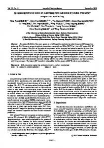
FIG. 2. The HRTEM micrographs of Sample A 共a兲, Sample B 共b兲, and ¯ 0兴 Sample C 共e兲 taken along 关101 sapphire. 共c兲 and 共d兲 are the Fourier-filter images of 共a兲 and 共b兲, respectively. The insets in 共a兲 and 共b兲 are diffraction patterns from the interface layers. FIG. 1. The polarity results by EH, 共a兲–共c兲 for Sample A and 共d兲–共f兲 for Sample B: the hologram of ZnO films 关共a兲 and 共d兲兴, the reconstructed phase image 关共b兲 and 共e兲兴, the averaged one-dimensional phase change profile 关共c兲 and 共f兲兴 obtained from the boxed area in 关共b兲 and 共e兲兴.
Well-defined cubic phase in the nitrided layers was revealed in all samples 共Samples A, B, and C兲, as shown in Fig. 2. The HRTEM images of ZnO/ AlN/ sapphire共Sap. 兲 were taken along 关10-10兴sapphire. The insets of Figs. 2共a兲 and 2共b兲 are the digital diffraction patterns 共DDP兲 of the interlayers obtained by fast Fourier transform of the HRTEM images.1 In order to reduce the noise and minimize blurring, the Fourier-filtered images 关Figs. 2共c兲 and 2共d兲兴 of Figs. 2共a兲 and 2共b兲 were processed by DigitalMicrograph software.15 There is a clear nitridation interlayer 共indicated by the white arrows兲 in both samples. The interlayer consists of ⬃7–8 atomic layers and is verified to be AlN with zinc blende structure by the HRTEM image and the indexed DDP. However, for the two samples, the interlayers are different in that they have different atomic stacking order along the growth direction which leads to the different polarity of the two samples. From Fig. 2, associated with the results of the polarity by EH, the orientation relationships between ZnO, AlN, and ␣-Al2O3 are verified to be ZnO关11-20兴 / / AlN关10 -1兴 / / Sapphire关10-10兴 and ZnO关0001兴 / / AlN关111兴 / / Sapphire关0001兴 for Sample A, and ZnO关11-20兴 / / AlN关10 -1兴 / / Sapphire关10-10兴 and ZnO关000-1兴 / / AlN关1 -11兴 / / Sapphire关0001兴 for Sample B, respectively. Therefore, the polar orientations for Samples A and B are 关111兴 and 关1-11兴, respectively. For the zinc blende structure, the 关111兴 and 关1-11兴 orientations correspond to III polar and V polar, respectively.16 Thus, we can conclude that the 关111兴 and 关1-11兴 orientations correspond to the Al-polar and N-polar AlN, which eventually lead to the subsequent Zn-polar and
O-polar ZnO films, respectively. Figures 2共a兲–2共d兲 also illustrate that the nitridation layers formed at temperatures of 400 °C or lower are unrelaxed. In Figs. 2共c兲 and 2共d兲, the 共020兲 and 共0-20兲 planes 关with 61° to 共111兲 or 共1-11兲 of AlN are shown by three white lines, and the sapphire 共−12-13兲 and 共1-213兲 planes 共with 61° to 共0001兲兴 are also indicated by three white lines below. It is reasonable to think that the AlN 共020兲 planes extend from the sapphire 共−1213兲 in Sample A and the AlN 共0-20兲 planes from sapphire 共1-213兲 in Sample B. Therefore, the AlN interlayer is not relaxed, which is also confirmed by the configuration of misfit dislocations in ZnO/ AlN interface.14 Figure 2共e兲 is the HRTEM image of Sample C also taken along 关10-10兴sapphire. The inversion domains were observed, and the left and right domains of AlN are similar to that of Samples A and B which have an Al and N polarity, respectively. The 共020兲 and 共0-20兲 planes of the two AlN domains are indicated with white lines, and the interfaces of ZnO/ AlN/ Sap.. are arrowed in the figure. Disordered AlN was observed near this inversion domain boundary 共indicated by the small arrow兲. Figure 3 shows the schematic of the atomic arrangements of ZnO on 共0001兲 sapphire with two kinds of AlN interlayers illustrated in Samples A and B, respectively. Our results show that both LT and HT nitridations under optimized nitrogen plasma conditions lead to the formation of a well-defined cubic phase of AlN. It has been well established that the nitridation process begins with the bond formation between the nitrogen atoms and the first Al layer on sapphire surface. The nitridation goes on with the diffusion of nitrogen atoms into sapphire and substitution for oxygen atoms, resulting in the formation of AlN thin layer.17,18 After sufficient exposure to oxygen radicals at LT, oxygenterminated surface of sapphire 共0001兲 is expected. The un-
Downloaded 05 Sep 2005 to 159.226.36.141. Redistribution subject to AIP license or copyright, see http://apl.aip.org/apl/copyright.jsp
051901-3
Appl. Phys. Lett. 87, 051901 共2005兲
Wang et al.
FIG. 3. The schematic representations of the atomic arrangements of ZnO on 共0001兲 sapphire with zinc blende structure of AlN interlayer along 关111兴 direction 共a兲 and 关1-11兴 direction 共b兲 epitaxy.
derlying Al atoms are six coordinated, i.e., binding to three oxygen atoms in topmost layer and another three in the second oxygen layer beneath, as in the bulk.19 When nitridation is performed on this kind of surface at LT, first, nitrogen atoms will replace the topmost oxygen atoms forming AlNO complex which is unstable in term of energy and will change into AlN when nitrogen substitution continues. In this case, a N–Al bilayer is formed with the N layer upward 共i.e., the formation of N-polar AlN film兲. The thickness of AlN layer increases with the nitrogen substitution going on in sapphire substrate and the structure of the N-polar AlN is extended, such is the case of Sample B. On the other hand, Al-terminated surface is expected after HT thermal annealing under ultrahigh-vacuum conditions. For these topmost Al atoms, the coordination will be different from that in bulk. A tetrahedral environment, i.e., binding to three oxygen atoms in the layer below and leaving one dangling bond on the top, will be adopted rather than the octahedral one.19 When nitridation begins on this kind of surface at HT, the substitution of N atoms for the four coordinated underlying oxygen atoms will lead to the formation of an Al–N bilayer with Al layer upward. Therefore, Al-polar AlN film will be formed as the diffusion of nitrogen atoms continues, which is confirmed by Sample A. Therefore, to ensure the uniform O-polar or Zn-polar ZnO films, the combination of sapphire surface pretreatment and nitridation temperature should be selected carefully so as to obtain a uniform coordination of the Al atoms in the first Al layer. Otherwise, the formation of inversion domains will be unavoidable in AlN layer when two kinds of coordination of Al atoms are formed at the initial stage of nitridation, as illustrated in Fig. 2共e兲. When the nitridation is carried out on the Al-terminated surface at LT, part of topmost of Al atom will directly bind with three nitrogen atoms before the diffusion of N atoms into sapphire substrate due to the stronger adsorption of nitrogen atoms in contrast to HT nitridation. Thus, both Al-polar and N-polar domains are formed in the AlN layer, leading to the inversion domain formation in the AlN layer 关Fig. 2共e兲兴. In our experiments, we found distinct growth behaviors for the Zn-polar 共Sample A兲 and O-polar 共Sample B兲 ZnO films due to the different bonding configurations on the Znand O-polar surfaces. A textured morphology was usually formed for the Zn-polar film under stoichiometric or the Zn-
rich conditions. No growth steps were observed, although a relatively smooth surface was obtained under oxygen-rich conditions. On the other hand, the atomic force microscopy image 共not shown here兲 taken on the O-polar sample grown under stoichiometric flux condition showed very smooth surface with steps. A hexagonal morphology with pyramids or pits was formed under the O-rich or Zn-rich condition, respectively. Therefore, quite different optimized growth conditions were obtained for the Zn-polar and O-polar samples, respectively, while the O-polar sample shows a better crystal quality. The full widths at half maximum of X-ray rocking curves of ZnO 共0002兲 and 共10-12兲 -scans are 105 and 390 arcs, respectively 共cf., 180 and 535 arcs for the Zn-polar sample兲. In conclusion, the microstructures of AlN interlayers and their effects on the polarity selection of ZnO epitaxial films were investigated by HRTEM and EH. Cubic AlN layers formed on sapphire substrates were observed in all nitrided samples examined here. It was revealed that different kinds of coordination of Al atoms, near the surface region at the initial stage of nitridation, are attributed to the formation of different polar orientations of the AlN layer. By the careful combination of the sapphire substrate pretreatment and nitridation temperature, the polar orientation of the AlN layer can be steadily controlled. Therefore, uniform O-polar and Znpolar films are obtained. We expect that they should be also useful for III-V nitrides epitaxy. This work was supported by National Science Foundation 共60476044, 60376004, and 60021403兲 and Ministry of Science and Technology 共2002CB613500兲 of China. 1
S. Hong, T. Hanada, H. Ko, Y. Chen, T. Yao, D. Imai, K. Araki, M. Shinohara, K. Saitoh, and M. Terauchi, Phys. Rev. B 65, 115331 共2002兲. 2 Y. Wang, Q. Y. Xu, X. L. Du, Z. X. Mei, Z. Q. Zeng, Q. K. Xue, and Z. Zhang, Phys. Lett. A 320, 322 共2004兲. 3 S.-K. Hong, H.-J. Ko, Y. Chen, T. Hanada, and T. Yao, Appl. Surf. Sci. 159, 441 共2000兲. 4 D. C. Look, D. C. Reynolds, C. W. Litton, R. J. Jones, D. B. Eason, and G. Cantwell, Appl. Phys. Lett. 81, 1830 共2002兲. 5 T. D. Moustakas, R. J. Molnar, T. Lei, G. Menon, and C. R. Eddy, Jr., Mater. Res. Soc. Symp. Proc. 242, 427 共1992兲. 6 X. Q. Wang, H. Iwaki, M. Murakami, X. L. Du, Y. Ishitani, and A. Yoshikawa, Jpn. J. Appl. Phys., Part 2 42, L99 共2003兲. 7 C. Heinlein, J. Grepstad, T. Berge, and H. Riechert, Appl. Phys. Lett. 71, 341 共1997兲. 8 K. Uchida, A. Watanabe, F. Yano, M. Kouguchi, T. Tanaka, and S. Minagawa, J. Appl. Phys. 79, 3487 共1996兲. 9 F. Widmann, G. Feuillet, B. Daudin, and J. L. Rouviere, J. Appl. Phys. 85, 1550 共1999兲. 10 S. Mikroulis, A. Georgakilas, A. Kostopoulos, V. Cimalla, and E. Dimakis, Appl. Phys. Lett. 80, 2886 共2002兲. 11 X. Wang, Y. Tomita, O. Roh, M. Ohsugi, S. Che, Y. Ishitani, and A. Yoshikawa, Appl. Phys. Lett. 86, 011921 共2005兲. 12 Q. Y. Xu, Y. Wang, Y. G. Wang, X. L. Du, Q. K. Xue, and Z. Zhang, Appl. Phys. Lett. 84, 2067 共2004兲. 13 Z. X. Mei, X. L. Du, Y. Wang, M. J. Ying, Z. Q. Zeng, H. Zheng, J. F. Jia, Q. K. Xue, and Z. Zhang, Appl. Phys. Lett. 86, 112111 共2005兲. 14 Z. X. Mei, Y. Wang, X. L. Du, M. J. Ying, Z. Q. Zeng, H. Zheng, J. F. Jia, Q. K. Xue, and Z. Zhang, J. Appl. Phys. 96, 7108 共2004兲. 15 D. Gerthsen, D. Litvinov, Th. Gruber, C. Kirchner, and A. Waag, Appl. Phys. Lett. 81, 3972 共2002兲. 16 T. Mitate, Y. Sonoda, and N. Kuwano, Phys. Status Solidi A 192, 383 共2002兲. 17 F. Dwikusuma and T. F. Kuech, J. Appl. Phys. 94, 5656 共2003兲. 18 P. Vennéguès and B. Beaumont, Appl. Phys. Lett. 75, 4115 共1999兲. 19 T. J. Godin and J. P. LaFemina, Phys. Rev. B 49, 7691 共1994兲.
Downloaded 05 Sep 2005 to 159.226.36.141. Redistribution subject to AIP license or copyright, see http://apl.aip.org/apl/copyright.jsp