Mar 8, 2007 - Pasadena, CA 91125. {frederique,hassibi}@systems.caltech.edu. Abstract. In this paper, we present a coding strategy for half duplex wireless ...
1
Cyclic Distributed Space-Time Codes for Wireless Relay Networks with no Channel Information Fr´ed´erique Oggier and Babak Hassibi1 Department of Electrical Engineering California Institute of Technology Pasadena, CA 91125 {frederique,hassibi}@systems.caltech.edu
Abstract In this paper, we present a coding strategy for half duplex wireless relay networks, where we assume no channel knowledge at any of the transmitter, receiver or relays. The coding scheme uses distributed space-time coding, that is, the relay nodes cooperate to encode the transmitted signal so that the receiver senses a space-time codeword. It is inspired by noncoherent differential techniques. The proposed strategy is available for any number of relays nodes. It is analyzed, and shown to yield a diversity linear in the number of relays. We also study the resistance of the scheme to relay node failures, and show that a network with R relay nodes and d of them down behaves, as far as diversity is concerned, as a network with R − d nodes. Finally, our construction can be easily generalized to the case where the transmitter and receiver nodes have several antennas.
I. P RELIMINARIES Wireless relay networks have recently received a lot of attention. Coding strategies inspired by spacetime coding techniques, where the transmit antennas cooperate to resist the fading, have been proposed, yielding cooperative diversity schemes, where the relay nodes form a virtual multiple antennas array to obtain the diversity advantage known to be achieved by MIMO systems [17], [1], [10], [2], [23], [5], [4]. These works have focused on different aspects of coding for wireless networks. In [2], the capacity of the network is computed, while a lot of work has been done on finding codes optimal with respect to the so-called diversity-multiplexing gain tradeoff [1], [23], [5]. 1
This work was supported in part by NSF grant CCR-0133818, by Caltech’s Lee Center for Advanced Networking and by a grant from the David and Lucille Packard Foundation. Some parts of this paper first appeared in Allerton 2006 and ICASSP07. March 8, 2007
DRAFT
2
A. Previous work on distributed space-time coding In [10], a strategy called distributed space-time coding has been presented. The idea is to have the relay nodes apply a simple operation on their received signal, in such a way that the signal at the receiver appears as a space-time code. This involves a two-step transmission, where the transmitter first broadcasts the information to the relays, and second, the relays forward the received signal after having performed a unitary matrix multiplication on the signal. The pairwise probability of error and the diversity gain of such coding strategy has been computed. Random distributed space-time codes are used, that is, the matrices used at the relays are generated randomly. In [18], [14], [12], distributed space-time codes following the two-step protocol of [10] which reach the diversity with good coding gain have been proposed. In [11], it was argued that in order to increase the data rate of the network, one may use multiple antennas at both the transmitter and the receiver nodes. The two-step transmission of [10] has been generalized, and the diversity and coding gain of random distributed space-time codes in the multiple antenna nodes scenario has been computed. Algebraic distributed space-time codes for multiple antenna nodes reaching the diversity and having a better coding gain than random codes have been presented in [19]. Recently, the setting of [10] has been generalized in [16], where the constraint of unitary matrix multiplication at the relays has been relaxed. In [4], a different two-step protocol to implement distributed space-time code has been presented. During the first phase, the source sends a signal and the relays decode their received signal if the channel was not in outage. During the second phase, the relays which decoded cooperate to encode a space-code. The receiver knows the received signals from both the phases, and decode accordingly. This gives a practical scheme, following the scheme of [17], where the code construction is based on information theoretic arguments. All the above strategies assume a “coherent” channel in the sense that the receiver knows all the channel paths occuring during communication. Recently, different authors started to investigate coding for a “noncoherent” channel, assuming that none of the transmitter, relay nodes nor receiver, knows about the channel. A natural approach has been to recall what are the techniques used for the noncoherent MIMO channel. B. Previous differential coding techniques Unitary differential modulation is a technique to code for noncoherent MIMO channels [7], [9]. By asking the transmitter to send at each time t a codeword multiplied by what was sent at time t − 1, March 8, 2007
DRAFT
3
differential modulation yields a decoding strategy that does not depend on the channel, and which is thus suitable for a noncoherent channel. Using a similar approach for wireless networks has been investigated by several authors. In [24], differential modulation has been adapted for a decode-and-forward strategy. Differential distributed spacetime coding when the nodes do not decode has been proposed independently in [15], [20], [13], in the single antenna case. The works in [15], [13] consider a joint design of the matrices at the relays with the transmitted signal, while the work in [20] suggests a construction where the matrices at the relays are fixed first, while the transmitted signal is optimized independently. C. Contribution and organization of the paper In this work, we are interested in designing a coding strategy for wireless networks where we assume no channel information, that is, the transmitter and the relays are assumed not to know the channel, and the receiver decodes with no knowledge of the different paths used during communication. We furthermore consider a network where nodes are small devices with few resources, so we do not assume that they are able to decode. Instead, they just do a simple operation on the received signal for which they do not need to know the fadings. Our strategy is inspired by noncoherent MIMO unitary differential modulation. We will consider both the cases when the transmitter and receiver have one or several antennas. Our construction is valid for any number of relays, and any number of transmit/receive antennas. We organize this paper as follows. In Section II, we start by recalling the wireless network we consider, and how distributed coding is performed. We then present a distributed coding strategy that emulates communication over a noncoherent MIMO channel. This allows us to define a differential coding strategy, described in Section III. For convenience, the idea behind differential modulation is recalled. In Section IV, we propose a mismatched decoder and show that this yields a diversity gain linear in the number of relays. We further analyze the behavior of the proposed coding strategy in case of node failures. In Section V, we discuss issues related to code constructions and we provide simulation results. Finally we show that our construction can be generalized to the case when both the transmitter and receiver nodes have several transmit antennas. II. N ONCOHERENT D ISTRIBUTED S PACE -T IME C ODING A. Distributed space-time codes Following the setting defined in [10], consider a wireless network with R+2 nodes which are randomly and independently distributed. Two nodes, a receiver and a transmitter, want to communicate, while the March 8, 2007
DRAFT
4
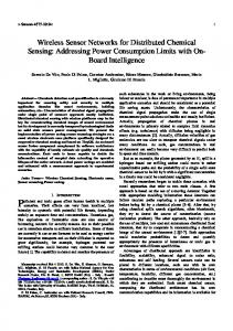
R other nodes serve as relays. Every node is equipped with a single antenna. It can transmit and receive,
but not simultaneously. The channels are denoted by fi from the transmitter to the ith relay, and by gi from the ith relay to the receiver (see Fig. 1). Both channels are assumed independent complex Gaussian CN (0, 1). We assume a coherence interval of length T ≥ R (there is no need to have more relays than
coherence time, since it is shown in [10] that the diversity of the system depends on min{T, R}). The total power of the system ρ is equally distributed between the transmitter and the relays, so that the transmitter has an energy of P1 = ρ/2, while each relay has P2 = ρ/(2R). The transmission is done in two steps: •
Step 1: at the transmitter. Let s = (s1 , . . . , sT )t be the signal to be sent, from the codebook {s1 , . . . , sL } of cardinality L. The vector s is normalized such that E[s† s] = 1. Let P1 be the
average power available for each transmission. From time 1 to T , the transmitter sends the signals √ P1 T s to each relay. The received signal at the ith relay is given by ri =
p
P1 T fi s + vi , i = 1, . . . , R,
(1)
where vi is the complex Gaussian noise CN (0, 1) at the ith relay.
•
Step 2: at the relays. The ith relay multiplies its received signal by a unitary matrix A i (see Remark 1), and sends from time T + 1 to 2T the signals ti to the receiver, where r P2 A i ri , ti = P1 + 1
(2)
and the normalization factor is chosen so that E[t†i ti ] = P2 T . The signal at the receiver is given by: y=
R X
gi ti + w,
(3)
i=1
where w is the complex Gaussian noise CN (0, 1) at the receiver.
Remark 1: In order to have an equitable protocol among different users and among different times instants, the matrices Ai are assumed unitary. This also guarantees that the noise w at the receiver remains temporally white. Note that it has been shown recently [16] that for that purpose, it is enough to require the Ai vi , i = 1, . . . , R to be uncorrelated. From (3), (2) and (1), the received signal is given by r P1 P2 T y= SH + W, P1 + 1
March 8, 2007
(4)
DRAFT
5
relays r1 t1 f1 transmitter f2
r2
t2
g1 g2
s gR
fR tR
rR Fig. 1.
receiver x
The single antenna wireless relay network model
with S = [A1 s · · · AR s], H = [f1 g1 , . . . , fR gR ]t
and W =
r
(5)
R
P2 X gi Ai vi + w. P1 + 1 i=1
The T × R matrix S works like a space-time code in a multiple-antenna system. It is called a distributed
space-time code since it has been generated in a distributed way by the relay nodes. B. A noncoherent channel Let us now consider the equation y=
r
P1 P2 T SH + W, P1 + 1
derived above, but assume that none of the fadings are known. In a traditional noncoherent MIMO setting, it has been argued [6] that the transmitted codeword S has to be unitary. Recall that here S = [A1 s, . . . , AR s].
The aim is now to design the signal constellation {s1 , . . . , sL } 3 s and the unitary matrices Ai , i = 1, . . . , R, so that the T × R matrix S is unitary, i.e, S † S = IR . Let
1 s0 = √ (1, . . . , 1)t , si = Ui s0 , i = 1, . . . , L, T
where Ui ’s are T × T unitary matrices and s0 is normalized so that E[s† s] = 1. March 8, 2007
DRAFT
6
Assume now that there exists a T × T matrix M such that M M † = T . We can then choose the
matrices Ai to be
Ai = diag(Mi ), i = 1, . . . , R,
where Mi denotes a column of M (recall that T ≥ R). Let Uj , j = 1, . . . , L, be diagonal unitary matrices,
thus commuting with all Ai . We have, when sending the codeword sj , that the corresponding distributed space-time codeword Sj is given by √ Sj = [A1 sj , . . . , AR sj ] = [Uj A1 s0 , . . . , Uj AR s0 ] = Uj M/ T ,
and Sj† Sj = M † Uj† Uj M/T = IR for all transmitted signal sj . Let us keep in mind that the matrices Ai have to be unitary. Such matrices M can be found in the class of Butson-Hadamard matrices (see for example [8]). Definition 1: A Generalized Butson-Hadamard (GBH) matrix is a T × T matrix M with coefficients
in a ring such that
M M ∗ = M ∗ M = T IT
where M ∗ is the transpose of the matrix of inverse elements of M : m∗ij = m−1 ji . If the coefficients of M are chosen to be roots of unity, then m−1 ij = mij , i.e., the inverse is the conjugate, so that M M † = M † M = T IT .
Furthermore, this implies that all matrices Ai are unitary, i = 1, . . . , R. Example 1: Let ζ3 = exp(2iπ/3) be a primitive 3rd root of unity. Then the matrix 1 1 1 2 M = 1 ζ 3 ζ3 1 ζ32 ζ3
is a Butson-Hadamard matrix. It is easy to check that M M † = 3I3 . Also 1 0 0 1 0 0 1 0 0 diag(M1 ) = 0 1 0 , diag(M2 ) = 0 ζ3 0 , diag(M3 ) = 0 ζ32 0 0 0 ζ3 0 0 ζ32 0 0 1
are clearly unitary.
Other examples of such matrices can be found in [8]. Note that the tensor product of two GBH matrices March 8, 2007
DRAFT
7
is again a GBH matrix. This is thus a convenient way of building GBH matrices for a any dimension T . Example 2: The following tensor product 1 1 1 1 1 1 M ⊗ M = 1 ζ3 ζ32 ⊗ 1 ζ3 ζ32 1 ζ32 ζ3 1 ζ32 ζ3
is a Butson-Hadamard matrix that can be used for a network with 9 relay nodes. Note that our strategy has the advantage of having independent designs for the matrices Ai and Uj , unlike for example the scheme given in [15]. Thus, for a given number of relays R, the matrices are built once for all and given to the relays. The code design then simplifies to considering the matrices Uj . This question is addressed in Section V.
III. A D IFFERENTIAL C ODING S TRATEGY In this section, we give a strategy to implement a differential distributed coding scheme (for the sake of completeness, the standard differential scheme for MIMO channel is recalled below). It is a priori not clear how to emulate differential coding in a distributed setting. Where should the differential encoding take place? One can imagine the relays cooperating to encode differentially, similarly to the coherent case where relays encode the space-time codes, as well as having the transmitter itself collaborating with the relays. However, the construction presented in the previous section clearly suggests the approach where the differential encoder is actually at the transmitter itself. The relays cooperate not to encode differentially, but to encode a unitary space-time code. A. Differential MIMO coding Consider a Rayleigh flat fading channel with M transmit antennas and N receive antennas, with unknown channel information. The channel is used in blocks of M channel uses, so that the transmitted signal can be represented as an M × M matrix St , where t = 0, 1 . . . represents the block channel use.
If we assume that the channel is constant over M channel uses, we may write it as Yt =
√
ρSt Ht + Wt , t = 0, 1, . . .
(6)
Here Ht , the channel matrix, and Wt , the noise matrix, are two M × N matrices with independent complex normal coefficients, and ρ is the expected SNR at each receiver antenna.
March 8, 2007
DRAFT
8
Differential unitary space-time modulation [7], [9] is implemented by sending at time t a new codeword multiplied by the signal transmitted at time t − 1. The transmitted signal St is thus (assuming S0 = I) (7)
St = Xzt St−1 , t = 1, 2, . . . ,
where zt ∈ {0, . . . , L − 1} is the data to be transmitted, and C = {X0 , . . . , XL−1 } the constellation to
be designed. It can be seen from the above equation that the codebook has to contain unitary matrices, to prevent St to tend either to zero or infinity. If we further assume the channel constant for 2M consecutive uses, we get from (6) and (7) that Yt =
√
ρXzt St−1 H + Wt
= Xzt (Yt−1 − Wt−1 ) + Wt = Xzt Yt−1 + Wt0 ,
where Wt0 = Wt − Xzt Wt is statistically independent of Xzt , since Xzt is unitary. Since the matrix
H does not appear in the last equation, this means that differential modulation allows decoding without
knowledge of the channel. Remark 2: Note that in practice, the coherence interval is usually much larger than 2M . In fact, what is often encountered is a continuously-fading channel. The assumption that the differential scheme exploits is that the channel is roughly constant over “any” 2M channel uses. B. A differential encoder It is straightforward to adapt the two-steps transmission described in Subsection II-A to allow differential encoding and decoding. Assume that the transmitter wants to send at time t + nT the data zt+nT . It is encoded into a unitary matrix U (zt+nT ). We consider the following strategy: √ 1) Let st = U (zt )s0 be the signal to be transmitted, where s0 = (1, . . . , 1)t / T is normalized so that E[s†t st ] = 1. Let P1 be the average energy available for each transmission. From time t + 1 to √ t + n, the transmitter sends the signal P1 T st to each relay. From time t + T + 1 to t + 2T , the
signal to be transmitted is st+T = U (zt+T )st . 2) At the ith relay, the received signals are (indexing the signals as a function of the time at which they have been sent) ri (t) = March 8, 2007
p
P1 T fi st + vi (t), i = 1, . . . , R, DRAFT
9
and ri (t + T ) =
p P1 T fi U (zt+T )st + vi (t + T ), i = 1, . . . , R.
3) The ith relay multiplies its received signal by a unitary matrix Ai , where Ai has been built using a Butson-Hadamard matrix as described in Subsection II-B. From time t + T + 1 to t + 2T , q 2 Ai ri (t), and similarly from time t + 2T + 1 to t + 3T : the transmitted signal is ti (t) = P1P+1 q 2 ti (t + T ) = P1P+1 Ai ri (t + T ) .
4) At time t + 2T , resp. t + 3T , the received signals are similar to (4)-(5): y(t) =
√
cρ
R X
(8)
gi fi Ai st + W (t)
i=1 R
√ X cρ y(t + T ) = gi fi Ai U (zt+T )st + W (t + T ),
(9)
i=1
where
W (t) =
r
R
P2 X P2 P1 T . gi Ai vi (t) + w(t) and cρ = P1 + 1 P1 + 1 i=1
Under the assumption that Ai and U (zt+T ) commute, for all i and for all possible choices of U (zt+T ), we can plug equation (8) into equation (9), which yields y(t + T ) = U (zt+T )y(t) + [W (t + T ) − U (zt+T )W (t)].
(10)
Note that the channel coefficients fi and gi do not appear in (10). Also, the assumption that Ai and U (zt+T ) commute is valid since both the unitary codewords Uj and the matrices Ai are chosen diagonal.
IV. PAIRWISE P ROBABILITY
OF
E RROR
AND
N ODES FAILURES
A. A decoding rule Emulating the point to point case, a natural candidate for the differential decoder is arg
min
Ul , l=1,...,L
ky(t + T ) − Ul y(t)k2 .
(11)
Let us restrict to the case where T = R. In order to analyze this strategy, we consider two instances of the noncoherent channel, y(t) =
March 8, 2007
√
cρ S(t)H + W (t)
DRAFT
10
where H is an T × T matrix unknown at both the transmitter and receiver, S(t) is a T × T unitary matrix, and cρ is a constant which depends on the SNR ρ, that is, S(t) y(t) W (t) H + = √cρ . S(t + T ) y(t + T ) W (t + T )
Since S(t) and S(t)ψ are indistinguishable for an arbitrary unitary T × T matrix ψ , we preprocess the
signal so that
y(t) y(t + T )
=
√
cρ
IT Uk
H +
W (t) W (t + T )
,
for Uk a unitary matrix belonging to the codebook. To suit the network model, we have W (t) =
r
T
P2 X Ai gi vi (t) + w(t) P1 + 1 i=1
and H = Dg f , where Dg = diag(g1 , . . . , gT ) and f = (f1 , . . . , fT )t . Furthermore, we have cρ = and we denote c0ρ =
P2 P1 +1 .
P2 P1 T P1 +1 ,
Recall that P1 = ρ/2, P2 = ρ/(2R) and ρ is the total power of the system.
Because of the two steps transmission, both the noise W (t) and the channel matrix H contains products of Gaussian random variables, which makes a precise analysis difficult. In this work, we thus consider a mismatched decoder, and we will show that such a decoder already gives the diversity. B. Pairwise probability of error Let us now compute the pairwise error probability of decoding with a mismatched decoder. Let In denote the identity matrix of size n. Knowing g = (g1 , . . . , gT )t , we have E[W (t)W (t)† ] = E[W (t + T )W (t + T )† ] = c0ρ E[
T X
Ai gi vi (t)(Aj gj vj (t))† ] + E[W (t)W (t)† ]
i,j=1
= c0ρ =
T X
Ai A†i |gi |2 IT + IT
i=1 0 (cρ kgk2
+ 1)IT .
Let y = [y(t) y(t + T )]t , we have cρ D|g| + (c0ρ kgk2 + 1)IT † Σ := E[yy ] = cρ D|g| Uk March 8, 2007
cρ D|g| Uk† cρ D|g| + (c0ρ kgk2 + 1)IT
, DRAFT
11
where D|g| = diag(|g1 |2 , . . . , |gT |2 ).
The pairwise probability of error is given by P (Uk → Ul ) = P (ky(t + T ) − Uk y(t)k2 ≥ ky(t + T ) − Ul yk2 | Uk is sent) = P (k[−Uk IT ] yk2 ≥ k[−Ul IT ] yk2 | Uk is sent) = P (y† Uy ≥ 0 | Uk is sent)
with k 6= l and
U=
Ul†
0 Ul − U k
− 0
We start by computing P (y† Uy ≥ 0) knowing g.
Uk†
.
(12)
Proposition 1: We have that, at high SNR, P (y† Uy ≥ 0| g) ≤
Proof: We have
cρ 1 det(IT + 1 D|g| (Uk − Ul )(Uk − Ul )† )−1 . 2 8( T kgk2 + 1)
P (y† Uy ≥ 0| g) = E[u(y† Uy)] # " Z ∞ iωy† Uy e 1 dω = E 2π −∞ iω
where u is the step function (u(x) = 1 if x > 0, u(x) = 0 else), and the second equality is the Fourier transform of u. Computing the expectation yields Z Z ∞ iωy† Uy † −1 e 1 e−y Σ y P (y† Uy ≥ 0| g) = dωdy 2π iω (2π)2T det(Σ) −∞ Z ∞ Z −y† (−iωU+Σ−1 )y 1 e = dydω. 2T +1 (2π) i −∞ ω det(Σ) Since the exponent of the exponential is of the form iy † ωUy − y† Σ−1 y, with real part −y† Σ−1 y which
is negative, and imaginary part given by iy† ωUy (recall that U is Hermitian), then this integral converges and we have 1 P (y Uy ≥ 0| g) = 2πi †
Z
∞ −∞
1 dω. ω det(I − iωUΣ)
We have that the above determinant is given by T Y ¡
k=1
March 8, 2007
¢ 1 + iωcρ |gk |2 |uik − ujk |2 + ω 2 |uik − ujk |2 (2acρ |gk |2 + a2 ) , DRAFT
12
where a = c0ρ kgk2 + 1. Since our goal is a diversity computation, we are interested in an very high SNR regime. Note that when ρ is big, c0ρ =
P2 P1 +1
=
ρ T (ρ+2)
a2 does not depend on ρ, so that we have det(I − iωUΣ) ≈
T Y
k=1
2
cρ |gk | |uik − ujk |
2
→ 1/T . Thus a → kgk2 /T + 1 and the term in
µ
¶ 1 2 + iω + ω 2a . cρ |gk |2 |uik − ujk |2
By completing the squares, we get that P (y† Uy ≥ 0| g) is given by 1 2πi
Z
∞ −∞
Ã
1 ω
where
T Y
k=1
cρ |gk |2 |uik − ujk |2 2a
ck :=
s
"µ
i ω+ 4a
¶2
+ c2k
#!−1
dω
1 1 + . 2 2 16a cρ |gk | |uik − ujk |2
Note that the above integral has poles in ω = −i(1/4a ± ck ). Thus as long as −i(1/4a − ck ) < Im(ω) < −i(1/4a + ck ), the above integral is well-defined. We thus choose the following contour of integration,
within the convergence region 1 2πi
Z
i ∞− 4a i −∞− 4a
1 ω
Ã
T Y
k=1
cρ |gk |2 |uik − ujk |2 2a
"µ
i ω+ 4a
¶2
+ c2k
#!−1
dω
and with a change of variable, we get 1 2πi
Z
∞ −∞
1 i ω − 4a
Ã
T Y
k=1
·
1 1 cρ |gk | |uik − ujk | 2a ω + + 2 2 16a cρ |gk | |uik − ujk |2 2
2
2
¸!−1
dω
Following [6], we obtain a bound on the probability of error that we know real by taking the real part of the above expression: †
P (y Uy ≥ 0| g) / ≤ =
!−1 ¸ 1 dω cρ |gk | |uik − ujk | 2a ω + +1 16a2 −∞ k=1 Ã T !−1 Z ∞ Y 1 1 4adω cρ |gk |2 |uik − ujk |2 +1 2π −∞ 1 + 16a2 ω 2 8a k=1 Ã T !−1 1 1 Y cρ |gk |2 |uik − ujk |2 +1 2 8a 1 2π
Z
∞
4a 1 + 16a2 ω 2
Ã
T Y
2
2
·
2
k=1
=
March 8, 2007
cρ 1 D|g| (Uk − Ul )(Uk − Ul )† )−1 . det(IT + 1 2 2 8( T kgk + 1)
DRAFT
13
Thus P (Uk → Ul ) = Eg P (y† Uy ≥ 0 | g) ≤ Eg det(IT +
cρ 1 8( T kgk2
+ 1)
D|g| (Uk − Ul )(Uk − Ul )† )−1 .
This bound on the pairwise probability of error is similar to the Chernoff bound obtained in [10, Theorem 1], where it has been proven, by computing the above expectation on g = (g1 , . . . , gT ), that the diversity ³ ´ gain is given by rank((Uk − Ul )(Uk − Ul )† ) 1 − logloglogP P . Thus when (Uk − Ul )(Uk − Ul )† is full rank
(that is, the code is fully diverse), we get a diversity of µ ¶ log log P . R 1− log P
(13)
C. Analysis of node failures In our network setting, relay nodes are small devices with few power. It is thus very likely that some of them may run out of battery, or may encounter a technical problem that will prevent them to communicate, at a given point of the transmission. In this part, we are interested in understanding how a coding strategy designed for R relay nodes will behave if d of them are down. Let us consider one step of the differential scheme, thus involving two transmissions, say y(t) and y(t + T ). Let us assume that y(t) is transmitted correctly, but one or several node failures happen
while transmitting y(t + T ). Denote by D the set of indices of relay nodes which are down during the transmission of y(t + T ). In Equation (9) for y(t + T ) we thus have R X
gi fi Ai U (zt+T )st =
i=1
X
gi fi Ai U (zt+T )st .
i6∈D
In Equation (8) for y(t), we can similarly write R X
g i fi A i s t =
i=1
X i6∈D
g i fi A i s t +
X
g i fi A i s t ,
i∈D
so that when we plug Equation (8) inside Equation (9), the term the codeword Uzt+T will not be recovered.
P
i∈D gi fi Ai st
adds to the noise, and
However, during the next step, things are different. Consider now the step involving y(t + T ) and y(t + 2T ). Now, for both signals, the same set of relay nodes will be down. Thus communication will
take place over a network where actually R − |D| are transmitting. The expression for y(t + T ) and y(t + 2T ) are similar to those obtained in Equations (8) and (9), except that the sums are over i ∈ R\D
March 8, 2007
DRAFT
14
R 3 3 6 6 9
L 8 63 64 4096 57
rate 1 1.99 1 2 0.65
ζ(U ) 0.5134 0.3301 0.3792 0.1428 0.361
u u = (1, 1, 3) u = (1, 17, 26) u = (1, 7, 15, 23, 25, 31) u = (1, 599, 623, 1445, 1527, 1715) u = (1, 4, 16, 7, 28, 55, 49, 25, 43)
TABLE I S OME CYCLIC CODES WITH GOOD DIVERSITY PRODUCT.
instead of i = 1, . . . , R. We thus expect the diversity of such systems to be µ ¶ log log P (R − d) 1 − , logP
(14)
where d = |D|. This is a positive result, since it says that the strategy is resistent to node failures. V. C ODE C ONSTRUCTIONS
AND
S IMULATION R ESULTS
In this section, we first consider code constructions, and show that though any random diagonal unitary matrix could be used to generate a codebook, codes designed to optimize the diversity product reach a much better coding gain. We then provide simulation results, also including the node failures scenario. We finally discuss the decoding issue. A. Cyclic codes Since the matrices Ai used at the relays are fixed for a given number of relays R, designing codes consists of constructing the diagonal unitary matrices U (z) in which the data z to be sent will be encoded. Regarding the PEP computation (13), the matrices U (z) have to satisfy the full diversity criterion: det(U (zt ) − U (zt0 )) 6= 0, t 6= t0 .
A priori, any diagonal unitary matrix could be use to build the code, and we furthermore expect that such matrix generated randomly would yield full diversity. This makes our scheme attractive since it is thus available easily for any number of relay nodes R. In order now to reach a good coding gain, one need, similarly to the point to point case, to maximize the diversity product, given by 1 ζ(U ) = min0 | det(U (zt ) − U (zt0 ))|1/R . t6=t 2 March 8, 2007
DRAFT
15 0
10
R=3,cyclic rate 1 R=3,random rate 1
−1
BLER
10
−2
10
−3
10
12
14
16
18
20
22
24
26
P(dB)
Fig. 2.
A random rate 1 code versus a cyclic rate 1 code.
Diagonal unitary codes achieving good diversity product have already been studied in [7] for the MIMO case. They are called cyclic codes. Denote by ζL = exp(2iπ/L) a primitive Lth root of unity. A cyclic code is parametrized as follows:
ζLu1 l 0 0
..
0
.
0 ζLuM l
, l = 0, . . . , L − 1,
where L and u = (u1 , . . . , uM ) have to be designed. Note that M denotes the number of antennas in the point to point case, or the number of relays R in the distributed case. Let us give an example with three relay nodes. Let ζ63 = exp(2iπ/63). The codebook is ζ 0 63 17 Di , D = 0 ζ63 0 0
for i = 1, . . . , 63. Thus L = 63 and u = (1, 17, 26).
given by 0 0 ζ 26 63
Table I summarizes some good cyclic codes. The codes for 3 and 6 relays have been found in [7]. However, no cyclic code in bigger dimension is available, since there is no need for more than 6 antennas in a point to point setting. The code for 9 relays is the diagonal component of a fixed point free group based code [22]. March 8, 2007
DRAFT
16 0
0
10
10
R=3 R=6 −1
10
−2
10
−1
10 −3
BLER
BLER
10
−4
10
−5
10
−2
10 −6
10
−7
10
R=3 nocoding R=3 R=6 nocoding R=6 R=9
−8
10
−3
12
14
16
18
20
22
24
P(dB)
Fig. 3.
26
10
12
14
16
18
20
22
24
26
P(dB)
On the left, rate 1 cyclic codes: with and without coding at the relays. On the right, rate 2 cyclic codes.
In Fig. 2, we compare a random code with a cyclic code. We plot the block error rate (BLER) as a function of the power of the system in dBs. We consider the cyclic code u = (1, 1, 3) with rate 1, with a random code of rate 1. The random code consists of generating one random unitary diagonal matrix and take its powers from 1 to 8. The relays 1 A1 = I 3 , A2 = 0 0
Ri , i = 1, 2, 3, use respectively the matrices 0 0 1 0 0 2 , A = ζ3 0 0 ζ3 0 . 3 2 0 ζ3 0 0 ζ3
Both codes are fully diverse, but clearly, the cyclic code with high diversity product reaches a much better coding gain. On the one hand, there is thus a real coding gain that could be achieved by choosing carefully the diagonal matrices. On the other hand, since random unitary diagonal matrices yield full diversity, the differential coding scheme we propose is available for any number of relay nodes. B. Illustration of the diversity Simulation results in Fig. 3 show the BLER as a function of P , the power of the system in dBs. To start with, Fig. 3 on the left first show what we already know: there is really a need for coding at the relays, without which we cannot get diversity. We see clearly that without coding at the relays, having 3 or 6 relays in the system does not change the curve and thus give no diversity.
Recall that the analysis of the PEP in (13) predicts a diversity which is linear in the number of relays. March 8, 2007
DRAFT
17 0
0
10
10 R=6 R=6,1 node down R=6,2 nodes down R=6,3 nodes down
R=6,3 nodes down R=3,rate 1
−1
10
−1
10 −2
BLER
BLER
10
−3
10
−2
10
−4
10
−5
10
12
−3
14
16
18
20
22
24
26
10
12
14
16
P(dB)
18
20
22
24
26
P(dB)
Fig. 4. On the left, a network of 6 relay nodes with up to 3 nodes down, on the right, a 6 nodes network with 3 nodes down versus a 3 nodes network.
Fig. 3 on the left further shows how the diversity is increasing, by going from 3 to 6, and then to 9 relays. The codes used are the two cyclic rate 1 codes given in Table I for resp. 3 and 6 relays, and the cyclic code for 9 relays with rate 0.65. Fig. 3 on the right shows simulation results for rate 2 cyclic codes, with resp. 3 and 6 relay nodes. Clearly, increasing the rate decreases the performance, and in particular, the slope given by the diversity starts at high power. Note that this crossing of the two curves was already observed in the point to point case [7], but at a lower SNR. C. Resistance to node failures We finally give simulation results to illustrate the behavior in case of node failures. The analysis done in Section IV shows that as far as diversity is concerned, a network of R relay nodes having d relays not communicating behaves as a network with R − d nodes. This behavior can be observed in Fig. 4. On the left, the performance of a network with 6 relay nodes is shown. Simulations are then done, assuming that
1, then 2, and finally 3 relay nodes are down. We see how the curves change linearly with the number
of relay nodes. Fig. 4 on the right compares a network with 6 relay nodes, but only 3 of them communicating, with a network having only 3 nodes. We observe the same diversity, which was predicted by the analysis in (14). However, there is a clear loss in coding gain, which is expected. The simulation results of this section thus confirm a good behavior of the proposed strategy when March 8, 2007
DRAFT
18
f11 f12
f1R Tx
r1
t1
r2
t2
g1N Rx
fM 1 fM 2 fM R
gR1 gRN rR
Fig. 5.
g11
tR
A wireless network with multiple antenna nodes.
facing node failures. D. Decoding issues We finally briefly discuss decoding issues. Simulations shown in this paper have been done via exhaustive search. Indeed, for such rates, there is no real complexity problem in doing an exhaustive search. However, when increasing the number of relays or the rate, one may need to have a faster algorithm. Recall that the mismatched decoder (11) is given by arg
min
Ul , l=1,...,L
ky(t + T ) − Ul y(t)k2 = arg min
l=1,...,L
R X k=1
|y(t + T )k − ζLuk l y(t)k |2 .
This minimization problem has already been studied in [3], where the authors show how the problem can be expressed as a lattice reduction problem. They give an algorithm to solve it, which is faster than exhaustive search. VI. G ENERALIZATION
TO
M ULTIPLE A NTENNAS C ASE
In [11], a generalization of the network presented in Subsection II-A was given. In order to increase the data rate of the network, both the transmitter and receiver nodes are equipped with multiple antennas (see Fig. 5). Let M and N be the number of transmit resp. receive antennas. The codeword S sent at the transmitter is normalized such that E[Tr(SS† )] = M . Channels are denoted by fmj from the mth transmit antenna to the j th relay and gjn from the j th relay to the nth receive antenna (see Fig. 5), which are assumed to be iid CN (0, 1). Similarly, let vi and Wi be the noise vectors,
with coefficients also iid CN (0, 1). Matrices at the relays are denoted by Ai , i = 1, . . . , R, and need
to be unitary, as before. The power at the transmitter for each transmission is P1 , thus P1 /M for each
March 8, 2007
DRAFT
19
antenna. Each relay has a power of P2 /R for each transmission. By defining Y = [y1 , y2 , . . . , yN ], S = [A1 S A2 S . . . AR S], gi = [gi1 , gi2 , . . . , giN ], H = [f1 g1 , . . . , fR gR ]T , and # "r r R R P2 X P2 X gi1 Ai vi + w1 , . . . , giN Ai vi + wN , W = P1 + 1 P1 + 1 i=1
i=1
it was shown in [11] that the channel model can be written as s P1 P2 T Y = SH + W. (P1 + 1)M
(15)
The received matrix Y is a T × N matrix, while S is a T × M R matrix, since the Ai , i = 1, . . . , R, are
T × T matrices, and S is a T × M matrix.
We now show how the noncoherent scheme presented previously generalizes to the multiple antenna
scenario. A. The noncoherent channel Similarly to what we have done in Subsection II-B, we now need to design the matrices Ai , i = 1, . . . , R and the codebook such that S = [A1 S, . . . , AR S] is unitary, i.e, S † S = IM R . First, we choose the codewords to be of the form Sj = Uj S0 , j = 1, . . . , L
where Uj is a unitary T ×T matrix, and S0 is an initial transmitted signal normalized to that E[Tr(S†j Sj )] =
M for all j = 1, . . . , L. As for the one antenna case, we require that both the unitary matrices Ai , i = 1, . . . , R, and Uj , j = 1, . . . , L be diagonal. Thus, denoting by Sj = [A1 Sj , . . . , AR Sj ], we have Sj† Sj
= [A1 Uj S0 , . . . , AR Uj S0 ]† [A1 Uj S0 , . . . , AR Uj S0 ] = [A1 S0 , . . . , AR S0 ]† Uj† Uj [A1 S0 , . . . , AR S0 ] = [A1 S0 , . . . , AR S0 ]† [A1 S0 , . . . , AR S0 ]
and the fact that Sj is unitary only depends on the choice of the matrices at the relays and the transmitted signal S0 . We thus design the matrices Ai and S0 independently of the codebook of matrices Uj . Suppose now that we have T = M R, with M the number of transmit antennas, R the number of relays, and T the coherence time. Choose a first generalized Butson-Hadamard (GBM) matrix A of size R × R, and a second one B of size M (c.f. Definition 1), both with coefficients that are roots of unity. March 8, 2007
DRAFT
20
Take Ai = diag(a1i , . . . , a1i , . . . , aRi , . . . , aRi ), | | {z } {z } M
M
which is unitary for all i since all aij ’s are roots of unity, and similarly b1,1 . . . b1,M .. .. . . bM,1 bM,M √ M .. .. 0 S = . . , kS0 kF b . . . b 1,1 1,M . .. . . . bM,1 bM,M where
k · kF ,
√
M kS0 kF
is the normalization factor such that E[Tr(S0† S0 )] = M . By definition of the Frobenius norm v uM T uX X √ 0 kS kF = t |s0i,j |2 = M T , i=1 j=1
since all coefficients s0i,j are roots of unity. By construction
1 [A1 S0 , . . . , AR S0 ] = √ A ⊗ B, T
and [A1 S0 , . . . , AR S0 ]† [A1 S0 , . . . , AR S0 ] =
RM IRM = IRM , T
since A ⊗ B is a GBH matrix of size RM .
Example 3: Let M = 2 and R = 3. Choose the following matrices: 1 1 1 1 1 . A = 1 ζ3 ζ32 and B = 1 −1 1 ζ32 ζ3
The unitary matrices at the relays are given by
A1 = I6 , A2 = diag(1, 1, ζ3 , ζ3 , ζ32 , ζ32 ), A3 = diag(1, 1, ζ32 , ζ32 , ζ3 , ζ3 ),
March 8, 2007
DRAFT
21
where I6 denote the identity matrix of size 6, and the initial 1 1 1 −1 r 1 1 2 0 S = 12 1 −1 1 1 1 −1
transmitted signal is .
B. Decoding and Diversity A differential encoder is done similarly to the one antenna case, so that a natural candidate for the differential decoder is arg
min
Ul , l=1,...,L
kY (t + T ) − Ul Y (t)k2 .
Let us restrict to the case where T = M R. Similarly to the single antenna case, in order to analyze this strategy, we consider two instances of the noncoherent channel, Y (t) =
√
cρ S(t)H + W (t)
where H is an T × N matrix unknown at both the transmitter and receiver, S(t) is a T × T unitary
matrix, and cρ is a constant which depends on the SNR ρ, that is, S(t) Y (t) W (t) H + = √c ρ . S(t + T ) Y (t + T ) W (t + T )
Since S(t) and S(t)ψ are indistinguishable for an arbitrary unitary T × T matrix ψ , we preprocess the
signal so that
Y (t) Y (t + T )
= √c ρ
IT Uk
H +
W (t) W (t + T )
,
for Uk a unitary matrix belonging to the codebook. To suit the network model, we have "r # r R R P2 X P2 X W (t) = gi1 Ai vi (t) + w1 (t), . . . , giN Ai vi (t) + wN (t) , P1 + 1 P1 + 1 i=1
i=1
H = [f1 g1 , . . . , fR gR ]T , with fi = [f1i , . . . , fM i ]T and gi = [gi1 , gi2 , . . . , giN ]. Furthermore, we have cρ =
P2 P1 T (P1 +1)M ,
and we denote c0ρ =
P2 P1 +1 .
Recall that P1 = ρ/2, P2 = ρ/(2R) and ρ is the total power
of the system. Since the columns of the matrix H are dependent, we cannot treat the channel equation in March 8, 2007
DRAFT
22
matrix form and have to vectorize it to do the analysis. We denote by vec(Y (t)) the T N × 1 vectorized
version of Y (t). Set Y = [vec(Y (t)), vec(Y (t + T ))]t . The pairwise probability of error is thus given by P (Uk → Ul )
= P (kvec(Y (t + T )) − (Uk ⊗ IN )vec(Y (t))k2 ≥ kvec(Y (t + 1)) − (Ul ⊗ IN )vec(Y (t))k2 | Uk sent)
= P (k[−(Uk ⊗ IN ) IT N ] Yk2 ≥ k[−(Ul ⊗ IN ) IT N ] Yk2 | Uk is sent) = P (Y † ∆Y ≥ 0 | Uk is sent)
= Eg P (Y † ∆Y ≥ 0 | g)
with k 6= l, and
∆=
(Ul†
0
−
Uk† )
(Ul − Uk ) ⊗ IN
⊗ IN
0
.
We now use the same approach as in the single antenna case and compute P (Y † ∆Y ≥ 0) knowing g. Proposition 2: We have that
1 P (Y ∆Y ≥ 0| g) = 2πi †
Z
∞
1
−∞
ω det(I2T N − iω∆Σ)
dω,
where Σ is defined by (16). Proof: We have P (Y † ∆Y ≥ 0) = E[u(Y † ∆Y)] # " Z ∞ iY † ∆Y 1 e dω = E 2π −∞ iω
where u is the step function (u(x) = 1 if x > 0, u(x) = 0 else), and the second equality is the Fourier transform of u. Computing the expectation yields Z Z ∞ iY† ∆Y † −1 e 1 e−Y Σ Y P (Y † ∆Y ≥ 0| g) = dωdY 2π iω (2π)2T det(Σ) −∞ Z ∞ Z −Yvec † (−iω∆+Σ−1 )Yvec 1 e = dYdω, 2T N +1 (2π) i −∞ ω det(Σ) where Σ = E[YY † ] is the covariance matrix of Y. Since the matrix H can be written H = [G1 f , . . . , GN f ]
March 8, 2007
DRAFT
23
with f = [f1 , . . . , fR ]t and Gn = diag(g1n IM , . . . , gRn IM ), we have that P 2 + 1)I |g | (c0ρ R T i=1 i1 ³ ´ G .. G † G †U † (16) Σ= ⊗ I2 + cρ . k GU k P 2 (c0ρ R i=1 |giN | + 1)IT
with
G1 . G = .. . GN
The imaginary part of −Y † (−iω∆ + Σ−1 )Y is iY † ω∆Y since ω∆ is Hermitian, while Σ−1 is positive
definite. Thus the above integral converges, and we have the desired result.
We now derive the diversity in the asymptotic regime where we assume that both the power of the system ρ and the number of relays R are big. Recall that P (Uk → Ul ) = Eg P (Y † ∆Y ≥ 0 | g) = Eg|g∈A P (Y † ∆Y ≥ 0) + Eg|g6∈A P (Y † ∆Y ≥ 0),
where A = {g | |(1/R)
R X i=1
|gij |2 − 1| < ² for all j}.
When R → ∞, we now show that P (g ∈ A) → 1 for all ² > 0, which will thus imply that Eg|g6∈A P (Y † ∆Y ≥ 0) → 0.
For any j = 1, . . . , N , we have P (|(1/R)
R X i=1
Since γ :=
PR
i=1 |gij |
2
2
|gij | − 1| < ²) = 1 − P (|(1/R)
R X i=1
|gij |2 − 1| ≥ ²).
has a gamma distribution, we have that Z ∞ γ R−1 e−γ P (γ ≥ R + ²R) = dγ, R(1+²) (R − 1)!
which can be bounded, using a Chernoff bound, by P (γ ≥ R + ²R) ≤ E[eα(γ−R(1+²)) ],
March 8, 2007
α>0
DRAFT
24
Z
∞
γ R−1 e−γ(1−α) dγ, 0 < α < 1 (R − 1)! 0 ¶R−1 Z ∞µ du e−u u −αR(1+²) , u = (1 − α)γ = e 1−α (R − 1)! 1 − α 0 Ã !R e−α(1+²) = . 1−α
= e−αR(1+²)
By computing the derivative of the above expression, we find that the optimal α is given by 1 − α = 1/(1 + ²), that is, α = ²/(1 + ²), so that
1 − P (γ ≥ R + ²R) ≥ 1 − ((1 + ²)e−² )R .
Since (1 + ²)e−² < 1 for ² > 0, we have that (1 + ²)e−² → 0 with an exponential decay. Proposition 3: We have that
−1 N X c 1 ρ P (Y † ∆Y ≥ 0 | g ∈ A) ≤ det IT + Gj Gj† (Uk − Ul )(Uk − Ul )† 2 16 j=1 PR 0 2 Proof: We have that cρ i=1 |gij | + 1 ≈ 2 since c0ρ = ρ/(R(ρ + 2)) and we are integrating over
A, which yields
Σ ≈ 2I2T N + cρ
G GUk
³
G † G † Uk†
´
,
and what we need to compute is IT N − iωcρ G∆† Uk G † −iω[2∆† + cρ G∆† G † ] det −iω[2∆ + cρ G∆G † ] IT N − iωcρ G∆Uk† G †
where ∆ = U l − U k . Since IT N − iωcρ G∆Uk† G † and −iω[2∆ + cρ G∆G † ] commute, we have that this
determinant is given by
¶ µ 4ω 2 ∆† ∆ 2 † † † + 2ω 2∆∆ ]G . det IT N + cρ G[iω∆∆ + cρ
Since ρ → ∞, we have that
4ω 2 ∆† ∆ cρ
→ 0, and the determinant simplifies to
N ³ ´ X det IT N + cρ G∆∆† [iω + 4ω 2 ]G † = det IT + cρ G∆∆† [iω + 4ω 2 ] Gj† Gj j=1
=
T Y
k=1
March 8, 2007
1 + cρ ∆k ∆† [iω + 4ω 2 ] k
N X j=1
† Gjk Gjk DRAFT
25
=
T Y
4cρ ∆k ∆†k
N X
† Gjk Gjk
Ã
1 † PN
† 4cρ ∆k ∆k j=1 Gjk Gjk ! Ã ¶ µ T N Y X i 2 † † = + c2k ω+ 4cρ ∆k ∆k Gjk Gjk 8 j=1
k=1
j=1
k=1
where ck =
s
iω + + ω2 4
1 1 . + PN † † 64 4cρ ∆k ∆ G G j j=1 jk k
From now on, we can follow step by step the computation done for the single antenna case, which finally yields that P (Y † ∆Y ≥ 0| g) ≤
which concludes the proof.
1 2
T Y
k=1
N X †
cρ ∆ k ∆ k
j=1
† Gjk Gj
−1
1 + 1 16
,
Thus N
P (Uk → Ul ) = P (Y † ∆Y ≥ 0) ≤ Eg|g∈A det(IT +
ρ X Gj Gj† (Uk − Ul )(Uk − Ul )† )−1 . 32 j=1
We now use the computation of the above expectation done in [11] to conclude that the diversity gain is given by
min{M, N }R M 6= N ³ ´ d= M R 1 − 1 log log P M = N, M log P
assuming again that (Uk − Ul )(Uk − Ul )† is full rank (that is, the code is fully diverse).
Fig. 6 shows simulation results comparing the performance of a 6 nodes network with one antenna
at transmitter and receiver to a 3 nodes network with 2 antennas at both transmitter and receiver nodes. The x axis shows the power of the system in dBs, and the y axis the block error rate (BLER). We are interested in the diversity of both systems. Note that both networks use the same codebook, meaning that the 2 antennas network is operating at half the rate, explaining its better behaviour. The diversity of the 2 antennas network is however slightly better, which is expected looking at the expression of the ´ ³ ´ ³ diversity for both cases, since we have R 1 − logloglogP P versus 2R 1 − 21 logloglogP P . VII. C ONCLUSION We considered the problem of coding over a wireless relay network. While existing schemes heavily rely on the knowledge of the channel, either at both relays and receiver, or at least at the receiver, we presented a scheme that requires no channel knowledge. Furthermore, it is available for any number of relay nodes. March 8, 2007
DRAFT
!
26 0
10
2 Tx 3 nodes 1 Tx 6 nodes
−1
BLER
10
−2
10
−3
10
−4
10
Fig. 6.
12
13
14
15
16 P dB
17
18
19
20
A 6 nodes network with 1 antenna versus a 3 nodes network with 2 antennas.
This scheme is based on two ideas: distributed space-time coding, where relay nodes cooperate to encode the data, and differential MIMO coding, a popular technique to code over a noncoherent MIMO channel. We analyzed this strategy and showed that the diversity of the system depends on the number of relay nodes. Actually, when confronted to d node failures, a R nodes network behaves, in terms of diversity, as a network with R − d. Finally, we extended our construction to the case where both the transmitter
and receiver nodes have several antennas.
ACKNOWLEDGMENTS The authors would like to thank M. Varanasi and Y. Jing for sending their preprints. R EFERENCES [1] K. Azarian, H. El Gamal, and P. Schniter, “On the achievable diversity-multiplexing tradeoff in half-duplex cooperative channels,” IEEE Transactions on Information Theory, vol. 51, no. 12, Dec. 2005. ¨ Oyman, and A. J. Paulraj, “Capacity scaling laws in MIMO relay networks”, IEEE Trans. [2] H. B¨olcskei, R. U. Nabar, O. Wireless Communications, vol. 5, no. 6, June 2006. [3] K. L. Clarkson, W. Sweldens and A. Zheng,“Fast Multiple Antenna Differential Decoding”, IEEE Trans. Commun., vol. 49, no 2, 2001. [4] P. Dayal and M. K. Varanasi,“Distributed QAM-Based Space-Time Block Codes for Efficient Cooperative Multiple-Access Communication”, submitted to IEEE Trans. on Information Theory, March 2006. [5] P. Elia, K. Vinodh, M. Anand and P. V. Kumar, “D-MG Tradeoff and optimal codes for a class of AF and DF cooperative communication protocols,” submitted to the IEEE Trans. Inform. Theory, available at: http://arxiv.org/pdf/cs.IT/0611156. March 8, 2007
DRAFT
27
[6] B. M. Hochwald, T. L. Marzetta, “Unitary space-time modulation for multiple-antenna communications in Rayleigh flat fading”, IEEE Transactions on Information Theory, March 2000. [7] B. Hochwald and W. Sweldens,“Differential unitary space time modulation”, IEEE Trans. Commun., vol. 48, Dec. 2000. [8] K. J. Horadam,“A generalised Hadamard transform”, in the proceedings of ISIT 05, Adelaide. [9] B. Hughes, “Differential space-time modulation,” IEEE Trans. Inform. Theory, vol 46, Nov. 2000. [10] Y. Jing and B. Hassibi, “Distributed space-time coding in wireless relay networks,”IEEE Trans. on Wireless Communications, vol. 5, no 12, December 2006. [11] Y. Jing and B. Hassibi, “Cooperative Diversity in Wireless Relay Networks with Multiple-Antenna Nodes”, submitted to IEEE Transactions on Signal Processing. [12] Y. Jing and H. Jafarkhani,“Using Orthogonal and Quasi-Orthogonal Designs in Wireless Relay Networks”, in the proceedings of Globecom 2006. [13] Y. Jing and H. Jafarkhani, “ Distributed Differential Space-Time Coding for Wireless Relay Networks”, submitted to IEEE Trans. on Communications. [14] T. Kiran and B. Sundar Rajan, “Distributed space-time codes with reduced decoding complexity,” in the proceedings of ISIT 06, Seattle. [15] T. Kiran and B. Sundar Rajan, “ Partially-coherent distributed space-time codes with differential encoder and decoder,” in the proceedings of ISIT 06, Seattle. [16] G. Susinder Rajan, B. Sundar Rajan, “A Non-Orthogonal Distributed Space-Time Coded Protocol Part I: Signal Model and Design Criteria”, proceedings of ITW06, Chengdu. [17] J. N. Laneman and G. W. Wornell, “Distributed Space-Time Coded Protocols for Exploiting Cooperative Diversity in Wireless Networks,” IEEE Trans. Inform. Theory, vol. 49, no. 10, pp. 2415-2525, Oct. 2003. [18] F. Oggier and B. Hassibi,“An Algebraic Family of Distributed Space-Time Codes for Wireless Relay Networks”, in the proceedings of ISIT 2006. [19] F. Oggier and B. Hassibi,“An Algebraic Coding Scheme for Wireless Relay Networks with Multiple-Antenna Nodes”, submitted to IEEE Trans. Signal Processing, March 2006. [20] F. Oggier and B. Hassibi,“A Coding Strategy for Wireless Networks with no Channel Information”, in the proceedings of Allerton conference 2006. [21] F. Oggier and B. Hassibi, “A Coding Scheme for Wireless Networks with Multiple Antenna Nodes and no Channel Information”, to appear in ICASSP 2007. [22] A. Shokrollahi, B. Hassibi, B. M. Hochwald, W. Sweldens, “Representation Theory for High-Rate Multiple-Antenna Code Design”, IEEE Trans. Information Theory, vol. 47, no 6, Sept. 2001. [23] S. Yang and J.-C. Belfiore, “Optimal Space-Time Codes for the Amplify-and-Forward Cooperative Channel, ” IEEE Trans. Inform. Theory, vol. 53, no 2, February 2007. [24] S. Yiu, R. Schober, L. Lampe,“Differential Distributed Space-Time Block Coding”, IEEE PacRim conference, 2005.
March 8, 2007
DRAFT