Hindawi Publishing Corporation Journal of Applied Mathematics Volume 2013, Article ID 375483, 10 pages http://dx.doi.org/10.1155/2013/375483
Research Article Cylinder Position Servo Control Based on Fuzzy PID Shibo Cai, Shunlei Wu, and Guanjun Bao Key Laboratory of E&M (Zhejiang University of Technology), Ministry of Education & Zhejiang Province, Hangzhou 310032, China Correspondence should be addressed to Guanjun Bao;
[email protected] Received 25 July 2013; Revised 4 September 2013; Accepted 5 September 2013 Academic Editor: Tao Zou Copyright © 2013 Shibo Cai et al. This is an open access article distributed under the Creative Commons Attribution License, which permits unrestricted use, distribution, and reproduction in any medium, provided the original work is properly cited. The arbitrary position control of cylinder has always been the hard challenge in pneumatic system. We try to develop a cylinder position servo control method by combining fuzzy PID with the theoretical model of the proportional valve-controlled cylinder system. The pressure differential equation of cylinder, pressure-flow equation of proportional valve, and moment equilibrium equation of cylinder are established. And the mathematical models of the cylinder driving system are linearized. Then fuzzy PID control algorithm is designed for the cylinder position control, including the detail analysis of fuzzy variables and domain, fuzzy logic rules, and defuzzification. The stability of the proposed fuzzy PID controller is theoretically proved according to the small gain theorem. Experiments for targets position of 250 mm, 300 mm, and 350 mm were done and the results showed that the absolute error of the position control is less than 0.25 mm. And comparative experiment between fuzzy PID and classical PID verified the advantage of the proposed algorithm.
1. Introduction In 1956, Shearer [1] first developed the pneumatic servo control system, using the high temperature and high pressure gas (500∘ C, 20∼30 MPa) from the aerospace craft and missile propulsion as the working media. This pneumatic servo control system was successfully applied in the position, orientation, and stable flying control for aerospace crafts and missiles. In the subsequent period of time, efforts are contributed to investigate the pneumatic servo technology parallel with the hydraulic servo technique. But the early study made slow progress and there were few achievements that could be used, because of the difficulty in mathematic system models and lack of powerful analysis and calculating tools. With the development of computer technology and modern control technique, the pneumatic servo control problem was revisited by scholars. Scavanda et al. [2] and Liu and Bobrow [3] broadened the linear model to several working points adopting the state-space method. But the influence of nonlinear factors such as mechanical friction is neglected. Baoren [4], Yunbo [5], and Guoliang et al. [6, 7] identified the system model based on experimental data, which can reflect the pneumatic system characteristics more accurately than the former methods. But it is not suitable for cases such as
long cylinder journey, large parametric variation, or heavy friction. Lee et al. [8] established a nonlinear model for pneumatic system and verified the model with experiments. Still, the model is complicated and requires rigid application conditions. In this paper, we investigated a proportional valvecontrolled cylinder system and developed a position control method. Firstly, nonlinear mathematic model of the cylinder is established in Section 1. Then Section 2 gives the mathematic model of the whole pneumatic cylinder system. In Section 3, we designed a fuzzy PID controller for the proposed pneumatic position system, including all the detailed information. Experiments for different positions and comparison with classical PID were carried out, which are deeply discussed in Section 4. Finally, Section 5 summaries the main contribution and meaning of our work.
2. NonLinear Mathematic Model of Cylinder The dynamic characteristics of cylinder are mainly described by three equations: the pressure differential equation of cylinder, pressure-flow equation of proportional valve and moment equilibrium equation of cylinder.
2
Journal of Applied Mathematics
The flowing state of air inside the pneumatic system is extremely complicated. To simplify the system mathematical model, we use the following hypothesis. (1) The working media (here refers to air) in the system is taken as ideal gas. (2) The flowing state while the air runs through the valve port or other chokes is taken as the isentropic and adiabatic process. (3) The lumped parameter model is adopted, ignoring the influences on the system from the distributed resistance in the air tube and flexibility of the pipeline. (4) The air pressure and temperature inside the same chamber are equal everywhere.
Supposing that the gas is ideal air and disregarding the kinetic energy and static energy of the air, we can get 𝑞𝑚 𝑒 + 𝑞𝑚 𝑝V = 𝑞𝑚 (𝑢 + 𝑝V) = 𝑞𝑚 ℎ,
(3)
where ℎ is the specific enthalpy of air, ℎ = 𝐶𝑝 𝑇𝑠 , 𝐶𝑝 is the constant-pressure specific heat, and 𝑇𝑠 is the air temperature at the valve port. As is well known, the internal energy of air is 𝐸 = 𝑚𝐶V 𝑇, where 𝐶V is the constant-volume specific heat. According to the ideal air state equations, we have 𝑚𝑇 = 𝑝V/𝑅, where 𝑅 is the gas constant, with the value of 287.1 j/(kg∗k) and 𝑅 = 𝐶𝑝 − 𝐶V . Substituting the above equations by formula (2), we can get
(5) There is no leakage of the cylinder, both inside and outside.
𝐶𝑝 𝑝1 d𝑉1 𝐶𝑝 𝑞 d𝑝1 𝑅 d𝑄1 = 𝑅 𝑇𝑠 𝑚1 − + , d𝑡 𝐶V 𝑉1 𝐶V 𝑉1 d𝑡 𝐶V 𝑉1 d𝑡
(6) The pressures of air source and atmosphere are constant.
𝐶𝑝 𝑝2 d𝑉2 𝐶𝑝 𝑞 d𝑝2 𝑅 d𝑄2 = 𝑅 𝑇𝑠 𝑚2 − + . d𝑡 𝐶V 𝑉2 𝐶V 𝑉2 d𝑡 𝐶V 𝑉2 d𝑡
2.1. Pressure Differential Equation of the Cylinder. We suppose that the flowing air inside the thermodynamic system has no energy exchange with the outside and the pressure changes slightly, during the fast inflating process from air source to cylinder chamber. And then, this flowing process can be taken as the isentropic and adiabatic process. According to the energy equation of adiabatic inflating process from constant pressure air source to limited volume, there are four kinds of energy changing processes inside the volume during the movement [9]. (1) The air will bring in or take out the energy 𝑞𝑚 𝑒 itself during flowing in or out of the volume. Defining the internal energy of unit mass gas as 𝑢, kinetic energy as V2 /2 and static energy as 𝑔𝑧, we get 𝑞𝑚 𝑒 = 𝑞𝑚 (
2
𝑢+V ). 2 + 𝑔𝑧
(1)
(2) The flowing work between the volume and the outside during the air runs in and out of the chamber is Δ𝑊𝑓 = 𝑞𝑚 𝑝V, where 𝑝 is the air pressure and V denotes the air specific volume. (3) The thermoexchange between the chamber and the outside is Δ𝑄. (4) The work from the chamber to the outside during the piston movement is Δ𝑊 = 𝑝Δ𝑉. If we ignore the leakage of cylinder and valve, according to the energy conservation principle, the total internal energy 𝐸 of the chamber is d𝑄1 d𝑊𝑠1 d𝐸1 = 𝑞𝑚1 𝑒1 + 𝑞𝑚1 𝑝1 V1 + − , d𝑡 d𝑡 d𝑡 d𝐸2 d𝑄2 d𝑊𝑠2 = 𝑞𝑚2 𝑒2 + 𝑞𝑚2 𝑝2 V2 + − . d𝑡 d𝑡 d𝑡
(2)
(4)
Generally, the rate of heat exchange d𝑄/d𝑡 is determined by the temperature difference between the inside and outside of the cylinder and the coefficient of heat conduction of the cylinder block. 2.2. Pressure-Flow Equation of Proportional Valve. In the proportional valve-controlled cylinder system, the air mass flow running into and out of the cylinder chamber is controlled by the port area of the proportional valve. And the air mass flow 𝑄𝑚 running through the valve port is determined by the effective port area of the valve 𝐴 𝑒 and the upstream and downstream air pressure 𝑃𝑢 and 𝑃𝑑 , that is, 𝑄𝑚 { 𝑃 2/𝑘 𝑃 (𝑘+1)/𝑘 2 𝑘 { √( 𝑑 ) − ( 𝑑 ) { 𝐴 𝑒 𝑃𝑢 √ { { 𝑅𝑇𝑢 𝑘 − 1 𝑃𝑢 𝑃𝑢 { ={ { { 𝑘 √ 2 (𝑘+1)/2(𝑘−1) { { ( ) {𝐴 𝑒 𝑃𝑢 √ 𝑅𝑇 𝑘 + 1 𝑢 {
0.528 < 0≤
𝑝𝑑 ≤1 𝑃𝑢
𝑝𝑑 ≤ 0.528, 𝑃𝑢 (5)
where 𝐴 𝑒 is the effective port area of the valve, m2 ; 𝑇𝑢 represents the stagnation temperature of the orifice upstream, 𝐾; 𝑄𝑚 denotes the air mass flow running through the valve port, Kg/s. 2.3. Force Equilibrium Equation of Cylinder. We can obtain the kinetic equilibrium between the cylinder and load by the force analysis for the system 𝐴 1 𝑝1 − 𝐴 2 𝑝2 = 𝑚
d2 𝑦 d𝑦 +𝑏 + 𝐹𝐿 + 𝐹𝑒 sign (𝑒) , d𝑡2 d𝑡
(6)
where 𝐴 1 and 𝐴 2 are the pressure working areas inside the two chambers of the cylinder, respectively; 𝑚 means the mass load; 𝑏 is the viscous damping coefficient between the piston and load; 𝐹𝐿 denotes the external load; 𝐹𝑒 represents the Coulomb friction and 𝑒 is the displacement deviation.
Journal of Applied Mathematics
Kq1
3
Qm1
+ −
+
1 s
kRT Vk1
kpk1 A 1 Vk1
− p1
A1
Kp1
u
Kq2
Qm2
kRT Vk2
1 ms2 + bs + f
−
Kp2
− +
+
1 s
p2
+
y
A2
−
kpk2 A 2 Vk2
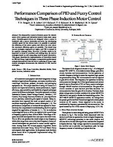
Figure 1: Cylinder position servo control diagram.
Combining the Coulomb friction and external load as 𝐹 and linearizing the force equilibrium equation, we can get 𝐴 1 𝑝1 − 𝐴 2 𝑝2 = 𝑚𝑠2 𝑦 + 𝑏𝑠𝑒 + 𝐹.
(7)
From the above analysis, the cylinder position servo control diagram can be drawn as Figure 1. If 0 ≤ 𝑢 < 5, then 𝑝1 =
3. Mathematic Model of the Pneumatic Position Servo System From the above dynamic characteristics basical equations, it is clear that the system is nonlinear. So we linearize the system near the cylinder equilibrium point based on the linear system theory. Generally, the spool opening area of proportional servo valve can be taken as the linear function of the controlling voltage; that is, the spool displacement is directly proportional to the controlling signal: 𝐴 𝑒 = 𝑘𝑎 𝑢,
(8)
where 𝑘𝑎 is the voltage proportional coefficient. Linearizing the flow equation of the proportional valve and applying the Laplace transform, we can get 𝑄𝑚1 = 𝐾𝑞1 𝑢 − 𝐾𝑝1 𝑝1 , 𝑄𝑚2 = 𝐾𝑞2 𝑢 − 𝐾𝑝2 𝑝2 ,
(9)
where 𝐾𝑞1 and 𝐾𝑞2 are the flow gains at the working point of the controlling valves for the cylinder chambers, 𝐾𝑞 = 𝜕𝑞𝑚 /𝜕𝑈; 𝐾𝑝1 and 𝐾𝑝2 are the flow pressure coefficients of the controlling valves for the cylinder chambers, 𝐾𝑃 = 𝜕𝑞𝑚 /𝜕𝑝. Linearizing the pressure differential equations of the cylinder chambers (2) and applying the Laplace transform, we can get 𝑝1 =
𝑘𝑅𝑇𝑞𝑚1 1 𝑘𝑝𝑘1 𝐴 1 𝑒, − 𝑉𝑘1 𝑠 𝑉𝑘1
𝑘𝑅𝑇𝑞𝑚2 1 𝑘𝑝𝑘2 𝐴 2 𝑒. 𝑝2 = − 𝑉𝑘2 𝑠 𝑉𝑘2
(10)
The force equilibrium equation (6) can be transformed as 𝐴 1 𝑝1 − 𝐴 2 𝑝2 = 𝑚𝑠2 𝑦 + 𝑏𝑠𝑦 + 𝑓𝑒.
(11)
𝑘𝑅𝑇𝐾𝑞1 𝑢 𝑉𝑘1 𝑠 + 𝑘𝑅𝑇𝐾𝑝1
−
𝑘𝑝𝑘1 𝐴 1 𝑒𝑠 , 𝑉𝑘1 𝑠 + 𝑘𝑅𝑇𝐾𝑝1
𝑘𝑝𝑘2 𝐴 2 𝑒𝑠 . 𝑝2 = − 𝑉𝑘2 𝑠 + 𝑘𝑅𝑇𝐾𝑝2
(12)
Substituting the above equations into (11) produces 𝑒=
(𝑉𝑘2 𝑠 + 𝑘𝑅𝑇𝐾𝑝2 ) 𝐴 1 𝑘𝑅𝑇𝐾𝑞1 𝑢 𝐶
,
(13)
where 𝐶 = 𝑚𝑉𝑘1 𝑉𝑘2 𝑠4 + (𝑚𝑉𝑘1 𝑘𝑅𝑇𝐾𝑝2 + 𝑚𝑉𝑘2 𝑘𝑅𝑇𝐾𝑝1 + 𝑏𝑉𝑘1 𝑉𝑘2 ) 𝑠3 + (𝑚𝑘2 𝑅2 𝑇2 𝐾𝑝2 𝐾𝑝1 + 𝑏𝑉𝑘1 𝑘𝑅𝑇𝐾𝑝2 + 𝑏𝑉𝑘2 𝑘𝑅𝑇𝐾𝑝1 ) 𝑠2 + (𝑓𝑉𝑘1 𝑉𝑘2 + 𝑘𝑝𝑘1 𝐴21 𝑉𝑘2 + 𝑘𝑝𝑘2 𝐴22 𝑉𝑘1 ) 𝑠2 + (𝑏𝑘2 𝑅2 𝑇2 𝐾𝑝1 𝐾𝑝2 + 𝑓𝑉𝑘1 𝑘𝑅𝑇𝐾𝑝2 + 𝑓𝑉𝑘2 𝑘𝑅𝑇𝐾𝑝1 ) 𝑠 + (𝑘2 𝑝𝑘1 𝐴21 𝑅𝑇𝐾𝑝2 + 𝑘2 𝑝𝑘2 𝐴22 𝑅𝑇𝐾𝑝1 ) 𝑠. (14)
4. Fuzzy PID Control Algorithm PID algorithm is the most used and useful control technique in mechatronics system. But the classical PID algorithm has its inherent shortcomings in practice because of the fixed parameters. For example, the fixed parameters cannot take into account the dynamic features and control requirements in both transient process and stable period. It often fails to achieve the ideal integrated control quality. So, in practice, PID algorithm is usually combined with other parameter adjusting methods, such as fuzzy logic and artificial neuro network.
4
Journal of Applied Mathematics 1
Feedback
−
KI
r(t)
NM
NS
ZO
PS
PM
−0.8
−0.4
0
0.4
0.8
PB
0.8
KP
+
NB
+
+
System u(t) model
0.6 y(t)
+
0.4
KD −1
0.2
ec(t) Fuzzy logic e(t)
0 −1.2
Figure 2: Fuzzy PID control principle.
1.2
Figure 3: Membership function for Δ𝐾𝑃 .
We integrate the classical PID algorithm and fuzzy logic, using fuzzy logic to adjust the PID control parameters according to the deviation and its gradient between the output and target. Thus we can control the cylinder position precisely. The basical control principle is shown in Figure 2. 4.1. Fuzzy Variables and Their Domain. The PID control input is 𝑒 (𝑡) = 𝑟 (𝑡) − 𝑦 (𝑡) .
(15)
And the output of the control module can be written as 𝑢 (𝑡) = 𝐾𝑃 𝑒 (𝑡) + 𝐾𝐼 ∫ 𝑒 (𝑡) d𝑡 + 𝐾𝐷
d𝑒 (𝑡) . d𝑡
Table 1: Fuzzy logic rule for Δ𝐾𝑃 . 𝑒𝑐 NB NM NS ZO PS PM PB
NB PB PB PB PM PM PS PS
NM PB PB PM PM PS PS ZO
NS PB PM PM PB PS ZO ZO
𝑒 ZO PM PM PS PS ZO ZO NM
PS PS PS PS PS ZO NS NS
PM PS ZO ZO ZO NS NM NB
PB ZO NS NS NM NM NB NB
PM NS ZO PS PM PM PM PM
PB ZO ZO PS PM PB PB PB
(16)
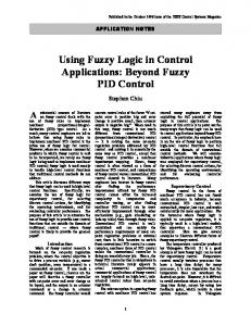
The deviation 𝑒(dis0 − dis) between the target position dis0 and the actual displacement dis of the cylinder and its gradient 𝑒𝑐(d𝑒/d𝑡) are the input variables for fuzzy logic. And the variations Δ𝐾𝑃 , Δ𝐾𝐼 , and Δ𝐾𝐷 of PID control parameters 𝐾𝑃 , 𝐾𝐼 , and 𝐾𝐷 are the output variables of the fuzzy logic. The cylinder position deviation 𝑒 and its gradient 𝑒𝑐 are sampled and calculated in real time. And the output variables Δ𝐾𝑃 , Δ𝐾𝐼 , and Δ𝐾𝐷 are extracted from the fuzzy matrix table based on the fuzzy rules and reasoning. The PID control parameters are adjusted using Δ𝐾𝑃 , Δ𝐾𝐼 , and Δ𝐾𝐷, in order to realize the real-time dynamic control of the cylinder displacement. According to the cylinder position control requirement, the domain of the displacement deviation 𝑒 is set as (−0.5, 0.5), and the domain of the 𝑒𝑐 is (−0.1, 0.1). The domains of Δ𝐾𝑃 , Δ𝐾𝐼 , and Δ𝐾𝐷 for PID parameters are (−1.2, 1.2), (−0.1, 0.1), and (−0.05, 0.05), respectively. 4.2. Fuzzy Logic Rules. The triangle membership function is adopted, and the membership function for Δ𝐾𝑃 is shown in Figure 3. The fuzzy logic rules are deduced, as listed in Tables 1, 2, and 3. In these tables, NB, NM, NS, ZO, PS, PM, PB represent negative big, negative medium, negative small, zero, positive small, positive medium, and positive big, respectively.
Table 2: Fuzzy logic rule for Δ𝐾𝐼 . 𝑒𝑐 NB NM NS ZO PS PM PB
NB NB NB NB NM NM ZO ZO
NM NB NM NM NM NS ZO ZO
NS NM NM NS NS ZO PS PS
𝑒 ZO NM NS ZO ZO PS PS PM
PS NS NS ZO PS PS PM PM
Using the above fuzzy logic rules, the PID control parameters can be adjusted as
𝐾𝑃(𝑛+1) = 𝐾𝑃𝑛 + Δ𝐾𝑃 , 𝐾𝐼(𝑛+1) = 𝐾𝐼𝑛 + Δ𝐾𝐼 , 𝐾𝐷(𝑛+1) = 𝐾𝐷𝑛 + Δ𝐾𝐷.
(17)
Journal of Applied Mathematics
5
Table 3: Fuzzy logic rule for Δ𝐾𝐷 . ec NB NM NS ZO PS PM PB
NB PS PS ZO ZO ZO PS PB
NM NS NB NS NS PM PB PM
NS NB NB NM NS PS PS PM
e ZO NB NM NM NS ZO PS PS
PS NM NM NS NS ZO PB PB
r(nT)
PM NM NS NS ZO PS PB PS
PB PS ZO ZO NS ZO PS PS
Define 𝑅𝑙 = (𝑒 and 𝑒𝑐) → 𝐾𝑃 =∫
𝑒×𝑒𝑐×𝐾𝑃
𝑢 (𝑒) Λ𝑢 (𝑒𝑐) Λ𝑢 (𝐾𝑃𝑛 ) , 2
𝑅𝑚 = (𝑒 and 𝑒𝑐) → 𝐾𝐼 =∫
𝑒×𝑒𝑐×𝐾𝐼
𝑢 (𝑒) Λ𝑢 (𝑒𝑐) Λ𝑢 (𝐾𝐼𝑛 ) , 2
(18)
𝑅𝑛 = (𝑒 and 𝑒𝑐) → 𝐾𝐷 =∫
𝑒×𝑒𝑐×𝐾𝐷
𝑢 (𝑒) Λ𝑢 (𝑒𝑐) Λ𝑢 (𝐾𝐷𝑛 ) , 2
where 𝑙, 𝑚, 𝑛 = 1, 2, 3, . . . , 25. Then the fuzzy relations of 𝐾𝑃 , 𝐾𝐼 , and 𝐾𝐷 are 25
𝑅𝐾𝑃 = ⋃𝑅𝑙 , 𝑙=1
25
𝑅𝐾𝐼 = ⋃ 𝑅𝑚 ,
(19)
𝑚=1 25
𝑅𝐾𝐷 = ⋃ 𝑅𝑛 . 4.3. Defuzzification. The outputs of the fuzzy logic rules are also fuzzy set. In practical digital control system, the parameters must be defuzzified, that is, converting the fuzzy set into exact values according to an appropriate algorithm. We use conventional gravity center method to realize the defuzzification: 𝑦 =
∫𝑌 𝑦𝑢𝑐 (𝑦) d𝑦 ∫𝑌 𝑢𝑐 (𝑦) d𝑦
Fuzzy
u(nT) System model
+
PI
−
y(nT)
+ −1 ec(nT)
Fuzzy D
Figure 4: Discrete-time Fuzzy PID controller.
4.4. Stability Analysis. Chen and Ying [10] theoretically proved the stability of nonlinear fuzzy PI controller, based on their previous work on fuzzy control theory [11]. After that, they continued to investigate the stability of nonlinear fuzzy PI + 𝐷 controller [12]. Their work offers a quite convenient and practical method to explore the stability of similar control algorithms. As described in Section 2, the target cylinder system can be taken as a classical second order system. To interpret the stability of the proposed nonlinear system, we need to reconsider the fuzzy PID control principle shown in Figure 2, which can be rearranged as Figure 4 in discrete-time form, where 𝑇 is the sampling period, 𝑇 > 0. This diagram expresses the same meaning as Figure 2 and shows the simplified structure as a figure in [12]. The stability of the fuzzy PI controller and the fuzzy PD controller has been analyzed in [10, 13], respectively, according to the small gain theorem [14]. In our case, if we disconnect the fuzzy 𝐷 control component from Figure 4, we have the fuzzy PI control system, whose stability is completely proved in [10]. The stability conditions are as follows. Theorem 1. A sufficient condition for the nonlinear fuzzy PI control system to be globally bounded-input and boundedoutput (BIBO) stable is that (1) the given nonlinear system has a bounded norm (gain) ‖𝑁‖ < ∞;
𝑛=1
∗
+
e(nT)
,
(20)
where 𝑦∗ is the center of the covered region by membership function 𝑢𝑐 (𝑦) of fuzzy set 𝐶. It is obvious that the calculating process needs certain time, which makes it difficult to be used in real-time control system. So, the calculating process is executed off-line in advance. Then the produced defuzzification decision tables are stored in the memory of the controller. In this way, the instantaneity of the control process can be enhanced.
(2) the parameters of the fuzzy PI controller 𝐾𝑃 , 𝐾𝐼 , and 𝐾𝑢𝑃𝐼 satisfy 𝐾𝑢𝑃𝐼 (𝛾𝐾𝑃 + 𝐾𝐼 ) 𝐿 ‖𝑁‖ < 1, 𝑇 (2𝐿 − 𝐾𝑀)
(21)
where 𝐿 is the domain boundary of fuzzy logic parameters, 𝛾 = max{1, 𝑇} and 𝐾𝑀 = max{𝐾𝑃 𝑀𝑃 , 𝐾𝐼 𝑀𝑐 }, with 𝑀𝑃 = sup𝑛≥0 |𝑒(𝑛𝑇)| and 𝑀𝑐 = sup𝑛≥0 |𝑒𝑐(𝑛𝑇)| ≤ (2/𝑇)𝑀𝑃 . In the same way, by disconnecting the fuzzy PI controller from Figure 4, we reduce the fuzzy PID control system to a simple fuzzy 𝐷 controller. This fuzzy 𝐷 control system is a special or simplified case of the fuzzy PD control system studied in [13], and hence its stability condition can be derived from that obtained in [13] by removing the fuzzy 𝑃 controller or just setting the output of fuzzy 𝑃 component as zero. The stability conditions can be derived as follows.
6
Journal of Applied Mathematics
0
u
y
System model
+ +
− +
Fuzzy D +
0
u
y
S1
+
ec
+ −1
−
Fuzzy PI
r
+
e
− e
S2 (a) Another form of the fuzzy PID controller
r
+
(b) Equivalent structure of the controller
Figure 5: Equivalent closed-loop control system for the fuzzy PID controller.
Theorem 2. A sufficient condition for the fuzzy 𝐷 control system to be BIBO stable is that the given process has a bounded norm (gain) ‖𝑁‖ < ∞ and the parameters of the fuzzy 𝐷 controller 𝐾𝐷 and 𝐾𝑢𝐷 satisfy 𝛾𝐾𝐷𝐾𝑢𝐷 ‖𝑁‖ < 1, 2𝑇 (𝐿 − 𝐾𝐷 (𝑀𝐷 + |𝑟|))
Displacement transducer
Flow proportional valve Pressure transducer Main cylinder
(22)
Viscous cylinder
where 𝛾 = max{1, 𝐿}. Till now, we are sure that the fuzzy PI controller and fuzzy 𝐷 controller are stable according to Theorems 1 and 2, respectively. Then, we need to verify that the combined fuzzy PID controller is stable. Again, the Fuzzy PID controller shown in Figure 2 can be redrawn as Figure 5. The fuzzy PID control systems shown in Figures 2, 4, and 5 are the same thing but in different forms, just for analysis convenience. In Figure 5(a), let the system model be denoted by 𝑆1 and the fuzzy PID controller together be denoted by 𝑆2 , resulting in the new structure in Figure 5(b). Then, as discussed in [10, 13], we can obtain a sufficient condition for the BIBO stability of the overall fuzzy PID equivalent closed-loop control system from the bounds: 𝑆1 (𝑢PID ) ≤ 𝑀1 + 𝐿 1 𝑢PID , (23) 𝑦 𝑦 𝑆2 ([ ]) ≤ 𝑀2 + 𝐿 2 [ ] , 𝑒 𝑒 where 𝑀1 , 𝑀2 , 𝐿 1 , 𝐿 2 are constants, and 𝐿 1 𝐿 2 < 1.
5. Experiments and Analysis 5.1. Experimental System Design. The experimental system is composed of pneumatic servo control actuating mechanism, feedback units, loading module, and controller. The pneumatic servo control actuating mechanism is symmetrical cylinder system controlled by proportional flow valve. The feedback units include displacement transducer and the pressure
Elastic load
Fore transducer Mass load
A/D
IPC
Force cylinder Pressure proportional valve
D/A
Figure 6: Pneumatic servo control system principle.
transducer for the cylinder chambers. The whole controller for the system includes industrial personal computer (shorted as IPC), A/D, and D/A board cards for data acquisition and output. The experimental system schematic diagram is shown in Figure 6 and the experimental platform is shown in Figure 7. The instruments used in the experiment are listed in Table 4. The control software was developed based on MATLAB and LabVIEW. All the fuzzy logic and PID control algorithms were realized in MATLAB simulink toolbox and then compiled into real-time control program using RTW technique.
Journal of Applied Mathematics
7 Table 4: Experimental instruments.
Name
Model
Specification
Brand
Main cylinder Flow proportional valve Pressure proportional valve
CA2WL40-500 MPYE-5-1/8-010B MPPE-5-1/8-010B
SMC Festo Festo
Displacement transducer
MTS-500
Pressure transducer
JYB-KO-HVG
Force transducer
BK-1
Φ32 mm, range: 500 mm Max flow: 700 L/min, response: 3 ms, lag: 0.3% Max flow: 820 L/min, response: 3 ms, lag: 0.3% Range: 500 mm, resolution: 5 us, repeatability: ±0.001% FS Accuracy: 0.25% FS, range: 0-1 Mpa, response: 30 ms, nonlinearity: ±0.2% FS, repeatability: ±0.1% FS Range: 1500 N, accuracy: 0.05% FS, nonlinearity: 0.05% FS, repeatability: 0.05% FS
MTS Kunlun Coast Kunlun Coast
Model and simulation
Analysis in MATLAB
Monitor and adjustment
Generate C codes
Real-time test environment
Figure 8: Working flow with RTW.
Table 5: Control errors of cylinder position (mm). Figure 7: Experimental system.
RTW is an important supplementary functional module for MATLAB graphic modeling and simulation module Simulink. Optimized, portable, and personalized codes can be directly generated from Simulink model with RTW tools. According to the specific target preparation, the generated codes can be compiled into program for a different rapid prototype real-time environment. RTW ensures us to focus on the model establishment and system design and release from the boring programming work. This kind of developing pattern is very suitable for laboratory experimental system design. RTW technique has the following features: (1) it supports continuous, discrete, and hybrid time system, including conditioned executing system and nonvirtual system; (2) RTW seamlessly integrates the Run-Time Monitor with the realtime target, which provides an excellent signal monitor and parameters adjusting interface. The flow diagram of real-time control program developing using RTW technique is shown in Figure 8. LabWindows/CVI is adopted to create the control program frame and user interface, shown in Figure 9. 5.2. Target Position Control Experiments. On the experimental platform, we set the target position of the cylinder as 250 mm, 300 mm, and 350 mm, respectively. And the control results are shown in Figures 10, 11, and 12. The rising times of the three experiments are 2.65 s, 4.3 s, and 3.2 s, respectively, which indicates that long displacement
Initial 100 100 100
Target 250 300 350
AE 0.2441 0.20 0.2441
RE 0.20% 0.07% 0.09%
AE represents absolute error and RE denotes relative error.
does not mean long corresponding time. During the motion, the proposed fuzzy PID controller can adjust the control parameters and change the behavior of the system to achieve the best performance. Also, the overshoots in Figures 10, 11, and 12 are 0.49 mm, 0.04 mm, and 0 mm, respectively. Consulting the stable errors listed in Table 5, we can see that when the displacement becomes longer, the system hysteresis shows greater influence on the final error. To be more frank, long displacement has no overshoot but big negative error, while short displacement has big overshoot and positive error. From the experimental data, three significant features can be drawn as follows. (1) Dynamic quality: the proposed method has fuzzy logic virtues in the earlier stage of control that can actuate the cylinder to approximate the target position rapidly. And during the late stages of control, it has virtues of PID algorithm, which means that the PID parameters are adjusted to execute the cylinder to quickly reach the target position without overshoot. (2) Stable quality: the analysis of stable error is listed in Table 5. From the error analysis, it can be seen that the proposed theoretical model, control method, and experimental system can guarantee that the absolute
8
Journal of Applied Mathematics
Figure 9: LabVIEW control program diagram.
260
350
Cylinder displacement d (mm)
Cylinder displacement d (mm)
240 220 200 180 160 140
300
250
200
150
120 100
100 0
1
2
3
4
5
0
1
control error is around 0.24 mm. In addition, the error is independent of the target position. The robust of the control method is quite well. (3) No creeping phenomenon: when the cylinder runs with quite low speed or stops in the middle, there will be creeping phenomenon because of the air pressure in both the chambers and friction. From the response data in Figures 10, 11, and 12, it can be concluded that the proposed method can control the cylinder to stay at any position without creeping phenomenon. 5.3. Compared with Classical PID. To show the advantages of the proposed cylinder position servo control method, an experiment was done to compare the classical PID controller and the developed one in this paper, with the target position 300 mm.
3
4
5
6
Time t (s)
Time t (s)
Figure 10: Response of target position 250 mm.
2
Figure 11: Response of target position 300 mm.
The stable state data and error data are shown in Figures 13 and 14. From the above two comparing data curves, it can be seen that the classical PID controller can achieve the destination, but has bigger error, error range, and overshoot, which are 0.78 mm, 0.25 mm, and 0.78 mm, respectively. However, the proposed fuzzy PID controller has relative smaller error, error range, and overshoot, which are 0.20 mm, 0.24 mm, and 0.04 mm, respectively.
6. Conclusions (1) The nonlinear mathematical models of cylinder and its valve-control pneumatic system, that is, pressure differential equation, pressure-flow equation, and moment equilibrium equation, are proposed. (2) The cylinder position servo controller based on the mathematical models and fuzzy PID algorithm is
Journal of Applied Mathematics
9
350
1
Displacement error e (mm)
Cylinder displacement d (mm)
0.8 300
250
200
150
0.6 0.4 0.2 0 −0.2 −0.4
100
0
1
2
3
4
5
−0.6 4.5
5
5.5
Time t (s)
Time t (s)
PID Fuzzy PID
Figure 12: Response of target position 350 mm.
Figure 14: Error of comparing experiment.
Cylinder displacement d (mm)
301
Acknowledgments 300.5
This work is financially supported by the National Natural Science Fund of China (Grant no. 51275470), the open fund of Key Laboratory of E&M (Zhejiang University of Technology), Ministry of Education & Zhejiang Province (Grant no. 2011EM001), and fund of Zhejiang Educational Department (Grant no. Y201225592).
300
299.5
References 299 4.5
5 Time t (s)
5.5
PID Fuzzy PID
Figure 13: Stable data of comparing experiment.
established and proved to be stable under specified conditions. (3) Experimental results show that the absolute control error is less than 0.25 mm and the proposed fuzzy PID controller has better performance than classical PID. The dynamic and stable qualities of the controller are quite well.
Conflict of Interests The authors wish to confirm that there is no known conflict of interests associated with this paper and there is no conflict of interests for any of the authors.
[1] J. L. Shearer, “Study of pneumatic processes in the continuous control of motion with compressed air,” Transactions of the ASME, vol. 2, pp. 233–242, 1956. [2] S. Scavanda, A. Kellal, and E. Richard, “Linearized models for an electropneumatic cylinder servo valve system,” in Proceedings of the 3rd International Conference in Advanced Robotics, pp. 13–15, Versailles, France, 1987. [3] S. Liu and J. E. Bobrow, “Analysis of a pneumatic servo system and its application to a computer-controlled robot,” Journal of Dynamic Systems, Measurement and Control, Transactions of the ASME, vol. 110, no. 3, pp. 228–235, 1988. [4] L. Baoren, Research on Digital Electronic/Pneumatic Pressure Control Valve and Electronic/Pneumatic Position Servo System, Harbin Institute of Technology, Harbin, China, 1995. [5] D. Yunbo, Research on Pneumatic PWM Position Servo System, Harbin Institute of Technology, 1995. [6] T. Guoliang, M. Wenjie, and W. Xuanyin, “Lab research for mechanism modeling of pneumatic servo system,” Hydraulics Pneumatics and Seals, vol. 10, pp. 26–31, 1999. [7] B. Wei, T. Guoliang, L. Bo, M. Deyuan, and Y. Yuefeng, “Modeling and characteristics investigation on a new pneumatic proportional pressure valve,” Journal of Zhejiang University, vol. 46, no. 11, pp. 1953–1959, 2012. [8] H. K. Lee, G. S. Choi, and G. H. Choi, “A study on tracking position control of pneumatic actuators,” Mechatronics, vol. 12, no. 6, pp. 813–831, 2002.
10 [9] W. Haijiang, Design of Pneumatic System and Research on Its Position and Velocity Servo Control System, Xi’an Jiaotong University, 2004. [10] G. Chen and H. Ying, “Stability analysis of nonlinear fuzzy PI control systems,” in Proceedings of the 3rd International Conference on Fuzzy Logic Applications, pp. 128–133, Houston, Tex, USA, 1993. [11] H. Ying, W. Siler, and J. J. Buckley, “Fuzzy control theory: a nonlinear case,” Automatica, vol. 26, no. 3, pp. 513–520, 1990. [12] D. Misir, H. A. Malki, and G. Chen, “Design and analysis of a fuzzy proportional-integral-derivative controller,” Fuzzy Sets and Systems, vol. 79, no. 3, pp. 297–314, 1996. [13] H. A. Malki, H. Li, and G. Chen, “New design and stability analysis of fuzzy proportional-derivative control systems,” IEEE Transactions on Fuzzy Systems, vol. 2, no. 4, pp. 245–254, 1994. [14] R. J. P. de Figueiredo and G. R. Chen, Nonlinear Feedback Control Systems: An Operator Theory Approach, Academic Press, New York, NY, USA, 1993.
Journal of Applied Mathematics
Advances in
Operations Research Hindawi Publishing Corporation http://www.hindawi.com
Volume 2014
Advances in
Decision Sciences Hindawi Publishing Corporation http://www.hindawi.com
Volume 2014
Journal of
Applied Mathematics
Algebra
Hindawi Publishing Corporation http://www.hindawi.com
Hindawi Publishing Corporation http://www.hindawi.com
Volume 2014
Journal of
Probability and Statistics Volume 2014
The Scientific World Journal Hindawi Publishing Corporation http://www.hindawi.com
Hindawi Publishing Corporation http://www.hindawi.com
Volume 2014
International Journal of
Differential Equations Hindawi Publishing Corporation http://www.hindawi.com
Volume 2014
Volume 2014
Submit your manuscripts at http://www.hindawi.com International Journal of
Advances in
Combinatorics Hindawi Publishing Corporation http://www.hindawi.com
Mathematical Physics Hindawi Publishing Corporation http://www.hindawi.com
Volume 2014
Journal of
Complex Analysis Hindawi Publishing Corporation http://www.hindawi.com
Volume 2014
International Journal of Mathematics and Mathematical Sciences
Mathematical Problems in Engineering
Journal of
Mathematics Hindawi Publishing Corporation http://www.hindawi.com
Volume 2014
Hindawi Publishing Corporation http://www.hindawi.com
Volume 2014
Volume 2014
Hindawi Publishing Corporation http://www.hindawi.com
Volume 2014
Discrete Mathematics
Journal of
Volume 2014
Hindawi Publishing Corporation http://www.hindawi.com
Discrete Dynamics in Nature and Society
Journal of
Function Spaces Hindawi Publishing Corporation http://www.hindawi.com
Abstract and Applied Analysis
Volume 2014
Hindawi Publishing Corporation http://www.hindawi.com
Volume 2014
Hindawi Publishing Corporation http://www.hindawi.com
Volume 2014
International Journal of
Journal of
Stochastic Analysis
Optimization
Hindawi Publishing Corporation http://www.hindawi.com
Hindawi Publishing Corporation http://www.hindawi.com
Volume 2014
Volume 2014