Dasor, a Discrete Events Simulation Library for Grid and Peer-to-Peer Simulators Cyril Rabat ABSTRACT. Simulation is a key point for designing applications for large scale systems like grids or peer-to-peer networks. To be relevant, a simulation must be computed with adequate models: communication models, fault models or network models (bandwidth, latency). In previous works, we proposed a five layers model to map grid applications and the subjacent network. Particularly, it shows how subjacent protocols can impact higher layers. Here, we describe a simulation library called Dasor based on this model. It is a C++ discrete events simulation library that allows to build simulators independently of the network and of the simulation models. So, a simulator can be executed on different environments like dynamical networks or wireless networks without any modification of the simulator code. The simulation granularity can also be modified easily. ´ ´ La simulation est un point clef pour la cr´eation d’applications destin´ees aux RESUM E. syst`emes d´eploy´es a` grande e´ chelle tels que les grilles ou les r´eseaux pair-`a-pair. Pour eˆ tre pertinentes, les simulations doivent eˆ tre r´ealis´ees avec des mod`eles appropri´es : des mod`eles de communication, de fautes ou de r´eseau (bande passante, latence). Dans des travaux pr´ec´edents, nous avons propos´e un mod`ele en 5 couches pour mapper des applications de grille ainsi que le r´eseau sous-jacent. En particulier, il montre comment les protocoles sous-jacents peuvent impacter les couches sup´erieures. Nous d´ecrivons ici une biblioth`eque de simulation appel´ee Dasor bas´ee sur ce mod`ele. C’est une biblioth`eque C++ pour la simulation a` e´ v´enements discrets qui permet de construire des simulateurs ind´ependamment du r´eseau et des mod`eles de simulation. Ainsi, un simulateur peut eˆ tre ex´ecut´e sur diff´erents environnements tels que des r´eseaux dynamiques ou des r´eseaux sans-fil sans aucune modification du code du simulateur. Le grain de la simulation peut ainsi eˆ tre modifi´e simplement. KEYWORDS: Discrete events simulation, Grid, Peer-to-peer ´ : Simulation a` e´ v´enements discrets, Grille, Pair-`a-pair MOTS-CLES
1. Introduction Designing distributed solutions for large scale systems like grids or peer-to-peer networks implies several challenges. First, it needs a theoretical model to define the system (network limitations, impacts of data localization or resource volatility). Several models have been already proposed and we can gather them in two categories : the models that focus on application architecture and the models that focus on material and resources. The authors of [LPP04] choose to model the network grid topology. This kind of model can highlight the bandwidth consumption and the network overload but it is independent of the grid application. In [BBL02], the authors propose a model based on the fabric notion. The components and the grid architecture are organized on several layers. But this model focuses on the grid and does not take into account subjacent protocols or mechanisms. So, in [RBF06], we propose a five layers model for grid applications that focuses both the application and the underlying protocols. Particularly, we are able to measure protocols impacts in higher layers. Figure 1 shows a simplified view of our model. The next step for an application development is the distributed algorithm design depending on the chosen model. Before the development of a final application, we can simulate the behavior of the distributed algorithms to observe their scalability or their fault tolerance. But it could be difficult to choose a suitable simulation tool and simulation models to apply. A number of simulation tools have already been proposed. But the simulation granularity is often hard to adapt. For instance, OMNeT++ [Var01] and Ns-2 [Ns-] have been designing for the oriented network applications. These solutions focus on the low-layer protocols and do not propose to simulate components of grid or peer-to-peer applications. Other tools like Narses [GB02] a peer-to-peer application simulator, are based on flow simulation instead of a packet management. The simulation computation time is reduced but the simulation granularity is high. The bottleneck problems cannot be simulated. Simulator
2
Application Services/Components Tasks
Resources localization
Monitoring
Etc...
management Grid Middleware
Resources management
Communications Network
Routing Physical
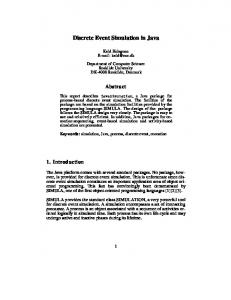
Figure 1: Theoretical model for grid applications designing. users1 often need to modify the granularity depending on the component tested and the previous tools cannot be easily used. In this article, Dasor is presented: this is a C++ library for discrete events simulation based on our model. It allows the user to interact at each layer of our model. So, a simulator user can choose the suited simulation granularity by selecting the simulation models. Because simulators developed with Dasor are designed independently of the network and the simulation models, this choice can be modified without changing the simulator code. The rest of the paper is organized as follows. Section 2 provides related works on simulation tools and a presentation of our theoretical model. Section 3 gives a description of the simulation library. First, a global description of Dasor is proposed. Then, the development of a simulator is described. Finally, the simulators execution model and the simulation models description are presented. In last section, we conclude and we present our future works. 1. In the following, a person who develops a simulator thanks to a simulation library is called a simulator developer and a person who uses a simulator is called a simulator user.
3
2. Preliminaries In this section, we present a state of the art of simulation tools and we describe the theoretical model we propose in [RBF06] to model a grid or a peer-to-peer application. 2.1. State of the art 2.1.1. Network simulation tools In most cases, the grid resources are deployed in several interconnected local networks. Local networks interactions may have an impact on the grid performances, decreasing its efficiency for example. When the communications are critical (for example if a lot of data is exchanged between nodes), it is necessary to focus on the physical network view to improve the grid application efficiency. OMNeT++ [Var01] is a discrete events simulation library written in C++. It aims to simulate communication networks. An OMNeT++ simulator is based on modules that communicate by message passing. To represent a network, each node can be composed of a modules stack. So, when a message is sent between two nodes, it is transparently transfered through each subjacent module. This behavior allows to simulate a protocol stack like the TCP/IP one. The network structure is described thanks to a specific file written in NED language. From this file, a compilation tool generates C++ classes of the simulator that the developer has to modify. Ns-2 [Ns-] also proposes to simulate network protocols. It allows to create and to test new protocols or can be used to compare similar protocols. It is based on OTcl scripts to describe the events or to build a network by specifying the bandwidth of each link. It is possible to select a routing protocol, a transport protocol (TCP, UDP) or application protocol (FTP, Telnet). These tools are used to study the network protocols. They can also be used to simulate distributed applications. But the specific needs of grids are not taken into account. So, dedicated tools have been proposed.
4
2.1.2. Grid simulation tools A grid middleware can be viewed as a set of components like a resources manager or a tasks manager. During the middleware designing, we have to check the compatibility of such components and the communications impacts between these components. Several tools have been developed for the specific needs of grids. SimGrid [LMC03] is a C library to build discrete events simulators. These simulators gathers 5 elements: 1) the agents are in charge of the scheduling, 2) the locations are the places in the topology where agents are executed, 3) the tasks are either computations or data transfers, 4) the paths correspond to the paths between locations and gather communication resources, 5) the channels symbolize a communication between agents. SimGrid allows specific functionalities for the tasks management with the management of tasks dependencies. The Java package OptorSim [BCC+ 02] is dedicated to the data grid simulation. During a simulation, each node of the grid gives computation and storage capabilities that can be used for task computation. A replica manager is in charge of the transfer and the duplication of data between nodes. This manager can be modified by the developer, so it is possible to compare several strategies of data replication. MicroGrid tool [LXC04] aims to emulate virtual grids. Contrary to the previous tools, it provides to an existing application a virtual grid. The application is transparently executed over this grid. It is be possible to study the behaviors of the application in function of the grid parameters (number of nodes, network properties). Other libraries like GridG [LD03] allow to create realistic grid topologies based on Internet. These topologies can be used in other simulation tools. 2.2. A model for grid and peer-to-peer applications In [RBF06], we have proposed a model based on 5 layers for grid or peer-to-peer applications. This model is represented on Figure 1. It is used to model the subjacent network of a grid that interacts independently of the grid middleware. It also models the components of the grid middleware and interactions between them.
5
2.2.1. Physical network layer The first layer concerns the physical network. The network is represented by a graph G1 = (V1 , E1 ). V1 is the network nodes set. A node can be an active component (like a desktop computer, a server or a parallel machine), or a passive component (like a router, a switch or a modem). E1 is the set of links that interconnect the network nodes. We distinguish two kinds of links: a physical wire and a wireless connection. The physical wires are naturally undirected. But with the wireless connections, we have to take care of the different emission ranges of the network nodes. If a node has a higher range than another one, this induces a directed link in E1 .
8
6
6
7
8
5
5 7 4
9
9
2
3
4
1
2
3
1
Figure 2: Example of a network representation in Layer 1. Example 2.1 Figure 2 shows an example of a network (left figure) represented in the first layer of the model (right figure). The nodes (1 to 7) are connected with wired connections: the links in the corresponding graph are undirected. For the two wireless nodes, we can remark that Node 9 has a higher range that Node 8 (ranges are represented by a circle on the figure). We obtain a directed link in E1 . 2.2.2. Routing layer Over the physical network, a routing protocol builds and maintains paths between the nodes of the network. Two entities can communicate even if they are not directly physically connected. The paths construction takes into account the several security policies deployed over subnetworks (firewalls). In the same way, some protocols (like NAT)
6
can limit the access to nodes. For these reasons, directed communication links are considered. In Layer 2, the network is represented by the graph G2 = (V2 , E2 ), where V2 = V1 and E2 is the set of paths between nodes of V2 . Example 2.2 Figure 3 is based on the example of Figure 2 and shows the representation of the network in Layer 2. To simplify, the paths that start or end from passive components (Nodes 4, 5 and 7) are not displayed. We remark new links that represent the paths computed by the routing protocol. For the wireless entities (Nodes 8 and 9), we remark that the directed link (9, 8) has been deleted: Node 8 can contact Node 9 through Node 7. 8
8
6
7
9
7
5
9
4
1
2
6
3
5
4
1
2
3
Figure 3: Example of a network representation in Layer 2.
2.2.3. Communication layer Over the paths built from the subjacent layer, it is possible to send data between two distant nodes that are not physically connected. The network is represented as a graph G3 = G2 . In this layer, we can have the message send and receive capabilities thanks to a given protocol or a protocols stack. Several mechanisms can be proposed to manage communication problems (loss or duplication of messages, data corruption). An acknowledgment mechanism can ensure that a sent message has been received. If a message is lost, it is sent again. Another mechanism can ensure the message integrity.
7
2.2.4. Topology layer The two higher layers focus on the grid middleware. Layer 4 is the resources management layer that can be viewed as an interface between the components and the services of the grid and the subjacent layers. In this layer, we distinguish two kinds of nodes. The first ones, called the active nodes, are within the grid. These nodes share their own resources or use the grid resources. The others ones, the passive nodes are outside the grid such as routers or switches. In this layer, the grid is represented as a graph G4 = (V4 , E4 ) where V4 is the set of active nodes and E4 is the set of communication links between active nodes. In this layer, the passive nodes are not represented in the graph (cf Figure 4). But they can influence the efficiency of the grid application (due to network overloads). So, it is the reason why we propose a several layers model. 8
8
6
7
9
5
9
4
1
6
2
3
1
2
3
Figure 4: Example of a grid representation in Layer 4. 2.2.5. Grid components and services layer The last layer concerns the grid components and services including the tasks management and the resources monitoring service. The deployed components depend on the middleware: if it concerns the file sharing, it must have a component to transfer the files and maybe a component to manage access rights and queues for users. The grid is represented by the graph G5 = (V5 , E5 ) where V5 = V4 and E5 is the set of communication links proposed by the topology layer. E5 is not equal to E4 : it depends on the protocol that manages the grid topology or the peer-to-peer overlay network.
8
Example 2.3 For the middleware CONFIIT [FKF03], a computational peer-to-peer middleware, nodes are setup into a virtual ring in which tokens circulate (one for the topology management and one for the tasks management). Connections are established between the neighbors in the virtual ring. To be fault tolerant, a k-tolerance mechanism has been proposed: connections can be established with the k next neighbors in the ring. In CONFIIT, E5 contains only undirected links which are the links of the virtual ring and the links related to the k-tolerance mechanism (cf figure 5 a). For Gnutella [Gnu], connections are established between neighbors in the grid, the neighborhoods are randomly built among the connected peers. The established connections are used to transfer the protocol messages (control and user requests). For a file transfer, a new connection is established between the file requester and the peer that owns the file. The connection is established by the file requester. But if the peer that owns the file is protected behind a firewall, the establishment of the connection can be impossible. Gnutella protocol proposes another message to ask the peer that owns the file to establish the connection. So, in the case of Gnutella, E5 contains both directed and undirected links (cf figure 5 c). 8
8
6
9
8
6
9
1
2
(a)
3
6
9
1
2
(b)
3
1
2
3
(c)
Figure 5: Example of grid representations in Layer 5. This model highlights the impacts of protocols that interact under a grid. We can focus on a specific layer or a component. For example, the resources management (Layer 4) has already been focused in [RBF06, BBFR06] and tasks management in [BFR07].
9
3. Dasor Dasor [DAS] is a C++ library for discrete events simulation of grid and peer-to-peer applications. The aim of Dasor is to develop simulators independently of the network and the simulation models applied at the execution. Indeed, the network and the models are only specified at the execution thanks to a network description file. The file syntax easily describes complex topologies and predefined models. 3.1. Description of the library content Dasor is used to build independent simulators that need some files at the execution: a configuration file (.ini) containing general options like the number of simulations or the simulation maximal time, a description file (.net) describing the network and the simulation models used (see next section) and eventually some data files (for resources description like tasks, files or libraries). A simulator can execute series of simulations and provides an output description file (.des) containing information about the simulation execution and a statistics file (.sta) containing registered values (more details on these files given in Section 3.6). The execution model of a simulator developed with Dasor is based on the theoretical model as shown in Figure 6. Each simulation model is considered as a component of a theoretical model layer2 . The selected simulation models are managed from the lower layer to the upper layers. A simulator is written independently of them and they are specified thanks to the input description file. By default, several models are applied and it is not necessary for the simulator user to specify the simulation models for each layer of the theoretical model. So, it is possible to modify the simulation granularity by selecting or ignoring some models. For instance, the description of a link between two nodes in the input description file can be either a physical link when a routing model is specified or a communication link without routing simulation model (by default, no routing model is applied). The simulation granularity can also be adjusted according to the applied models. Some routing models simulate the packet 2. If some models are not specified, simulation models can overlap several layers.
10
grid components
Topology
Network Routing Comm.
User algorithms Simulator components
Resources manager
Communication protocol (messages loss, duplication, corruption)
Routing protocol (computation of communication links)
Network topology
Failure model (link or node disconnection)
Communication model
Mobility model
(bandwidth)
(node mobility)
Figure 6: Execution model of simulators developed with Dasor based on our theoretical model. exchanges whereas some models compute globally (in a centralized way) the paths between nodes. The computational power needed to execute simulation can be reduced but with a higher simulation grain. GNU Scientific Library [GDT+ 06] (GSL) has been integrated to Dasor for the random numbers generation. We propose interfaces to use the random number generators as tools to develop simulators. They can aslo be used in the input description file to configure simulation models. When a simulation model needs an integer or a real as a parameter, it is possible to specify a random number generator. The Dasor Toolbox is a set of tools provided with the library. For instance, makeSimu assists in the creation of new simulators and makeDiag builds execution diagrams from output simulator files to show the tasks computations, the nodes failures or the messages exchanges. It also provides some statistics about the produced events during the simulator execution. convertNet tool supports the conversion of a input description file to a postscript file and can also be used to create a new input description file by removing random events of specified simula-
11
tion models. Then, such files can be used to test the reproducibility of results. 3.2. Input description file An input description file contains the network description and the simulation models applied on the execution model. First, the number of nodes and global options must be specified: the network can be wired or wireless, the links can be directed or not and weighted or not (used to simulate distributed algorithms). For a wired network, the syntax of the network files allows to describe simple topologies (like directed or undirected rings, stars, grids, chains or trees) or more complicated topologies (like random networks, directed of undirected degree-constant networks, hierarchical caveman [Wat99] and small worlds). Links can be described one by one or with a full adjacency matrix. For wireless networks, links can be ignored and computed from nodes positions. Predefined position models can be used (like circle, random, grid or fixed density) and links will be computed during simulation depending on the node positions and the chosen communication model. Description files also describe the models used during the simulation. Particularly, we can choose between several fault models, routing protocols, communication models or mobility models. By default, no fault model or mobility model are applied on the network and a default communication model is selected. Each model can be configured by specifying options. The periodical fault model involves that each node fails periodically. This model needs as parameter both the interval for the faults lengths and the interval for the alive lengths. The simulator user can describe simple events like a node failure or a node move. 3.3. Writing a simulator A simulator is based on the description of the actions associated to an event. In Dasor, the following events are considered: a message reception, an ended timeout, a node breakdown and a node awakening, the beginning and the end of a task. . . In addition, other actions can
12
Initialization
Model initializations
System events
(from the lower layer to the upper ones)
Nodes’ initialization
Message events Timeout events
simulationStart()
Getting No more event Event An event Event execution
Events
Stop demand
Stop
Stopping nodes simulationEnd() Saving statistics
Figure 7: Execution diagram of simulators. be executed at the nodes initialization or at the end of a simulation. Figure 7 shows the execution diagram of a simulation. By default, only one node type is specified. So, all nodes have the same behavior. The simulator developer can create several kind of nodes to differentiate the behavior of the nodes depending on an event trigger. In the same way, several messages types can be defined by the simulator developer. In the library, several structures are proposed to simplify the creation of new simulators: simple structures as tree or matrix and also complete tools as the resources manager. This manager automates the resources management like tasks, files or libraries and physical resources like the computational power of nodes, the physical memory or the storage space. So, it is possible to simulate easily the transfer of a resource from a node to another one. The physical capacities of nodes and logical resources (tasks, files and libraries) are defined in the input description file.
13
3.4. Execution model of simulators The execution model of simulators built with Dasor library is based on the theoretical model we present in Section 2.2. Figure 6 presents a simplified view of the execution model of simulators and shows how simulation models can be applied at each layer of the theoretical model. The simulation models are described in the input description file, this file is only specified at the execution of the simulator. Each applied model corresponds to a line in the description file and each type of model is specified by an unique keyword (see Section 3.5 for explanations about the selection of simulation models). At the physical layer, several simulation models can be applied. First, Dasor proposes a set of topologies to define physical links between nodes: simple topology (star, grid, ring), small world topologies, random topologies. . . For wireless networks, it is possible to apply a mobility model. In this layer, it is also possible to chose a model for the physical links to define the characteristics of the links (bandwidth or latency). Layer 2 concerns the routing and the simulator user can select among several routing protocols. But this layer can be ignored to increase the simulations grain and to reduce the computational power needed to compute the simulations. The topology described at Layer 1 is used to describe the physical links or to define the communication graph if Layer 2 is not specified. For example, starting from a star topology, a routing protocol will build paths between the nodes of each star, in order to create the communication graph. To increase the simulations grain, we can use a small world topology [WS98] in Layer 1 and ignore the routing layer. So, the communication graph is built without creation of paths. Actually, in Layer 3, only a communication model can be specified. According to the selected model, the messages transfer can be configured. By default, if no communication model is specified, all sent messages are received without error. But, it can be possible to specify models that simulate the message loss, message data corruption and message duplication.
14
Layer 4 and 5 concern the grid middleware. This layer is in charge of the simulator developer: it represents the algorithms to simulate. To simplify the development of grid applications, a resources manager is proposed in Dasor. It manages the physical resources (computational power of nodes, storage capacity and memory capacity) and the logical resources (tasks, files and applications). To put a logical resource on a node, the node has to be associated to a pool of resources. A mechanism, called image, is proposed to transfer logical resources from a node to another one. Thus, a node can create an image of a file and sends this image through a message to another node. The message transfer depends on the subjacent models (routing protocol and communication model). The size of the message is computed from the size of the file image. To describe grid resources, it is possible to describe manually the resources of each node. But, it also possible to use models to automatize the specification of resources. In that case, the resources are randomly generated with random dependencies. For example, to simulate clusters, it is possible to specify the same physical resources to nodes sets. For heterogeneous systems like Internet, it is possible to generate random resources. A logical resource model, called application model, proposes to create a set of tasks that needs an input file, an application to compute the tasks and an output file as the result of a task. The tasks, the files and the application are automatically created and can be put into the resources pools. This model can be used to simulate the behaviors of a Boinc [And04] like applications. 3.5. Simulation models The execution model of Dasor simulators is only specified at the execution thanks to a file called description file. This file is necessary to execute a simulator since it describes the network and the used simulation models. The syntax of this file has been simplified: each line begins with “KEYWORD=” followed by parameters (a global option or the name of the model with its parameters). The description file contains the general options of the network like the number of nodes or the options about the links (wired or wireless network, directed or undi-
15
rected links. . . ). Then, it is possible to specify all the simulation models that are applied during the simulator execution. The order of the models definitions in the description file is not important: each model is replaced in the right layer of the execution model. The event manager manages the models (and the associated events) according to the layers of the theoretical model. Several simulation models have been integrated to Dasor library. For instance, some node failure models can be directly applied. To select a node failure model, the keyword is “FAILURE” followed by “=”. Then, there is the name of the simulation model followed by its parameters: – FAILURE= random p i m M (random failure model): p is the probability for a node to fail, i specifies the time interval and the failures length is randomly chosen in interval [m, M ]. Every interval of time i, each active node fails with probability p. – FAILURE= periodical a b c d (periodical failure model): the lifetime of each node is selected between a and b and the failure length between c and d. These two values are different for each node, but they are not modified during the execution. – FAILURE= n a b (fixed failure model): n is the number of disconnected nodes and the failure length is selected in [a, b]. During a simulation, the number of inactive nodes does not change: when a node wakes up after a failure, another one simultaneously fails. When a model is selected in the execution model, a method (in the C++ class corresponding to this model) is called at the beginning of each simulation. The model is converted in a set of events called system events (on the contrary, there exist user events). The events manager of the simulator manages first the system events (these events can produce other system events or user events) according to the theoretical model: the events associated to the lower layers are managed before the events associated to higher layers. The system events are managed transparently but the actions corresponding to user events have to be specified by the simulator developer. The actions are specified in the associated methods in node classes. To limit the memory consumption of the simulator, each event has a lifetime: it can be executed only one time or several times, and it can be applied to several nodes.
16
Only few simple models are proposed by Dasor but the integration of new simulation models has been simplified. The first solution is to describe a new model by specifying each event of the model in the description file. These events are added at the beginning of the simulation in the events manager. The keyword is “FAILURE” followed by “:”. This is an example to add a failure event: FAILURE: node=5 time=200%300 length=100 In this example, node 53 fails during 100 time units4 from time 200, then periodically each 300 time units. The file syntax allows to use directly the random number generators of the GSL. So, it is possible to replace the length of failures in the previous example by “length=uniform 100 200”. In this case, the length of failures is chosen uniformly randomly in the interval [100, 200]. In the same way, the node that fail can be selected with a random integer generator. The second solution to describe a new simulation model is to use existing models by combining them or by adding new events. So, it is possible to chose the mobility model called random walk (all nodes move like a random walk [BS07]) and to specify the behavior of a node with an event to move this node through a predefined path. The last solution is to write directly new models in the library (it needs a partial compilation of Dasor). Each model is defined with a C++ class that inherits from a virtual class. To write a new model, we have to describe it by a list of events (single or periodical). The list content is added to the events manager at the execution beginning. The creation of new classes is achieved independently of the theoretical model. The events manager is in charge of the events management according to the layers of the model. 3.6. Parameters and statistics As we described previously, makeSimu tool helps the developers to create new simulators. It creates the C++ classes needed for a simulator. 3. Each node is identified by an integer from 0 to n − 1 where n is the number of nodes. 4. There is no time unit in the simulator. The time is defined as a real, that gives a total freedom to the developer and the users. The simulation models have to be configured coherently.
17
Particularly, it generates a main file with the “main” function. In this method, the parameters specified through the command line to the simulator are analyzed. The parameters contain the global options needed to specify the number of simulations (by default, only one simulation is executed), the name of the input description file (it is the only option that must be specified), the name of the output files (description and statistics files) and others options. There are also the user parameters. An user parameter is added by the simulator developer to configure the simulator. The developer specifies the name of the parameter, the minimum and maximum ranges for its values (if the parameter is a value), its default value and an help message for the simulator user (this message is displayed when an error occurs before the simulation starts). The user parameters avoid the multiple compilations of a simulator. To obtain statistics or to analyze the results of simulation series, a simulator can create a statistics file and an output description file. In the main function, the developer can register some variables or functions5 . At the end of each simulation, the registered values are saved in the statistics file. This file can be used to create figures thanks to a tool like GnuPlot. If the user specifies a specific option, the simulator creates an output description file that contains all the events generated during the execution of the simulator and all the simulation models applied. To extract data from this file, the user can use makeDiag tool. With this tool, it is possible to create several diagrams: tasks computations, nodes failures or messages exchanges. 4. Conclusion In this article, we introduce Dasor a C++ library for building discrete events simulators of grid and peer-to-peer applications. The execution model of simulators is based on a five layers theoretical model. Simulators are developed independently of the network and the simulation 5. The variables and functions that can be registered must be static.
18
models, specified as parameters at the execution. So, the simulator users can select the appropriate simulation grain without modification of the simulator code. Our future works will focus on the development of new simulation models for Dasor especially fault models that take into account the lifespan of nodes. We have already developed a tool to compute simulations on a parallel machine. We plan to integrate the simulator to a grid middleware to compute simulations in parallel. We also plan to create a graphic interface for the simulators users. From the output description file, it is possible to extract the simulation events and we propose to use them to create animations of the execution. References [And04]
David P. Anderson. BOINC: A System for Public-Resource Computing and Storage. In GRID ’04: Proceedings of the Fifth IEEE/ACM International Workshop on Grid Computing (GRID’04), pages 4–10, Washington, DC, USA, 2004. IEEE Computer Society.
[BBFR06] Thibault Bernard, Alain Bui, Olivier Flauzac, and Cyril Rabat. Decentralized Resources Management for Grid. In RDDS’06, volume 4278 of LNCS, pages 1530–1539. Springer-Verlag, 2006. [BBL02]
Mark Baker, Rajkumar Buyya, and Domenico Laforenza. Grids and grid technologies for wide-area distributed computing. Softw. Pract. Exper., 32(15):1437–1466, December 2002.
[BCC+ 02] William H. Bell, David G. Cameron, Luigi Capozza, A. Paul Millar, Kurt Stockinger, and Floriano Zini. Simulation of Dynamic Grid Replication Strategies in OptorSim. In GRID ’02, pages 46–57. Springer-Verlag, 2002. [BFR07]
Alain Bui, Olivier Flauzac, and Cyril Rabat. Fully Distributed Active and Passive Scheduling for Grid Comput-
19
ing. In ISPDC ’07: Proceedings of the Sixth International Symposium on Parallel and Distributed Computing, page 21, Washington, DC, USA, 2007. IEEE Computer Society. [BS07]
Alain Bui and Devan Sohier. How to Compute Times of Random Walks based Distributed Algorithms. Fundamenta Informaticae, 80(4):363–378, 2007.
[DAS]
Homepage of DASOR. reims.fr/∼crabat/DASOR/.
[FKF03]
O. Flauzac, M. Krajecki, and J. Fug`ere. CONFIIT : a middleware for peer to peer computing. In ICCSA 2003, volume 2669 (III), pages 69–78. Springer-Verlag, 2003.
[GB02]
Thomas J. Giuli and Mary Baker. Narses: A Scalable FlowBased Network Simulator. CoRR, cs.PF/0211024, 2002.
http://cosy.univ-
[GDT+ 06] M. Galassi, J. Davies, J. Theiler, B. Gough, G. Jungman, M. Booth, and F. Rossi, editors. GNU Scientific Library Reference Manual. Network Theory Ltd., 2006. [Gnu]
Gnutella. Homepage of Gnutella. http://www.gnutella.com.
[LD03]
Dong Lu and Peter A. Dinda. GridG: generating realistic computational grids. SIGMETRICS Perform. Eval. Rev., 30(4):33–40, 2003.
[LMC03] Arnaud Legrand, Loris Marchal, and Henri Casanova. Scheduling Distributed Applications: the SimGrid Simulation Framework. In CCGRID ’03: Proceedings of the 3st International Symposium on Cluster Computing and the Grid, page 138, Washington, DC, USA, 2003. IEEE Computer Society. [LPP04]
20
Sebastien Lacour, Christian Perez, and Thierry Priol. A Network Topology Description Model for Grid Application Deployment. In GRID ’04: Proceedings of the Fifth IEEE/ACM International Workshop on Grid Computing
(GRID’04), pages 61–68, Washington, DC, USA, 2004. IEEE Computer Society. [LXC04]
Xin Liu, Huaxia Xia, and Andrew A. Chien. Validating and Scaling the MicroGrid: A Scientific Instrument for Grid Dynamics. Journal of Grid Computing, 2(2):141–161, 2004.
[Ns-]
The Network Simulator http://www.isi.edu/nsnam/ns/.
[RBF06]
Cyril Rabat, Alain Bui, and Olivier Flauzac. A random walk topology management solution for grid. In I2CS, volume 3908 of Lecture Notes in Computer Science, pages 91– 104. Springer, 2006.
[Var01]
Andr·s Varga. The OMNeT++ Discrete Event Simulation System. In ESM’2001, June 2001.
[Wat99]
D. J. Watts. Small Worlds. Princeton University Press, 1999.
[WS98]
Duncan J. Watts and Steven H. Strogatz. Collective dynamics of “small-world” networks. Nature, 393:440–442, 1998.
-
Ns-2.
21
ANNEXE POUR LA FABRICATION A FOURNIR PAR LES AUTEURS AVEC UN EXEMPLAIRE PAPIER DE LEUR ARTICLE
1. A RTICLE POUR LA REVUE : Studia Informatica Universalis. 2. AUTEURS : Cyril Rabat 3. T ITRE DE L’ ARTICLE : Dasor, a Discrete Events Simulation Library for Grid and Peer-to-Peer Simulators 4. T ITRE ABR E´ G E´ POUR LE HAUT DE PAGE MOINS DE 40 SIGNES : Simulation Library Dasor 5. DATE DE CETTE VERSION : February 24, 2009 6. C OORDONN E´ ES DES AUTEURS : – adresse postale : SysCom, CReSTIC Universit´e de Reims Champagne-Ardenne BP1039, F-51687 Reims Cedex 2, France
[email protected] – t´el´ephone : +33 26 91 32 04 – t´el´ecopie : +33 26 91 33 97 – e-mail :
[email protected] 7. L OGICIEL UTILIS E´ POUR LA PR E´ PARATION DE CET ARTICLE : LATEX, avec le fichier de style studia-Hermann.cls, version 1.2 du 03/12/2007.
S ERVICE E´ DITORIAL – S TUDIA U NIVERSALIS 41 rue Gay Lussac, 75005 Paris T´el : 01-44-10-84/83