Paul D. Franzon, Thomas M. Conte, Shobhit Kanaujia, Monther Aldwairi, Meeta ... In the end, CLAW, a scalable, synthesizeable TRIPS core processor with low ...
AFRL-IF-WP-TR-2005-1519 DATA COMPRESSION AND NETWORK PROCESSING FOR POLYMORPHOUS COMPUTING ARCHITECTURE (PCA) J. Marc Edwards
Protean Devices #2 Davis Dr., 1st Flight Venture Center P.O. Box 12076 Research Triangle Park, NC 27709 Paul D. Franzon, Thomas M. Conte, Shobhit Kanaujia, Monther Aldwairi, Meeta Yadav, and Balaji V. Iyer
North Carolina State University Department of Electrical and Computer Engineering Campus Box 7911 Raleigh, NC 27695-7911
FEBRUARY 2005
Final Report for 09 May 2003 – 30 November 2004 Approved for public release; distribution is unlimited. STINFO FINAL REPORT
INFORMATION DIRECTORATE AIR FORCE RESEARCH LABORATORY AIR FORCE MATERIEL COMMAND WRIGHT-PATTERSON AIR FORCE BASE, OH 45433-7334
NOTICE Using Government drawings, specifications, or other data included in this document for any purpose other than Government procurement does not in any way obligate the U.S. Government. The fact that the Government formulated or supplied the drawings, specifications, or other data does not license the holder or any other person or corporation; or convey any rights or permission to manufacture, use, or sell any patented invention that may relate to them. This report was cleared for public release by the Air Force Research Laboratory Wright Site Public Affairs Office (AFRL/WS) and is releasable to the National Technical Information Service (NTIS). It will be available to the general public, including foreign nationals. THIS TECHNICAL REPORT IS APPROVED FOR PUBLICATION.
/S/ AL SCARPELLI Project Engineer Embedded Information Systems Branch Advanced Computing Division
/S/ JAMES S. WILLIAMSON Chief, Embedded Information Systems Branch Advanced Computing Division Information Directorate
This report is published in the interest of scientific and technical information exchange and its publication does not constitute the Government’s approval or disapproval of its ideas or findings.
Form Approved OMB No. 0704-0188
REPORT DOCUMENTATION PAGE
The public reporting burden for this collection of information is estimated to average 1 hour per response, including the time for reviewing instructions, searching existing data sources, searching existing data sources, gathering and maintaining the data needed, and completing and reviewing the collection of information. Send comments regarding this burden estimate or any other aspect of this collection of information, including suggestions for reducing this burden, to Department of Defense, Washington Headquarters Services, Directorate for Information Operations and Reports (0704-0188), 1215 Jefferson Davis Highway, Suite 1204, Arlington, VA 22202-4302. Respondents should be aware that notwithstanding any other provision of law, no person shall be subject to any penalty for failing to comply with a collection of information if it does not display a currently valid OMB control number. PLEASE DO NOT RETURN YOUR FORM TO THE ABOVE ADDRESS.
1. REPORT DATE (DD-MM-YY)
2. REPORT TYPE
February 2005
3. DATES COVERED (From - To)
Final
05/09/2003 – 11/30/2004
4. TITLE AND SUBTITLE
5a. CONTRACT NUMBER
F33615-03-C-4107
DATA COMPRESSION AND NETWORK PROCESSING FOR POLYMORPHOUS COMPUTING ARCHITECTURE (PCA)
5b. GRANT NUMBER 5c. PROGRAM ELEMENT NUMBER
62712E 6. AUTHOR(S)
5d. PROJECT NUMBER
J. Marc Edwards (Protean Devices) Paul D. Franzon, Thomas M. Conte, Shobhit Kanaujia, Monther Aldwairi, Meeta Yadav, and Balaji V. Iyer (North Carolina State University)
P364 5e. TASK NUMBER
41 5f. WORK UNIT NUMBER
07 7. PERFORMING ORGANIZATION NAME(S) AND ADDRESS(ES)
Protean Devices #2 Davis Dr. 1st Flight Venture Center P.O. Box 12076 Research Triangle Park, NC 27709
8. PERFORMING ORGANIZATION REPORT NUMBER
North Carolina State University Department of Electrical and Computer Engineering Campus Box 7911 Raleigh, NC 27695-7911
9. SPONSORING/MONITORING AGENCY NAME(S) AND ADDRESS(ES)
Information Directorate Air Force Research Laboratory Air Force Materiel Command Wright-Patterson AFB, OH 45433-7334
10. SPONSORING/MONITORING AGENCY ACRONYM(S)
Defense Advanced Research Projects Agency/ Information Processing Technology Office (DARPA/IPTO) 3701 N. Fairfax Avenue Arlington, VA 22203-1714
AFRL/IFTA 11. SPONSORING/MONITORING AGENCY REPORT NUMBER(S)
AFRL-IF-WP-TR-2005-1519
12. DISTRIBUTION/AVAILABILITY STATEMENT
Approved for public release; distribution is unlimited. 13. SUPPLEMENTARY NOTES
Report contains color. 14. ABSTRACT
The goal of this project was to explore the appropriateness of the University of Texas at Austin’s TRIPS architecture for Embedded/Networking applications in a polymorphic computing setting. This involved developing an Embedded/ Networking Morph mode for TRIPS, or EN-Morph. Early studies found that key architectural features of TRIPS would need to be rethought since TRIPS is geared towards high productivity computing. Goals of embedded computing contrasted with high productivity computing in areas such as cost, power consumption, etc. In reaction, the EN-Morph team developed an embedded TRIPS architecture that was appropriate for embedded/networking, and then fed these ideas to the TRIPS team. In the end, CLAW, a scalable, synthesizeable TRIPS core processor with low power characteristics, and two hardware accelerators to off-load the core from compute-intensive tasks were created. A set of networking benchmarks for the entire DARPA Polymorphous Computing Architectures (PCA) program was also created that encourage networking aspects to be considered in PCA designs. 15. SUBJECT TERMS
Embedded processing, network processing, microprocessor, ASIC, polymorphic computing, VLIW 16. SECURITY CLASSIFICATION OF: a. REPORT
b. ABSTRACT
Unclassified Unclassified
c. THIS PAGE
Unclassified
18. NUMBER 17. LIMITATION OF PAGES OF ABSTRACT:
SAR
36
19a. NAME OF RESPONSIBLE PERSON (Monitor)
Al Scarpelli 19b. TELEPHONE NUMBER (Include Area Code)
(937) 255-6548 x3603 Standard Form 298 (Rev. 8-98) Prescribed by ANSI Std. Z39-18
i
Table of Contents Section Page List of Figures..……...…...………………………………………………….……………...……………………..iv List of Tables.……………...………………………………………………………………………………………v Executive Summary ...............................................................................................................................................1 1 2 Introduction............................................................................................................................................................2 3 EN-Morph Mode Considerations...........................................................................................................................3 3.1 CLAW: The Reduced Embedded TRIPS Architecture. ....................................................................................3 3.2 Intrusion Detection Acceleration.......................................................................................................................4 3.2.1 Accelerator Architecture .....................................................................................................................6 3.2.2 The Software .......................................................................................................................................6 3.2.3 The Hardware......................................................................................................................................7 3.2.4 The Hardware-Software Interface.......................................................................................................8 3.2.5 Design Considerations ........................................................................................................................9 3.2.6 Results.................................................................................................................................................9 3.2.7 Conclusions: IDS Acceleration for EN-Morph...................................................................................12 3.3 Packet Classification Acceleration ....................................................................................................................12 3.3.1 Related Work ......................................................................................................................................13 3.3.2 Algorithm ............................................................................................................................................14 3.3.3 SRAM Compaction.............................................................................................................................15 3.3.4 The Array of Tries...............................................................................................................................15 3.3.5 Range Lookups ...................................................................................................................................16 3.3.6 Design and Implementation ................................................................................................................16 3.3.7 Block Diagram ....................................................................................................................................16 3.3.8 Pipeline Stage......................................................................................................................................17 3.3.9 Memory Structure for Forwarding Engine..........................................................................................20 3.3.10 Memory Structure for Firewalling and Diffserv Engine .....................................................................20 3.3.11 Performance ........................................................................................................................................21 3.3.12 Memory Requirements........................................................................................................................21 3.3.13 Conclusion for DiffServ and Firewall engine .....................................................................................21 Technology Transfer ..............................................................................................................................................23 4 5 Recommendations ..................................................................................................................................................24 6 References..............................................................................................................................................................25
iii
List of Figures Figure Page 1. Handcoded Process for Generating TRIPS Performance on EN-Morph Networking Benchmarks.........................1 2. Top Level Architecture of CLAW............................................................................................................................1 3. Example Snort Rule..................................................................................................................................................1 4. Finite State Machine Diagram ..................................................................................................................................6 5. String Matching Accelerator ....................................................................................................................................8 6. Matching Hardware ..................................................................................................................................................8 7. Distribution of the String Lengths in the Snort Database.........................................................................................10 8. RAM Size in Bytes for Different Character Counts .................................................................................................11 9. Throughput for Different Character Counts .............................................................................................................11 10. Finite State Machine Diagram ..................................................................................................................................13 11. Sample Four-Way Trie and its Bit Pattern ...............................................................................................................14 12. Array of Tries ...........................................................................................................................................................16 13. Pipeline Stages..........................................................................................................................................................17 14. Logic Blocks.............................................................................................................................................................18 15. Forwarding Engine Stage Diagram ..........................................................................................................................19 16. Stage Pipeline with Memories ..................................................................................................................................19 17. Memory Structure for the Different Stages ..............................................................................................................20
iv
List of Tables Table Page 1. EN-Morph Benchmark Suite……………………………………………………………………………………… 3 2. State Table………………………………………………………………………………………………………… 7 3. RAM Size in Bytes for Different Rule Classes…………………………………………………………………… 10 4. Comparison of String Matching Implementations………………………………………………………………… 12
v
1
Executive Summary
The goal of this DARPA/IPTO Polymorphous Computing Architectures (PCA) project was to explore the appropriateness of the University of Texas at Austin’s PCA Tera-op Reliable, Intelligently adaptive Processing System (TRIPS) architecture [1] for Embedded/Networking applications in a polymorphic computing setting. This involved developing an Embedded/ Networking Morph mode for TRIPS, or EN-Morph. TRIPS is geared towards high productivity computing. In early studies, it became apparent that some of the key architectural features of TRIPS would need to be rethought. Goals of embedded computing contrast sharply with HPC, namely in areas such as cost, power consumption and overall footprint. Also of practical consideration was coordinating the efforts with the PCA TRIPS team at Texas. Thus this project sought to develop as a parallel effort an embedded TRIPS architecture that was appropriate for embedded/networking, and then feed these ideas to the TRIPS team. To that end, EN-Morph has been developed to be a design that keeps the spirit and unique execution model of TRIPS, but tailors it to embedded. The results of the Protean Devices/North Carolina State University (NCSU) effort have been communicated to the Texas team to help influence their future efforts. In the end, we created CLAW (Clustered Length-Adaptive Word), a scalable, synthesizeable TRIPS core processor with low power characteristics, and two hardware accelerators to off-load the core from tasks that needed custom ASIC levels of performance at low power. In the process, we also developed a set of networking benchmarks for the entire PCA program that encourage networking aspects to be considered in PCA designs.
1
2
Introduction
The goal of this project was to explore the appropriateness of the University of Texas at Austin’s TRIPS architecture [1] for Embedded/Networking applications in a polymorphic computing setting. To do so, we developed an Embedded/Networking Morph mode for TRIPS, or EN-Morph. To understand EN-Morph, it is important to understand TRIPS. TRIPS’ goal is high productivity computing (HPC). Although embedded / networking applications require high performance, the settings are vastly different. For example, HPC systems may require significant support infrastructures and special packaging. Embedded / networking applications do not. Indeed, a goal is often to fit high performance into as small, low power and low energy consuming a setting as possible. In early studies, it became apparent that some of the key architectural features of TRIPS would need to be rethought. We began by considering the way TRIPS was constructed. It was area and pin bandwidth intensive. We constructed a folded TRIPS fabric, where the fabric has as its characteristics a set of cores arrayed in a linear fashion, each core capable of virtualizing a second dimension. Also of practical consideration was coordinating the efforts with the TRIPS team at Texas. A key piece of technology at issue was the software, especially the compiler software, needed to generate code. We elected to adapt our own compiler technology with similar capabilities to the TRIPS technology, leveraging what had already been constructed at NCSU over the last decade. Thus this project sought to develop as a parallel effort an embedded TRIPS architecture that was appropriate for embedded/networking, and then feed these ideas to the TRIPS team. To that end, EN-Morph has been developed to be a design that keeps the spirit and unique execution model of TRIPS, but tailors it to embedded. The results of the NCSU effort have been communicated to the Texas team to help influence their future efforts. In the end, we created CLAW, a scalable, synthesizeable TRIPS core processor with low power characteristics, and two hardware accelerators to off-load the core from tasks that needed custom ASIC levels of performance at low power. We also developed a set of networking benchmarks for the entire PCA program that encourage networking aspects to be considered in PCA designs. Because compiler technology for TRIPS was not yet mature, we hand coded the kernels onto the TRIPS instruction set architecture to evaluate their performance. These hand coded benchmarks were also delivered to the Texas team so that they could see the unique characteristics of the networking benchmarks on their architecture.
2
3
EN-Morph Mode Considerations
Any mode of execution for a computer architecture is defined by the workload it must run. To capture the embedded/networking characteristics, we developed an embedded/networking benchmark suite. The members of the suite are Routing (packet routing), DRR (packet scheduling - deficit round robin), NAT (network address translation), AES (encryption standard), URL (URL mapping), FIREWALL (firewalling of packets) and IDS (intrusion detection). Usage of the three TRIPS polymorphic modes among the benchmarks is shown in Table 1. Also shown is the parallelism of each benchmark. The parallelism was measured by hand coding each benchmark for TRIPS. Because we did not have a TRIPS compiler, we first converted the benchmarks using GCC, applying constant propagation, copy propagation, common subexpression elimination, decode code removal, and selectively loop-unrolling and then using a variant of superblock scheduling to achieve the parallelism results. The method of creating the benchmarks is shown in Figure 1.
Benchmark
Routing DRR NAT AES URL FIREWAL L IDS
Table 1: EN-Morph Benchmark Suite Handcode Instruction Threadd IPC -level level parallelism parallelism 1.3 x x 1.0 x x 1.1 x x 1.2 x 1.1 x x 1.2 x x 0.9
x
Data-level parallelism
x
x
gcc –O (for OpenRISC)
hand translate and schedule
Figure 1: Handcoded Process for Generating TRIPS Performance on EN-Morph Networking Benchmarks What the results of the hand coding experiment showed us was that a TRIPS array for embedded/networking applications would be highly under-utilized. 3.1 CLAW: The Reduced Embedded TRIPS Architecture TRIPS is a two-dimensional array of multi-threaded ALUs. While this provides ultimate flexibility for a large number of applications, it was important in EN-Morph to tailor TRIPS to just the needs of embedded/networking in an effort to save cost and power. To study the array size, we reviewed the parallelism available in the networking benchmarks (discussed above). With this, we scheduled and hand coded the kernels of the benchmarks for the TRIPS architecture and determined a maximum of two ALUs at any time would be active in TRIPS. With this, we constructed an embedded TRIPS. Since we could not recreate the TRIPS instruction set without quite a bit of extra effort, we decided to use the OpenRISC ISA, which is publicly licensed and royalty free.
3
The architecture we sought to build would need to have multithreading to support the three TRIPS polymorphic modes, and also be a two-wide VLIW. We envisioned being able to scale it to higher levels of parallelism, so we made it lengthadaptive. Thus the Clustered Length-Adaptive Word (CLAW) is a highly scalable, multithreaded VLIW TRIPS processor. CLAW is a 32-bit load-store processor with a Harvard memory model, a 5-stage pipeline, virtual memory support and some
Figure 2: Top Level Architecture of CLAW limited DSP capabilities. A single cluster of CLAW is able to issue two instructions every cycle and can support 8 threads to run simultaneously. CLAW may be arrayed into wider words, for 4-issue, 6-issue, 8-issue or even higher degrees of instruction-level parallelism. Because of its adaptive nature, CLAW implementations may be tailored to the natural widths of the workloads they will execute. Figure 2 describes the top-level diagram of CLAW. CLAW is very flexible processor when it comes to adding execution units. Currently, we have an Integer and Execute Unit (ALU), multiply and accumulate Unit (MAC), and load and store unit (LSU). Appropriate units can be added to the system without much complex modification to the processor. In general, CLAW is not sufficient for high levels of performance for EN-Morph. We knew this because of the poor performance on the embedded networking benchmarks. To enhance the performance, we focused on two benchmarks: IDS (intrusion detection) and Routing, because these two are receiving significant attention in the commercial embedded network processor market. To accelerate IDS and Routing, we investigated two accelerators, one for each function. These are discussed below in Sections 3.2 and 3.3. 3.2 Intrusion Detection Acceleration Intrusion detection can be divided into two problems; packet filtering or classification based on header fields and string matching over the packet payload. The first problem was studied extensively in the literature and many algorithms were suggested [6]. A recent study [5] showed that the string matching routines in Snort (a popular IDS system) account for up to 70 percent of the total execution time. (An example Snort rule is shown in Figure 3.) We also have studied the snort rules and have showed that 87 percent of the rules contain strings to match against. Therefore, the second problem of string matching is the most computationally intensive.
alert tcp any any -> 10.1.1.0/24 80 (content: “ /cgi-bin/phf” ) Figure 3: Example Snort Rule
4
The explosion of recent attacks by Code Red and MSBlast affected the productivity of computer networks all over the world. It is also becoming increasingly difficult for software-based IDSs running on general purpose processors to keep up with increasing network speeds (OC192 and 10 Gbps at backbone networks). This has prompted the need to accelerate intrusion detection and to maintain the configurability needed to detect new attacks. Several hardware accelerators have been proposed. For example, Deterministic Finite Automata (DFA) mapped on an FPGA has been used to accelerate string matching. However, DFA-based implementations achieve low throughput and are complex to build and configure. On the other hand, discrete or parallel comparators were used to achieve higher throughput at the expense of increased area and poor scalability. CAM based solutions reduce the area used by discrete comparators and achieve similar throughput. Finally, Bloom filters and hash functions were used to compress the string set, find probable matches and reduce the total number of comparisons. Most known IDS implementations use a general purpose string matching algorithm, such as Boyer-Moore (BM) [4]. BM is the most widely used algorithm for string matching; the algorithm compares the string to the input starting from the rightmost character of the string. To reduce the large number of comparisons, two heuristics are triggered on a mismatch. The bad character heuristic shifts the search string to align the mismatching character with the rightmost position at which the mismatching character appears in the search string. If the mismatch occurs in the middle of the search string, then there is a suffix that matches. The good suffix heuristic shifts the search string to the next occurrence of the suffix in the string. Fisk and Varghese suggested a set-wise Boyer-Moore-Horspool algorithm specifically for intrusion detection [12]. It extends BM to match multiple strings at the same time by applying the single pattern algorithm to the input for each search pattern. Obviously this algorithm does not scale well to larger string sets. On the other hand, Aho-Corasick (AC) [3] is a multi-string matching algorithm, meaning it matches the input against multiple strings at the same time. Multi-string matching algorithms generally preprocess the set of strings, and then search all of them together over the input text. AC is more suitable for hardware implementation because it has a deterministic execution time per packet. Tuck et al. [14] examined the worst-case performance of string matching algorithms suitable for hardware implementation. They showed that AC has higher throughput than the other multiple string matching algorithms and is able to match strings in worst-case time linear to the size of the input. They concluded that their compressed version of AC is the best choice for hardware implementation of string matching for IDS. We use a different method to store the AC database in an SRAM that achieves a higher throughput than Tuck’s implementation while having a similar memory requirement. It works by building a tree based state machine from the set of strings to be matched as follows. Starting with a default no match state as the root node, each character to be matched adds a node to the machine. Failure links that point to the longest partial match state are added. To find matches, the input is processed one byte at a time and the state machine is traversed until a matching state is reached. Figure 4 shows a state machine constructed from the following strings {hers, she, the, there}. The dashed lines show the failure links, however the failure links from all states to the idle state are not shown. This gives an idea of the complexity of the Finite State Machine (FSM) for a simple set of strings. There have been several attempts to accelerate IDS recently, most of the implementations used regular expressions. Regular expressions are generated for every string in the rule set and a Nondeterministic/Deterministic Finite Automata (N/DFA) that examines the input one byte at a time is implemented. FAs are complex, hard to implement, have to be rebuilt every time a string is added and result in designs with a modest throughput. Sidhu and Prasanna mapped an NFA into an FPGA [6]. Carver et al. wrote a regular expression generator in JHDL that extracts strings from the Snort database, generates regular expressions and a netlist for a Xilinx FPGA [7]. Other architectures used discrete comparators to exploit parallelism and achieve higher throughput. The disadvantage of this approach is the large area required. Cho et al., for example, used four parallel comparators per string [11], and Sourdis et al. used pipelining as well as discrete comparators to double the throughput [8]. Several implementations [9],[12] have used CAMs and DCAMs along with comparators to reduce the area and achieve similar throughput to the discrete comparators implementations. The drawback is the high cost and the high power requirement of CAMs.
5
Recently, Dharmapurikar et al. [10] used Bloom filters to perform string matching. The strings are compressed by calculating multiple hash function over each string. The compressed set of strings is stored into a small memory which is then queried to find out whether a given string belongs to the compressed set. If a string is found to be a member of a Bloom filter, it is declared as a possible match and a hash table or regular matching algorithm is needed to verify the membership. Bloom filters use less memory, are easy to reprogram and achieve a higher throughput than DFA implementations. Tuck et al. [14] stored the high level nodes including the pointers to the next and failure states in the RAM. Because of that a huge memory of about 53 MB was needed to store the Snort rules set. They used the analogy between IP forwarding and string matching to apply bit-mapping and path compression to the Aho-Corasick (AC) tree, reducing its size to 2.8MB and 1.1MB, respectively. Our approach stores the state tables in the RAM and uses a minimal logic to traverse the tables and find a match. The state tables are around 3MB in size without the use of any compression techniques.
h
idle
h
e
he
r
s
her r
s s
h
sh
e
hers
h
she
there
s
t
e t
h
th
e
the
r
ther
Figure 4: Finite State Machine Diagram
3.2.1
Accelerator Architecture
The accelerator is a part of the EN-Morph processor. The configurable accelerators are used to speed up specific networking tasks such as IP forwarding, quality of service and string matching for intrusion detection. The IDS accelerator is composed of two components; software that runs on CLAW and hardware for string matching. The software analyzes the rule database and initializes the accelerator. It extracts the strings from the Snort database, creates the FSM tree and generates the state tables. The hardware has a RAM to store the state tables and an FSM to match the packet against the string database. 3.2.2
The Software
The software reads the string set and creates an AC tree based state machine. The state machine is then traversed and a state table is generated. The state table is written to the RAM during the initialization of the accelerator. The state table for the string set and state diagram discussed in the previous section is shown in Table 2. The rows are indexed by the current state and the columns by the input character. Every element contains a pair of values; the next state and a matching string ID. The table is mapped onto a RAM, where the address of the RAM is the concatenation of the current state and the input character. The content of the RAM is the concatenation of the next state and the Match ID. Although the address and content of the RAM are assumed to be 32 in the simulations, they could be any value depending on the number of states. The right most 24 bits represent the state and the left most 8 bits represent the input character or the Match ID.
6
Table 2: State Table
Current State
e
3.2.3
- /(idle) h he her hers s sh she t th the ther there
-,0 he,0 -,0 -,0 -,0 -,0 she,2 -,0 -,0 the,3 -,0 there,4 -,0
Input Character H r s h,0 -,0 s,0 h,0 -,0 s,0 h,0 her,0 s,0 h,0 -,0 hers,1 sh,0 -,0 s,0 sh,0 -,0 s,0 h,0 -,0 s,0 h,0 her,0 s,0 th,0 -,0 s,0 h,0 -,0 s,0 h,0 ther,0 s,0 h,0 -,0 hers,1 h,0 -,0 s,0
t t,0 t,0 t,0 t,0 t,0 t,0 t,0 t,0 t,0 t,0 t,0 t,0 t,0
The Hardware
The accelerator hardware is shown in Figure 5 and it consists of an interface, parser and matching modules. The interface reads the packet from the main memory a byte at a time. The parser separates the header fields from the packet content and passes the content to the matching module. The matching module traverses the AC-based tree until it finds a match. The matching module is also responsible for updating the AC-based tree (state tables) when prompted by the IDS software running on CLAW. The matching module shown in Figure 6 implements a Mealy FSM and consists of a RAM to store the state tables, a register to hold the current state, and control logic to access the RAM, traverse the tree and find a match. The control logic is responsible for building and updating the state tables as well. The control logic is a simple FSM that matches the packet content against the string set a byte at a time. The FSM generates the RAM address, reads the next state and Match ID, and exits if Match ID doesn’t equal to zero (i.e., a match is found). If Match ID is zero, the FSM processes the next input byte until the end of packet content or a match is reached.
7
packet
CLAW
Match
data/valid/ address SRAM
Parser
Interface
SRAM Tree data
Tree Data/ Packet
Tree SRAM format
Packet SRAM format used
write
packet RAP (Read Address Pointer)
circular buffer
reserved
start
MatchID WAP (Write Address Pointer)
Tree data
Figure 5: String Matching Accelerator
reset R/W packet_in 8 Control / Logic
RAM Next State
write data
State Register
packet_in Address state Match ID
match ID
initial state Figure 6: Matching Hardware
3.2.4
The Hardware-Software Interface
No special instructions are needed to access the accelerators because the processor deals with them as memory mapped peripherals. The high level software simply uses loads and stores to initialize and start the accelerators. The results of the execution (Match ID) are stored in the local RAM. At the end of execution, the processor is notified through interrupts to read the match ID. The interface is composed of two SRAMs, the packet SRAM and the local tree SRAM. The memory map for both SRAMs is shown in Figure 5. The packet SRAM is a circular buffer that stores the incoming packets. The buffer has two pointers that are stored in the first two words of the SRAM. The Read Address Pointer (RAP) is used by the accelerator to point to the next word to read. The Write Address Pointer (WAP) is used by CLAW to point to the last word written. The packet data is stored in between the RAP and WAP. If the RAP catches up with the WAP then there is no packet data to read.
8
The tree data SRAM holds the state tables. The first two words of the tree data SRAM are special control words. The first word has three bits to control access to the tree data. The write bit indicates that CLAW is writing the tree data, when the write bit is set the accelerator cannot use the tree data. The used bit indicates that the SRAM is being read by the accelerator. CLAW cannot update the tree data if the used bit is set. The start bit is set by CLAW to instruct the accelerator to start processing the packet. The write and start bits cannot be set unless all other bits are zero. The used bit can only be set if the start bit is one. The second word of the SRAM is used to store the resulting match ID. At boot up all bits are set to zero. During initialization CLAW sets the write bit, writes the tree data and then resets the write bit. CLAW writes the packet to the circular buffer and asserts the start bit to start the execution. The accelerator sets the used bit and start accessing the tree data. When the accelerator finishes processing the packet it resets the start and used bits and interrupts the processor. The processor reads the match ID stored in the second word. This accelerator was designed to have little or no impact on the existing IDS software. The programmer is not required to be aware of the way the processor is interfaced to the accelerator. Accessing the accelerators is as simple as making a remote procedure call (RPC). The compiler should be able to replace the calls for the string matching subroutines in snort with calls to the accelerator subroutines. 3.2.5
Design Considerations
New rules need to be added to detect the emerging attacks and old rules might need to be updated or deleted. The IDS accelerator uses a RAM to store the state tables which make it easy to reconfigure. To add a new string or delete an existing one the state table has to be rebuilt and written to the RAM. Having one FSM for all the strings in the snort database is inefficient and will decrease the throughput and increase initialization and configuration time. However, incoming packets need to be matched only against a subset of rules that match the packet header in the Snort database. To avoid creating one large complicated FSM for all of the strings in the database, the software performs a simple rule classification resulting in a smaller FSM or state table for every class. Rules are classified based on the header fields, mainly the protocol and port numbers, into classes such as ICMP, FTP, SMTP, Oracle, Web-CGI…etc. This makes the software faster, reduces the RAM size and exploits parallelism between packets to increase the throughput. This also reduces the configuration time because only the state table for one class needs to be rebuilt. 3.2.6
Results
Snort Rules Analysis Our study of the Oct. 2003 Snort rules set showed that 1542 of the total 1777 rules studied (about 87 percent) contained strings to match against the packet payload. This demonstrates the strong need for hardware acceleration of the string matching aspect of the IDS problem. Figure 7 shows the distribution of the string lengths in bytes. We can see that the average string length is 14 bytes and the majority of the strings are shorter than 26 bytes. It is also clear that there is a nonnegligible number of strings longer the 40 bytes. Our simulator took into consideration all ASCII characters including the non-printable characters and parsed the hexadecimal strings included in most Snort rules. To make sure that the strings accurately represent the rules they were extracted from. Multiple strings in the same rule within a distance of zero were combined into one string.
9
Number of Rules
120 100 80 60 40 20 0 0
5
10
15
20
25
30
35
40+
String Length (bytes)
Figure 7: Distribution of the String Lengths in the Snort Database
Memory Size The RAM is the major component in the accelerator; it dictates the size and limits the throughput. As shown in Figure 8 the disadvantage is that the memory requirement increases linearly with the number of states which in turn depends on the number of characters in the string set. The memory requirement in bits was derived in terms of the number of states, number of strings and the number of different characters in the string set. Equation (1) shows the memory requirement, where s is the number of states, n is the number of strings and c is the number of characters per set:
RAM = (⎡log 2 s ⎤ + ⎡log 2 n⎤) ∗ s ∗ c .
(1)
The number of states depends on the number of strings and the number of characters per string. As we mentioned earlier the rules were classified by headers to reduce the sizes of the FSMs and state tables. Table 3 shows the RAM requirement only for the largest rule classes. The RAM requirement for the largest rules classes (web-cgi, web-misc) is around 750KB. The size of the state tables for all of Snort 2003 rule set is around 3MB which can be fitted on-chip. By applying state minimization and compression techniques we expect to shrink the state tables’ sizes even more. Table 3: RAM Size in Bytes for Different Rule Classes
Rule class FTP SMTP ICMP RPC Oracle Web-CGI Web-Misc Web-IIS Web-PHP Web-Coldfusion Web-Frontpage Other classes Total
Rules 50 18 22 124 25 311 275 108 58 35 34 717 1777
Strings 49 24 11 58 25 311 275 108 58 35 34 554 1542
10
States 268 362 138 720 265 3133 3242 1514 914 572 367 -
RAM (bytes) 43,997 56,840 17,501 132,623 40,366 747,939 768,975 314,652 172,132 98,081 59,926 709,963 3,118,996
350 RAM Size (KB)
300 250 200 150 100 50 0 0
500
1000 1500 No. of Characters
2000
2500
Figure 8: RAM Size in Bytes for Different Character Counts
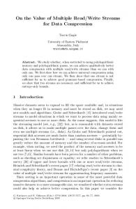
Performance The AC string matching algorithm has a deterministic worst-case lookup time. Once the state tables are generated and stored in the RAM, the packet is processed one byte at a time, and every byte requires one access to the RAM. The processing time mainly depends on the length of the packet and the RAM access time. The RAM access time depends on the RAM size which is proportional to the number of strings and the number of characters per string. As discussed in Section 3.2.3, using a simple classification technique to divide the rules into smaller rule sets generates separate FSMs that can run in parallel. This not only significantly reduces the size of the state tables but also increases the throughput by exploiting parallelism between the packets and different rule classes. Figure 9 shows the throughput of the accelerator where CACTI version 3.2 [15] was used to model the on-chip RAM. The figure plots the performance in terms of processing throughput (Gbps) for different FSM counts (1, 4, 8) and for rule sets with sizes up to 3,000 characters. We see that higher throughput is achieved by using more FSMs in parallel. By using 8 FSMs a throughput of around 14Gbps is achieved as opposed to 7 and 2Gbps for 4 and 1 FSM(s), respectively. We also notice that the throughput degrades as the number of characters grows. The throughput for 8 parallel FSMs decreases to about 5Gbps for 3000 characters. The performance degradation is due to the fact that as the number of characters increases, the number of states increases and the state table size increases as well.
Throughput (Gbps)
1 FSM
4 FSMs
8 FSMs
16 14 12 10 8 6 4 2 0 0
1000
2000 No. of Characters
3000
Figure 9: Throughput for Different Character Counts
11
4000
Comparison with Previous Work Table 4 compares the performance of our design with regular expressions/FAs, discrete comparators and CAMs based designs. The performance numbers for a Bloom filter implementation were not available. The data for the other designs was obtained from Sourdis et al. [9]. It is clear that our design out performed Sidhu’s NFAs, Cho’s discrete comparators, and Gokhale’s CAMs in terms of throughput. On the other hand, Sourdis’s pre-decoded CAMs used extensive fine grain pipelining to increase the throughput to 9.7 Gbps. By using 8 FSMs (i.e., 64 bit input) our accelerator achieves a throughput of about 10 Gbps and exceeds pre-decoded CAMs speed. Another advantage over Sourdis’s design is the low cost and power requirements of RAMs compared to CAMs. Table 4: Comparison of String Matching Implementations
Description Aldwairi et al. State tables/RAM Sourdis et al. [9] Pre-decoded CAMs Gokhale et al.[12] CAMs/Comparators Cho et al.[11] Discrete Comparators Sidhu et al.[6] NFAs/Regular Expression
3.2.7
Input Bits 64 32 32 32 32 8
Device Altera EP20k400E Altera EP20k400E Virtex2 6000 VirtexE-1000 Altera EP20K Virtex 100
Throughput(Gbps) 10.1 5.0 9.7 2.2 2.9 0.75
Logic Cells/Char 15 3.56 15.2 10.6 ~31
Conclusions: IDS Acceleration for EN-Morph
We have studied the Snort rules set and have shown that 87 percent of the rules have content. This further emphasizes the need for hardware acceleration for content matching. We have also presented a configurable string matching accelerator based on a memory implementation of the AC FSM where the state tables are directly stored in the RAM rather than the high level tree data structure. This results in a small memory requirement that is likely to fit in on-chip SRAM. We have shown that the accelerator can achieve up to 14 Gbps throughput with a simple classification algorithm which highlights the importance of classification algorithms. We also showed that our design outperformed the previous work published in this area.
3.3
Packet Classification Acceleration
The ever-increasing demand for feature and performance requirements in routers has resulted in an evolution of networking processors. The intelligence being built into the edge routers requires additional processing and deeper examination of packets. Sophisticated Network Processors utilize embedded processors for programmability and coprocessor units to accelerate critical tasks of forwarding, firewalling and differentiated services. We propose the design of a configurable co-processor unit that forms a part of the Polymorphous chip architecture for Network Processors. The architecture utilizes an embedded two-issue VLIW processor. Figure 10 below shows the overall architecture of the Network Processor Unit. The pipelined configurable co-processor is capable of performing firewall, differentiated services and forwarding for IPv4 and IPv6. The engine provides faster lookups, faster updates and memory compaction. The engine scales with the number of IP addresses, firewall rules and differentiated service rules.
12
Figure 10: Network Processor Unit
The basic goals of our design are 1) 2) 3) 4)
To perform fast next hop address lookup and packet classification based on an incoming packet, For the design to be morphable by software, To allow for faster updates, and To have memory optimizations with configurable boundaries.
We use an algorithmic approach to IP forwarding, originally developed by Mehrotra et al. [23] for trie construction and SRAM compaction. Their approach achieves a performance of 15 million look-ups per second and an update time of 300 ms. This algorithm however does not allow for faster updates, and is limited to the function of forwarding. We propose an architecture for a single classification engine using an array of tries for multi field classification. We also propose a solution for faster updates. Our design is configurable and morphable. We achieve a performance of over 28 million lookups per second for these tasks. We also address the critical table build up problem, outlining a solution that can sustain 125 updates per second, and takes less than 8 ms to complete updates. The solution described herein outperforms CAM based solutions in terms of power consumption, area, and cost while remaining competitive in terms of throughput and update times. Packet forwarding and classification are memory and computation intensive tasks. In our design we propose a strategy for optimizing IP address and rule storage by preprocessing the entries to reduce the best-case complexity for rule lookup. The design’s pipelining enables faster lookups and increased throughput and the memory and stage design allow for faster updating 3.3.1
Related Work
Various designs for fast classification engines exist today whose underlying architecture is based on CAM or trie data structures to partition the routing/rule tables. Girija et al [24] proposed a CAM based design. CAM engines, despite their increased power requirements, cost and board area are used in several coprocessor design. CAMs are inefficient in representing filters with port ranges. There are several other algorithmic alternatives that, either consume more memory, or have increased memory accesses or suffer from scalability issues. Existing trie-based schemes include direct and indirect lookups. These schemes require large amounts of memory to store the forwarding tables. The number of lookups is small (1–2) for these schemes however they do not scale well with number of entries. Binary tries store data fairly efficiently. However, they require a large number of memory accesses compared to the direct or indirect lookup schemes. Variations of the basic binary trie such as Patricia [17] and LC tries [18] improve performance to some extent, but the average number of memory accesses is still fairly large. Basu et al [19] use pipelined Forwarding engines with fast incremental updates that balance memory utilization across multiple pipeline stages and minimize disruption to the forwarding process caused by route updates. This system however suffers from scalability issues, as the memory requirements per stage make the implementation of an on-chip
13
memory difficult. For a million entries in the forwarding table their scheme has memory increased by a factor of 5 over our proposed design. Their design also supports only IPv4 and also lacks the configurability feature, which is key in configuring the memories and altering the boundaries for better trie distribution. Sawhney [28], in his thesis focuses on a forwarding engine for a million entries IPv6 routing tables. Memory requirements are analyzed for a trie-based scheme and a binary search scheme for IP address lookup. The hardware described, however, is not pipelined and does not support IPv6. 3.3.2
Algorithm
Mehrotra et al. [23] propose an algorithm that compacts the trie data structure to easily fit it on a on-chip SRAM. The row of the DRAM is calculated by the SRAM and the next hop address is read from the DRAM. This work is the basis for our design. We alter the memory to allow faster updates and pipeline the design to handle faster lookups as well as support for IPv6. The SRAM and DRAM databases are built from the conventional multiway trie structure. The SRAM database contains information that represents the topology of the trie, while the DRAM contains the next-hop addresses corresponding to the leaves of the trie. In addition to the SRAM and DRAM databases, an array (Level) is also maintained in the SRAM. The route lookup is done in two stages. In the first stage the SRAM is used to traverse to the longest matching leaf node in the trie, while in the second stage the DRAM is read to get the next-hop address. The data structure to be stored in the SRAM and DRAM are built from the corresponding multiway trie. Figure 11 above shows a 4-way trie. We describe the implementation using a 16-way trie, although any degree of trie can be built. The trie is built as follows:
Figure 11: Sample Four-Way Trie and its Bit Pattern
Step 1: Read each entry from the routing table and store it in a list. Sort the list in ascending order. For prefixes of differing lengths where one prefix forms the beginning of the other, the prefix with fewer prefix character is considered to be shorter For example, 10* is considered smaller than 100*. This ensures that while building the trie, parent nodes are processed before child nodes. Step 2: Create the root node of the trie and initialize the child node pointers to NULL. Step 3: Read each entry from the list and expand if necessary to complete the trie (to make sure that every internal node has X children, where X is the trie degree). Add appropriate nodes to the trie along with their next-hop addresses.
14
Step 4: Once the trie is built, construct the SRAM and DRAM data structures and the array Level via a breadth-first traversal of the trie. The SRAM is built by writing a 1 for every internal node and a 0 for leaf nodes, as shown in Figure 12. When constructing the SRAM data, we assume the existence of the first “1” which represents the root node and hence it does not need to be stored. The DRAM is built by writing an entry for every node in the trie in a breadth-first order. The Trie depth is given by the formula: Trie depth = No. of Address bits/log2X, where X is the degree of the trie. Trie depth is also the number of lookups required during insertion of an entry into the trie in the worst case. Since building the trie requires inserting N entries, where N is the total number of entries in the routing table, the total number of memory lookups while building the trie is: Memory Lookups = N * D, Where N is the total number of entries in the routing table, and D is the depth of the trie. 3.3.3
SRAM Compaction
Mehrotra’s [23] trie-based approach is a novel method to compress the forwarding table information by reducing the trie path-information. The required SRAM is small enough (about 35KB for a routing database 30,000 entries) to easily fit on a chip. This is significantly important especially when moving to IPv6 where larger routing tables or multiple tables for different hierarchies are used. The data for our case, using this scheme is compacted to approximately 2 bytes for every entry in the routing table (for a 16-way trie constructed with a million entries). Also, the overall memory consumption (SRAM and DRAM) using this scheme is almost half that required in conventional implementations. The amount of compaction achieved is much higher than other existing schemes, making a hardware implementation feasible. The compacted information can be stored in an on-chip SRAM and the final next-hop addresses are stored in an off-chip DRAM. To perform a route lookup, trie traversal is done in the SRAM and a final DRAM access is required to determine the next hop address. 3.3.4
The Array of Tries
The Diffserv and Firewall engines are built based on an array of tries. To start constructing this array the IP address field (source/destination) is utilized since it guarantees enough uniqueness. We show the construction of the array of tries in Figure 12.
15
Figure 12: Array of Tries
The first trie is built on the source IP address and the second corresponding trie is built for destination IP addresses that share this source IP address. Based on information from the current firewall and Diffserv rule sets we infer that there can be packets originating from a single source to multiple destinations. Thus the search for the destination address is narrowed down. The result of traversing the destination trie generates pointers to a memory populated with the remaining fields, where a direct comparison can be made to determine the action. 3.3.5
Range Lookups
Port number ranges and IP address ranges are a common occurrence in rule sets. Srinivasan et al [25] propose a simple mechanism of converting ranges to prefixes. The ranges are thus pre-processed to prefixes and are translated into part of the tries. Gupta et al [20] further define that a range of width W can be represented by at the most 2W- 2 prefixes.
3.3.6
Design and Implementation
IP address and rule information can be maintained as a trie for fast address lookup and search to determine membership of the incoming packet. We use the trie approach for IP forwarding and an Array of tries for Differentiated services and Firewall. Some of the important design decisions for a Trie are 1) The number of entries in the trie, 2) The IP version, and 3) The SRAM compaction. The design has four stages each of which is pipelined internally. The memory for each of these stages is partitioned based on the address spaces and each partition is further divided based on the levels of which they are comprised. 3.3.7
Block Diagram
We discuss the block architectures of the forwarding engine, firewall engine and differentiated services engine in this section.
16
3.3.8
Pipeline stage
The forwarding engine consists of four stages. The stages are split on the basis of levels of the Trie. For our implementation, we chose the order of the trie to be 16 since the IPv4 address is 32 bits long the depth of the trie is 8. Similarly the depth of 128 bit long IPv6 address is 32. In Figure 13 we show the different stages connected together.
Figure 13: Pipeline Stages
Figure 14 shows the internal blocks of a single pipeline. The Sum of 1’s function is implemented using a Brent Kung adder. The four basic building blocks of a single pipeline are: 1) 2) 3) 4)
SRAM Access, Mask Generation, Sum of 1’s, and Final state logic.
17
Figure 14: Logic Blocks
Memory for Stage 1 consists of the trie from level 0-7. Since IPv4 consists of only 8 levels, the lookup or classification for IPv4 ends in Stage 1 and does not traverse through the rest of the stages. Stage 2 consists of the trie from levels 8-15. Stage 3 consists of trie from level 16-23 and Stage 4 consists of trie from level 24-31. Typically IPv6 prefixes are 64 bits wide hence the output can be obtained by traversing through stages 1 and 2. We do not maintain a constant look up time hence the next address is obtained when the trie traversal ends. Each pipeline cycles through a stage 8 times to traverse the 8 levels of the trie. The pipelines have been designed to avoid memory contention. Figure 15 depicts the pipeline structure within each stage. Incoming packets are fed into a stage at the rate of one packet every 9 cycles to maintain a constant output rate. An FSM controls the entry of packet into the pipeline.
18
Figure 15: Forwarding Engine Stage Diagram
Figure 16 shows the components external to the lookup engine. Each stage has its dedicated memory that is populated with corresponding trie data.
Figure 16: Stage Pipeline with Memories
When a packet is received at stage 1 the trie from level 0-7 is traversed based on their source IP address. If the prefix to be matched is longer than 32 bytes then the packet is passed to the next stage. For an IPv4 packet, stage 1 points to the DRAM to look up the next hop address, but for a Firewall and Diffserv Engine, it forwards the packet to traverse the tries of the destination addresses, the result of which directs the packet to the corresponding fields in the memory that need to be compared. This is achieved by creating filters in software.
19
The filter could also be created based on the destination IP addresses, which in turn point to a subset of source IP addresses. The uniqueness of the IP addresses gives the advantage of smaller search space. There is no substantial degradation in performance seen in the event such uniqueness does not exist. 3.3.9
Memory Structure for Forwarding Engine
The memory structure as depicted in Figure 17 is one of the driving forces in the efficiency of the design. The address space of the IP addresses are split based on the first octet of the IP address; the different ranges are then created for the IP addresses. This feature in the design is configured by software. The memory is further partitioned into different levels. This enables different stages to access the memory without memory contention. In the event of an update a new trie is constructed in software and loaded onto a spare memory for swapping. Each address space occupies typically 288 KB. Software prescribes the number of address spaces and their boundaries. 3.3.10
Memory Structure for Firewalling and Diffserv Engine
The memory structure for the Firewalling and Diffserv is similar to the Forwarding engine but contains additional memories for secondary trie and multiple fields of the Differentiated services rules. The memories are separated based on the protocol field and then based on the source or the destination IP addresses. Hence the memories are indexed using the Protocol field and then use the source and destination addresses. Level 0 -7
Level 8-15
Level 16-23
Level 24-31
Address Space 1
Address Space 1
Address Space 1
Address Space 1
Address Space 2
Address Space 2
Address Space 2
Address Space 2
Address Space 3
Address Space 3
Address Space 3
Address Space 3
Address Space 4
Address Space 4
Address Space 4
Address Space 4
Address Space 5
Address Space 5
Address Space 5
Address Space 5
Address Space 6
Address Space 6
Address Space 6
Address Space 6
Address Space 7
Address Space 7
Address Space 7
Address Space 7
Address Space 8
Address Space 8
Address Space 8
Address Space 8
Figure 17: Memory Structure for the Different Stages
We assume the Differentiated Services to be provided by the Internet Service Providers on the basis of rules, which would classify packets based on the following fields: 1) 2) 3) 4) 5) 6) 7)
Protocols, Ports (including ranges), Source IP address (including ranges), Destination IP addresses (including ranges), Type of Service field, Differentiated Services Code Point (DSCP) value, and Transmission Control Protocol flags.
20
3.3.11
Performance
We present our performance results for an ASIC based implementation. For the ASIC implementation the design was synthesized using the Virginia Tech 0.25um library. The timing analyses were done with a clock skew of 300ps. The synthesis provides a cycle time of 2 ns for the design with a total cell area of 4.8 sq. mm. It takes typically 32 cycles to process IPv4 packets and 64 cycles to process IPv6 packet (with typical prefix length of 64 bits). We achieve a throughput of 28 million lookups per second. 3.3.12
Memory Requirements
The required SRAM is small enough to easily fit on a chip. The data in our case is compacted to approximately 2 bytes per entry as per the formula in [26] for a million entry routing table. We calculated the maximum SRAM requirement and the expected SRAM requirement for the forwarding engine. The maximum SRAM requirement arises from extreme cases that are not observed in present day routing tables. It is further observed that the expected SRAM requirement is less than that required for the actual routing tables. Therefore we use a scaling factor to allocate sufficient SRAM for the desired routing table size. The theorem explained in [26] shows that the expected SRAM memory (bits/entry) for n random uniformly distributed routing table entries is given by: E(Mem(bits/entry)) = M/ln(M), where M is the degree of the trie. In our case for a 16 degree trie the memory requirements (using a scaling factor of 3) are as follows: SRAM = 6Mbit * 3 = 18Mbits. Assuming a byte to store the port numbers, the memory requirement for the DRAM would be: DRAM = 18Mbit *8 = 144Mbits. The four memories (M0-M3), as shown in Figure 16 above, are split across the 4 stages and serve separate levels. From the prefix distribution of IP addresses described in [27], it is observed that the 24-bit prefixes (Level 6) are most dominant. For IPv6 packets the 64-bit prefixes are found to be the most dominant. Based on this information the memories M0-M3 have been partitioned. For a DiffServ and Firewall engine the typical memory requirements are likely to be less than the above since the number of entries (rules) are less. The number of rules for a DiffServ and Firewall are typically 20,000 and 10,000 respectively hence the trie memories for Diffserv is approximately 90 KB and for Firewall it is 45 KB.
3.3.13
Conclusion for DiffServ and Firewall Engine
Our design achieves a throughput of 28 Million lookups per second. We parallelized the design by creating deep pipelines. SRAM compaction results in reduced memory requirements as compared to other designs. The area for our design is 4.8 sq mm. in a 0.25um technology. The functionality of forwarding engines has now grown to encompass multi-field classifications. There is a need for a system that can efficiently perform the functions of Firewall Differentiated Services and Forwarding. These engines should also not suffer from constraints such as excessive memory requirements and slow updates. The design we propose uses SRAM compaction with a memory of 2.25 MB for typical cases and performs updates in 8 ms. The pipeline makes the design faster and increases the throughput. We show that with our algorithmic approach we can achieve a
21
performance of over 28 million lookups per second for these tasks. We also address the critical table build up problem, outlining a solution that can sustain 125 updates per second, where each update takes less than 8 ms to complete.
22
4
Technology Transfer
We are investigating a number of avenues for technology transfer through commercial vendors. This is an ongoing process and will continue beyond the end of the program. Activities towards this end include the following: • Conference presentations at a number of venues, including the Workshop on Building Block Engine Architectures for Computers and Networks (Park Plaza, Boston, Massachusetts, October 10, 2004) • Journal publications in preparation • Visits, including detailed discussions with the following networking companies: Foundry Networks, CISCO Systems, and Juniper Networks.
23
5
Recommendations
The EN-Morph Mode project has made tremendous strides in a short amount of time with modest funds. We have developed an embedded version of TRIPS, called CLAW, and two accelerators, one for intrusion detection and one for routing packet classification (DiffServ and Firewall), to enable EN-Morph to operate at competitive throughput levels as compared to industrial designs. In addition, EN benchmarks were provided to the PCA community. The future directions of this research are to seek technology transfer, as outlined above.
24
6
References
[1] K. Sankaralingam, et al., “TRIPS: A polymorphous architecture for exploiting ILP, TLP, and DLP,” ACM Transactions on Architecture and Code Optimization, Vol. 1 , No. 1, March 2004. [2] M. Roesch, “Snort - lightweight intrusion detection for networks,” in Proceedings of LISA99, the 13th Systems Administration Conference, 1999. [3] A. Aho and M. Corasick, “Efficient string matching: An aid to bibliographic search,” in Communications of the ACM, Vol. 18, No. 6, pp. 333-343, June 1975. [4] R. Boyer and J. Moore, “A fast string searching algorithm,” in Communications of the ACM, Vol. 20, No 10, pp. 762–772, October 1977. [5] S. Antonatos, K. Anagnostakis, and E. Markatos, “Generating realistic workloads for network intrusion detection systems,” in ACM Workshop on Software and Performance, April 2004. [6] R. Sidhu and V. Prasanna, “Fast regular expression matching using FPGAs,” in Proceedings of the 11th Annual IEEE Symposium on Field Programmable Custom Computing Machines (FCCM01), April 2001. [7] D. Carver, R. Franklin, and B. Hutchings, “Assisting network intrusion detection with reconfigurable hardware,” in Proceedings of the 12th Annual IEEE Symposium on Field-Programmable Custom Computing Machines (FCCM02), April 2002. [8] I. Sourdis and D. Pnevmatikatos, “Fast, large-scale string match for a network intrusion detection system,” in the Proceedings of 13th Annual IEEE International Conference on Field Programmable Logic and Applications, April 2003. [9] I. Sourdis and D. Pnevmatikatos, “Pre-decoded CAMs for efficient and high-speed NIDS pattern matching,” in Proceedings of 14th Annual IEEE Symposium on Field Programmable Custom Computing Machines (FCCM04), April 2004. [10] S. Dharmapurikar, M. Attig and J. Lockwood, “Design and implementation of a string matching system for network intrusion detection using FPGA-based bloom filters,” in Proceedings of the 14th Annual IEEE Symposium on FieldProgrammable Custom Computing Machines (FCCM '04), April 2004. [11] Y. Cho, S. Navab and W. Mangione-Smith, “Specialized hardware for deep network packet filtering,” in Proceedings of the 12th Annual IEEE International Conference on Field-Programmable Logic and Applications, September 2002. [12] M. Gokhale, D. Dubois, A. Dubois, M. Boorman, S. Poole, and V. Hogsett, “Granidt: Towards gigabit rate network intrusion detection technology,” in Proceedings of the 12th Annual IEEE International Conference on FieldProgrammable Logic and Applications, September 2002. [13] M. Fisk and G. Varghese, “Applying fast string matching to intrusion detection,” September 2002. [14] N. Tuck, T. Sherwood, B. Calder and G. Varghese, “Deterministic memory-efficient string matching algorithms for intrusion detection, in Proceedings of the IEEE INFOCOM Conference, March 2004. [15] http://research.compaq.com/wrl/people/jouppi/CACTI.html. [16] P. Gupta, S. Lin, and N. McKeown, “Routing Lookups in Hardware at Memory Access Speeds,” in Proceedings of the IEEE INFOCOM Conference, San Francisco, CA, 1998, pp. 1382–91. [17] K. Sklower, “A Tree-Based Routing Table for Berkeley Unix,” Tech. Rep., UC Berkeley. [18] S. Nilsson and G. Karlsson, “IP-Address Lookup Using LC-Tries,” IEEE JSAC, Vol. 17, June 1999, pp. 1083–92. [19] Anindya Basu and Girija Narlikar, “Fast Incremental Updates for Pipelined Forwarding Engines,” Proceedings of the IEEE INFOCOM Conference, 2003. [20] Gupta, McKeown. “Alogrithms for packet classification,” Computer Systems Laboratory, Stanford University. [21] J. Xu and al., “A novel cache architecture to support layer-four packet classification at memory access speeds,” in Proceedings of the IEEE INFOCOM Conference, March 1999. [22] F. Baboescu, S. Singh, G. Varghese, “Packet classification for core routers: Is there an alternative to CAMs?,” Proceedings of the IEEE INFOCOM Conference, 2003. [23] P. Mehortra, P. Franzon, “Novel Hardware Implementation for Fast Address Lookups,” 2002 Workshop on High Performance Switching and Routing. [24] G. Narlikar, A. Basu, and F. Zane, “CoolCAMs: Power-efficient TCAMs for forwarding engines,” in Proceedings of the IEEE INFOCOM Conference 2003. [25] V. Srinivasan, G.Varghese, S.Suri, M.Waldvogel. “Fast and Scalable Layer four Switching”, in Proceedings of the SIGCOMM Conference, 1998.
25
[26] P. Mehrotra, “Memory Intensive Architectures for DSP and Data Communication”, Ph.D. Dissertation, Department of Electrical and Computer Engineering, North Carolina State University, 2002. [27] M.A Ruiz-Sanchez, E.W Biersack, and W. Dabbous, “Survey and taxonomy of IP address lookup algorithms,” IEEE Network, April 2001. [28] I. S. Sawhney, “Forwarding Engine for IPv6,” M.S. Thesis, Department of Electrical and Computer Engineering, North Carolina State University, 2004.
26