access times on data) â cache storage buffers the data of level x + 1 .... 1 TB huge (external) hard-disk ... RAID levels 2 until 6 restore defective data using parity.
Lecture
Database Implementation Techniques / Databases II OvGU Magdeburg, WinSem 2009/2010 Sandro Schulze, Gunter Saake
{sanschul,saake}@iti.cs.uni-magdeburg.de.
VL Databases II – 0–1
3. Storage Management � Storage media � Storage arrays: RAID � Backup media: Tertiary storage � Structure of (physical) storage � Pages, records and adressing � Buffer management in detail � Cryptographic methods
VL Databases II – 3–1
Storage Media � Several purposes: � Provide data for processing � Long-term data storage (and at the same time
having them available anyway) � Archiving data in the long term and cheap by accepting longer acces time � In this section: � Storage hierarchy � Hard-disk/magnetic disk � Capacity, costs, speed
VL Databases II – 3–2
Storage Hierarchy 1. Extreme fast processor with register 2. Very fast cache memory 3. Fast main memory 4. Slow secondary storage with randomized access 5. Very slow nearline tertiary storage with automatically provided storage media 6. Extreme slow offline tertiary storage with manually provided storage media Tertiary storage: CD-R (Compact Disk Recordable), CD-RW (Compact Disk ReWritable), DVD (Digital Versatile Disks), magnetic tapes, e.g., DLT (Digital Linear Tape) VL Databases II – 3–3
Cache Hierarchy (I) � Characteristics of storage hierarchy � Level x (e.g., level 3, main memory) has a
considerably faster access time than level x + 1 (e.g., level 4, secondary storage) � At the same time, much higher costs per memory/storage space � Thus, much lower capacity � Durability of data increase corresponding to the levels
VL Databases II – 3–4
Cache Hierarchy (II) � Reducing access vacancy (differences between
access times on data) ⇒ cache storage buffers the data of level x + 1 on level x: � Cache (equivalent to main memory cache) ⇒ faster semiconductor technology for the supply of data to the processor (level 2 in storage hierarchy) � Disk storage cache in main memory: Buffer � Cache in the context of WWW (accessing data over HTTP): Part of disk storage, which buffers parts of data, provided by the internet
VL Databases II – 3–5
Access Vacancy � Magnetic disk 70% more storage density per year � Magnetic disk only 7% faster per year � CPU power increased by 70% per year � Access vacancy between main memory and magnetic
disk is 105 � Measurements: � ns for nanoseconds (i.e., 10−9 seconds) , ms for
milliseconds (i.e., 10−3 seconds) � KB (KiloByte = 103 bytes), MB (MegaByte = 106 bytes), GB (GigaByte = 109 bytes) und TB (TeraByte = 1012 bytes)
VL Databases II – 3–6
Numerical Access Vacancy (2005) Type of storage
typical access time
Cache
6 ns
typical capacity
512 KB up to 32 MB Main memory 60 ns 32 MB up to 1 GB — Access Vacancy 105 — Magnetic disk 12 ms 1 GB up to 10 GB Disk farm or array 12 ms in the range of TB
VL Databases II – 3–7
Access Locality � Caching principle does not work, if always new data
(from higher levels) is needed � In most use cases: Locality of (data) access � This means, mostly the access takes place on data
provided by the cache of the respective level (usually more than 90%) � Hence: Buffer management of database system is an
important concept
VL Databases II – 3–8
Hard-Disk/Magnetic Disk
VL Databases II – 3–9
Recording Component � Disk pack with 5 to 10 disks � Up to 10.000 revolutions per minute (rpm) � For every disk surface a read/write head (i.e. between
10 and 20) � Disk surface: concentrical circles (Tracks) � Stacked tracks of all disk surfaces: Cylinder � Tracks consist of Sectors (512 bytes, 1 KB) � Sector contains data for autocorrection of errors —
parity bits or Error Correcting Codes (ECC) � Smallest access unit on disk: Block (multiple of sector
size)
VL Databases II – 3–10
Positioning Component � Addressing of blocks realized by cylinder/track/sector
number � Access time (from request to the transfer of block
content): � Seek time (time for moving access arm) � Latency time (time for rotating to the respective sector ) � Data-transfer time (time for data transfer)
VL Databases II – 3–11
Typical Characteristics of Hard-Disks Characteristic Average seek time Revolution time Track capacity Disk surface(s) Cylinder Capacity
1998 8 ms 6 ms 100 KB 20 5000 10 GB
1985
1970
16 ms 30 ms 16.7 ms 16.7 ms 47 KB 13 KB 15 19 2655 411 1.89 GB 93.7 MB
VL Databases II – 3–12
Controller and further Developments (Disk) Controller � Transfer rate: 40 MB per second � IDE- or SCSI-Controller
Further developments � Disk farms ⇒ loose coupling of few but big disks;
distribution of data on disk realized by operating system or database system
� Disk arrays, esp. RAID systems (Redundant Array of
Inexpensive Disks): High amount of cheap standard disks (8 bis 128) organized by an intelligent controller ⇒ Increase of fault tolerance (reliability) or increase of parallelism of access (increase in efficiency) VL Databases II – 3–13
Storage Capacity and Costs I Size 1 KB 0.5 KB 30 KB 1 MB 5 MB 20 MB 500 MB 1 GB 4.7 GB 10 GB 100 GB 200 GB
Information or Medium = 1.000 (precise: 1024 Byte) Book page as text scanned, packed book page = 1.000.000 (...) The bible as text scanned book CD-ROM; Oxford English Dictionary = 1.000.000.000 (...) Digital Versatile Disk (DVD) packed movie one floor of a library Capacity of a video tape
VL Databases II – 3–14
Storage Capacity and Costs II Size 1 TB 1 TB 1 TB 11 TB 20 TB 20 TB 1 PB 1 PB 15 PB 200 PB
Information or Medium = 1.000.000.000.000 (...) Library with 1M books huge (external) hard-disk big(gest) Data Warehouse (Wal-Mart) huge storage/disk array Library of Congress books stored as text = 1.000.000.000.000.000 (...) scanned books of a national library worldwide hard-disk production in 1996 worldwide magnetic tape production in 1996
VL Databases II – 3–15
Storage Medium and Costs (ca. 1999) Storage Type
Storage Medium Preis (Euro/MB)
Main Memory 64-MB-SDRAMs Secondary Storage 10-GB-IDE-HD Tertiary Storage opt. disk 5 GB 650-MB-CD-RW 650-MB-CD-R 70-GB-DLT-Band
0.5000 Euro 0.0275 Euro 0.0160 Euro 0.0150 Euro 0.0015 Euro 0.0010 Euro
VL Databases II – 3–16
Current Developments � Classical storage hierarchy in change � Flash storage � Well-known from digi cams, MP3 player, PDA, etc. � Block by block deletion before every writing • Sequential reading identical with disk • Random reading considerably faster • Writing is more slowly • Durability is limited to 100.000 until 1.000.000
writing processes � 256 GB Chips for 40 Dollar predicted for 2012 • Even the still more expensive than disk (approx. by factor 10) � RAM storage ⇒ Even faster, random access � Main memory databases
VL Databases II – 3–17
Storage Arrays: RAID � Connection of cheap standard magentic tapes to one
logical device supervised by a certain controller � Distribution of data over the several physical disks is
realized by the controller � Two opposed objectives: � Increasing the fault tolerance (system stability,
reliability) by redundancy � Increase in efficiency through parallelism of access
VL Databases II – 3–18
Increasing of Fault Tolerance � Usage of additional disks for storage of duplicates
(mirrors) of the original data ⇒ Failures: switch over to mirror disk � Particular RAID-Levels (1, 0+1) permit such a mirroring � Alternative: Control information, e.g., parity bits, are
stored on a separate disk instead of the same sector as the original data � RAID levels 2 until 6 restore defective data using parity
bits or Error Correcting Codes (ECC) � Parity bit can detect and correct a media error (if the
defective disk is known)
VL Databases II – 3–19
Increase of Efficiency (I) � Database distributed over several disks, that can be
accessed parallel ⇒ Access time decreases nearly linear to the number of disks available � Distribution � Bit by bit (i.e., in the case of 8 available disks, one
byte can be distributed) � Byte by byte (bytewise) � Block by block (blockwise)
VL Databases II – 3–20
Increase of Efficiency (II) � Higher RAID levels (from level 3) combine error
correction and bit- or blockwise distribution of data � Differences (to lower levels): � faster access on certain data � increased throughput for many transactions
(queued for parallel processing) by load balancing the overall system
VL Databases II – 3–21
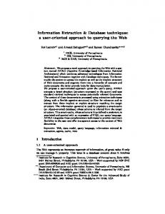
RAID Levels 0, 1 und 0+1 Blocks
A
B
C
D
A
C
B
D
A
B
A
B
C
D
C
D
A
C
A
C
RAID 0
RAID 1
B
D
B
D
RAID 0 + 1
VL Databases II – 3–22
RAID Level 0 � Data blocks are distributed on physical disks (available
for the RAID system) by rotation principle (Striping) � Here: blockwise Striping � Advantages: � Parallel reading of data of sequenced blocks � Load balancing if many parallel read TAs are
queued (needed blocks exist probably on different disks) � Disadvantages: � No speedup for random access on one specific
block � No redundancy or control information VL Databases II – 3–23
RAID Level 1 � Blocks (to be stored) are mirrored/duplicated on
several disks � Disadvantages: � Solely increase of efficiency: load balancing for
reading of parallel transactions � Advantages � In case of errors simply switch to one of the mirror
disks � Subsequently, the defective disk can be replaced and filled with correct data
VL Databases II – 3–24
RAID Level 0+1 � Combination of level 0 and 1 to obtain the advantages
of both � Foundation for higher RAID-Levels: Combination of
Striping for increase of efficiency and actions for error correction are retained � However, doubling the memory space requirements is
avoided � Instead of mirror disks, control information, e.g., parity
bits or Error Correcting Codes (ECC) are used
VL Databases II – 3–25
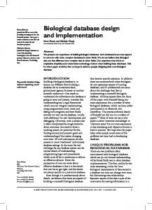
RAID Levels 2 und 3
RAID 2
RAID 3
A[1]
A[2]
B[1]
B[2]
C[1] D[1]
A ECC[1]
A ECC[2]
B ECC[1]
B ECC[2]
C[2]
C ECC[1]
C ECC[2]
D[2]
D ECC[1]
D ECC[2]
A[1]
A[2]
A ECC
B[1]
B[2]
C[1]
C[2]
C ECC
D[1]
D[2]
D ECC
...
...
B ECC
VL Databases II – 3–26
RAID Level 2 � Bitwise Striping � Parity bits or extended ECC on additional disks � Reading in one data requires 8 parallel read operations � Access not more efficient, but the overall throughput is
octuplicated (i.e., eight times higher)
VL Databases II – 3–27
RAID Level 3 � Principle: Disk detects error ⇒byte can be
reconstructed with the help of the 7 remaining bits and one parity bit
� Parity bits use only one single, dedicated disk � Control information are reduced to the basics, and
thus, memory space is reduced further
VL Databases II – 3–28
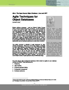
RAID Levels 4 to 6 A
C
B
A ECC
D
B ECC
RAID 4
C ECC D ECC
A
D
RAID 5 E ECC F ECC
A
RAID 6
D
B
E
C
C ECC
A ECC
D ECC
B ECC
B
E
C
F
...
F
...
A ECC 1
A ECC 2
B ECC 1
B ECC 2
...
VL Databases II – 3–29
RAID Level 4 � Blockwise Striping � One dedicated disks for parity bits � Small data sets are readable more efficient, since only
one physical disk is affected
VL Databases II – 3–30
RAID Level 5 � No additional, dedicated disk for storage of parity bits � Instead, parity bits are distributed over existing disks � Hence, bottleneck of level 3 and 4 is removed: So far,
every write operation on parity disk as well ⇒ every write operation waits for dedicated disk � Improved load balancing by usage of different disks
VL Databases II – 3–31
RAID Level 6 � Based on RAID level 5 � More control information on data disk � More than one media error can be corrected � Only barely implemented
VL Databases II – 3–32
Overview RAID Levels Striping blockwise Striping bitwise Copy Parity Parity dedicated disk Parity distributed Detecting several errors
0 √
1 √
0+1 √ √
2
3
√
√
√
√ √
4 √
5 √
6 √
√ √
√
√
√
√
VL Databases II – 3–33
Comparison of particular RAID Level (I) Application profile � Number of read operations � Number or write operations � Requirements regarding system stability
VL Databases II – 3–34
Comparison of particular RAID Level (II) Characteristics � Fastest error correction: Level 1 (well-suited for log
files) � Solely increase of efficiency: Level 0 (well-suited for
video server) � Level 3 and 5 improvements of level 2 and 4 � Level 3 and 5 for working with huge amounts of data � Level 3 increases overall throughput � Level 5 improves random access � Lvel 6 would be improvement of level 5, but rarely
realized � Archive media are not (!) replaced by RAID systems VL Databases II – 3–35
Backup Media: Tertiary Storage Requirements � Less used parts of database, with probably huge size
(Text, Multimedia) should be stored „cheaper“ than with standard mag tapes � Currently used databases have to be back upped
additionally (archiving) Tertiary storage: Medium replaceable � offline: Media have to be changed manually � nearline: Media are changed automatically (jukeboxes,
mag tape robots)
VL Databases II – 3–36
Optical Disks � CD-ROM, CD-R, CD-RW; DVD, DVD-R, DVD-RW,
DVD+RW, . . . � Differences: executable operations, storage capacity � Storage capacity CD: approx. 700 MB � Storage capacity DVD: 4.7 GB to 17 GB data � Optical disks and devices quite cheap � Although random access is possible, the access is
very slow (about 250 ms) � Durability is comparatively high (approx. 30 years) � Popular as storage for data required rarely but
continuous
VL Databases II – 3–37
Tapes � Very cheap medium with low cost devices � Access yet more slowly than optical disks � Sequential access: Transfer rate between 1 and 10 MB
per second (acceptable) � Random access: in the range of some minutes (on
average) � Very high capacity in the range of GBs (DLT (Digital
Linear Tape) contains up to 70 GB packed data) � Popular as archive storage
VL Databases II – 3–38
Jukeboxes and Robots � Shut down / Rewind, � Remove media from device, � Mounting the medium, � Grab new medium, � Loading of media and boot up
cost over 20 seconds with optical disks and more than 2 minutes with tapes � Typical capacities: Tape robots with more than 10.000
cartridges (range of petabytes possible)
VL Databases II – 3–39
Long-term Backup/Archival Aspects of durability: � Physical stability of the medium ensures the integrity of
data � Availability of devices and drivers ensure the
readability of data � Available meta data ensure the interpretability of data � Availability of programs, processing or working on the
data ensure the reusability of data
VL Databases II – 3–40
Physical Stability: Integrity � 10 years for magnetic tapes, 30 years for optical disks � In comparison to classical archival media, e.g., paper,
very low � However, integrity of data is even longer guaranteed
than other aspects
VL Databases II – 3–41
Readability � Problem: Which systems, used today, can read tapes,
floppy disks and punchcards mostly used in the 60s and 70s ? � new devices/systems would have to maintain
numerous parameters like recording formats, type of parity information etc. for several decades � Furthermore, procedure (of recording) not
standardized or standardization is enhanced continuously
VL Databases II – 3–42
Interpretability � Different codes for representation of characters
(EBCDIC, ASCII, 16-Bit-Unicode) � Document formats: Which (current) SW can read
formatted text documents, created by word processing SW in the 70s or 80s ? � Solution: Storage in open standards like page
description languages (Postscript) or markup languages (HTML, XML)
VL Databases II – 3–43
Management of Physical Storage Abstraction of specific storage and backup media Model: Sequence of Blocks SOI
Set−Oriented Interface
Data System ROI
Record−Oriented Interface
Access System IRI
Internal Record Interface
Storage System SBI
System Buffer Interface
Buffer Management FI
File Interface
Operating System DI
Device Interface VL Databases II – 3–44
Operating System Files (I) � Every relation or access path in one OS file
respectively � One or more OS files, relations and access paths are
managed by the DBS itself within these files � DBS itself manages the hard-disk and uses blocks in
their original form (raw device)
VL Databases II – 3–45
Operating System Files (II) Why not always using OS file management? � Platform (OS) independence � In 32-Bit operating systems: file size at most 4 GB � OS files only on one medium (storable) � OS-specific buffer management (i.e., blocks of
secondary storage are used in main memory) does not meet the requirements of DBS
VL Databases II – 3–46
Blocks and Pages � Assignment of physical blocks to pages � Usually with constant multiplier: 1, 2, 4 or 8 blocks (of
one track) on one page � here (for simplicity): „one block — one page“ � Adressing of higher levels of DBS via page numbers
VL Databases II – 3–47
Services � Allocation or deallocation of memory space � Fetch or write of page content � Allocation in a way, that logical consecutive data areas
(e.g., a relation) are preferably stored in consecutive blocks on disk � After numerous update operations: Reorganisation
methods � (Free) storage management: Doubly-linked list of
pages
VL Databases II – 3–48
Mapping of Data Structures � Mapping of conceptual level to internal data structures � Supported by meta data (in the Data Dictionary, e.g.,
the internal schema) Conc. level Internal level Relations → Log. files → Tuple → Records → Attribute values → Fields →
File system/Disk Phys. files Pages/Blocks Bytes
VL Databases II – 3–49
Alternatives of Mapping � Example 1: Every relation in one logical file, these files
alltogether in a single physical file � Example 2: Cluster storage – several relations in one
logical file
VL Databases II – 3–50
5588
Saake
6834
Korn
Korn
DBR MD MD
Main File 4711 Heuer 5588 Saake 6834 Korn
... ... ...
DBR MD MD
. ..
Index File DBR
...
Heuer
Place
...
4711
... ... ... ...
MD
...
Heuer
Surname
...
files
Index File
...
several logical
PANr
...
Relation
...
Common Form of Storage (I)
Saake
VL Databases II – 3–51
Common Form of storage(II)
files
5588 Saake
...
Korn
6834 Korn
... ... ...
. ..
DBR MD MD
DBR
...
4711 Heuer
MD
...
Heuer
...
several logical
Saake Main File
Index File
Index File
one physical file
...
4711 Heuer
...
5588 Saake
...
Heuer
.
Saake
DBR
...
Korn
.
6834 Korn
...
MD
...
MD
.
.
DBR
..
... MD
VL Databases II – 3–52
Adaptation of Records to Blocks � Records (maybe of variable length) have to be adapted
to blocks, consisting of a constant number of bytes: Blocking � Blocking depends on length of data fields/records
(variable or fix) � Records with variable length: Higher effort for read/write operations, record length has to be redetermined � Records with fixed length: Higher storage effort (overhead)
VL Databases II – 3–53
Blocking Techniques
Page p
Page p+1
Spanned Record
Page p
Page p+1
Unspanned Record
� Unspanned Records: every record in at most one block � Spanned Records: record probably in several blocks � Standard: Unspanned records (only in the case of
BLOBs or CLOBs spanned records are used)
VL Databases II – 3–54
Pages, Records and Adressing � Structure of pages (in storage management):
Double-linked list (Free-List) � Free pages in (free) storage management Before After 115
81
further header information
136
Offset 142
136
115
175
Tuple
...
VL Databases II – 3–55
Page � Header � Information about predecessor and successor page � Probably page number itself � Information about typ of record � Free space (available) � Records � Unassigned bytes
VL Databases II – 3–56
Page: Adressing of Records � Adressable units � Cylinder � Tracks � Sectors � Blocks or pages � Records in blocks or pages � Data fields/areas in records (e.g., a certain attribute) � Example: Address of record realized by page number
and offset (relative address from top of the page in bytes) (115, 142)
VL Databases II – 3–57
Page Access as Bottleneck � Measurement for the speed of DB operations: Number
of page accesses on secondary storage (caused by access vacancy) � Rule of thumb: Time of access ⇐ Quality of access
path ⇐ Number of required pages accesses
� Main memory operations not arbitrarily negligible
next slides: Types of Records
VL Databases II – 3–58
Pinned records � Pinned records are bounded to their position � Example: References (directly on record) by pointer
from other, hardly detectable page(s); e.g., moving of record (115, 142) to page 136 � Risk: Pointer referencing to nothing (dangling pointers)
VL Databases II – 3–59
Unpinned records � Unpinned records: References by „logical pointer“ � E.g.: Matriculaion number for referencing to a student
record � This logical pointer can be mapped to current address
at a central place (e.g., index file for student relation) � Disadvantage: Moving of record requires loading both
directly affected pages (source and target page of moving operation) as well as loading the index page � This is resolved by TID concept
VL Databases II – 3–60
Records with fixed length SQL: Data types with fixed and variable length � char(n) string with fixed length n � varchar(n) string with variable length with maximum
length n Structure of records, if all data fields with fixed length: 1. Administration block with � Type of record (if different types on one page allowed) � Deletion bit 2. Free space for adjusting the offset 3. User data of record
VL Databases II – 3–61
Records with variable length � Required in administration block: Record length l, so
that the length of the user data area d is known
l Length (or administration block)
d (useful) data
VL Databases II – 3–62
Records with variable length (II) a)
l
n
al1 A1
...
number attributes
aln An attribute values
attribute lengths
number attributes b)
l
n
attribute pointer
ap1
...
apn A1
atribute values ...
An
VL Databases II – 3–63
Storage of Records with variable Length � Strategy a): Every data field with variable length Ai
starts with a length pointer ali , specifying the length of the following data field � Strategy b): After length pointer l and number of
attributes at the beginning of the record, a pointer field ap1 , . . . , apn for all data fileds with variable length is established � Advantage of strategy b): easier navigation within one
record (even for records in pages ⇒ TID)
VL Databases II – 3–64
Application of variable Records „Repetition Groups“: List of values with same data type � Strings of variable length, e.g., varchar(n) are
repetition groups with char as basis data type ⇒ mathematical, this is the Kleene closure (char )∗ � Attribute values with a set or list nature, which should
be stored denormalized within the record (e.g., storage as nested relation or cluster storage); for a list of integer values this would be (integer )∗ � Address field for index file, which points to several
records for one attribute value (secondary index), i.e., (pointer )∗
VL Databases II – 3–65
Huge, unstructured Records � RDBS data types for very large, unstructured
Information: � Binary Large Objects (BLOBs): Byte sequences like images, audio or video sequences � Character Large Objects (CLOBs): Sequences of ASCII characters (unstructured ASCII text) � long fields generally exceed the limit of one page,
hence only non-BLOB fields are stored on original page
VL Databases II – 3–66
BLOB Storage: Solution 1 � Pointer as attribute value: Pointer points to the
beginning of page or block list, which contains the BLOB Block BLOB
� Advantage for insert, delete or modify operation � Disadvantage for random access within the BLOB
VL Databases II – 3–67
BLOB Storage: Solution 2 � BLOB directory as attribute value: � Size of BLOB � Further administration information � Several pointers, referencing to single pages � Advantage: fast access on partitions of the BLOB � Disadvantage: Fixed, limited (maximum) size of the
BLOB (e.g., Gigabyte BLOB; 8-byte addressing, page size 1 KB ⇒ 8 MB for one BLOB directory)
� More efficient: B-Tree for storage of BLOBs (v.i.)
VL Databases II – 3–68
BLOB Storage: Solution 2 (II) BLOB Directory BLOB size Administration info. Pointer to block 1 Pointer to block 2 Pointer to block 3 ... Pointer to Block k
VL Databases II – 3–69
Addressing: TID Concept � Tupel-Identifier (TID) record address consisting of
page number and offset � Offset is used to reference within a single page ⇒ an
offset value of i points to the i-th entry in a list of tuple pointer at the beginning of the page
� Each tuple pointer contains offset value � Movements within a page: All references from „outside“
remain unchanged � Movements to another page: Old record is replaced by
new TID pointer � This two-staged reference not desireable for efficiency
reasons: Reorganisation in periodical intervals VL Databases II – 3–70
TID Concept: One-Staged Reference TID p
Page p i i
tuple pointer
i−th tuple
VL Databases II – 3–71
TID Concept: Two-Staged Reference TID p
Page p i i TID
Page q j
j−th tuple VL Databases II – 3–72
Buffer Management in Detail SOI
Set−Oriented Interface
Data System ROI
Record−Oriented Interface
Access System IRI
Internal Record Interface
Storage System SBI
System Buffer Interface
Buffer Management FI
File Interface
Operating System DI
Device Interface VL Databases II – 3–73
Functions of Buffer Management � Buffer : Designated part of the main memory � Divided into buffer frames, each frame can contain one
page from the hard-disk � Functions: � Buffer management has to search required page in � � � �
the buffer ⇒ efficient search techniques Parallel DB transactions: clever storage allocation within the buffer Buffer full: adequate page replace strategies Differences between OS buffer and DB buffer Specific application of buffer management: shadow storage concept VL Databases II – 3–74
Searching a Page � Direct Search: Linear search without additional means � Indirect Search: � Ordered or unordered table: all pages of buffer are
observed � Linked list: enables a faster, ordered insertion � Hash table: with adequate hash function an advantageous effort for searching and modifying is possible
VL Databases II – 3–75
Storage Allocation in the Buffer for several transactions to be executed in parallel � Local strategies: Disjunctive parts of the buffer are
made available for every transaction (size can be determined statically before execution of TA or dynamically at program runtime) � Global strategies: Access behaviour of all TAs
determines storage allocation (pages, jointly referenced by several TAs can be regarded better this way) � Strategies related to page type: Partition of the buffer:
Buffer frames for data pages, access path pages, data dictionary pages, . . .
VL Databases II – 3–76
Page Replace Strategies � Storage system requests page E2 , which is not in the
buffer � All buffer frames are reserved � Before loading E2 , a buffer frame has to be cleared � The page has to be selected by the strategies
described below � If page has been modified within the buffer, rewrite the
page to the hard-disk � If page has only be read within the buffer, it can be
overwritten(replaced)
VL Databases II – 3–77
Page Replace schematic
A1
E2
...
C1
E1
Secondary Storage
rewrite / replace
A1
A2
B1
B2
C1
C2
D1
D2
Buffer
load
... ... ... ...
An−1
An
Bn−1
Bn
Cn−1
Cn
Dn−1
Dn
E1
E2
...
...
...
Main Memory
Storage System
VL Databases II – 3–78
Page Replace: Techniques (I) � Demand-paging technique: Exactly one page in the
buffer is replaced by requested page � Prepaging technique: Besides the requested page
further pages, potentially required in future, are loaded into the buffer (e.g., reasonable for BLOBs) � Optimal strategy : Which page has the maximum
distance to the next usage? (not feasible, future reference behaviour not predictable) ; Feasible techniques exhibit no knowledge over future reference behaviour � Fortune strategy : Same reuse probability is assigned
to every page VL Databases II – 3–79
Page Replace: Techniques (II) � Suitable, realizable techniques should use previous
reference behaviour auf Seiten nutzen, for estimating the expected value for reuse � Better than fortune strategy � Approximation to optimal strategy
VL Databases II – 3–80
Characterstics of established Strategies � Age of page in the buffer: � Age of page after „storage“ (the global strategy (G)) � Age of page after last time of reference (strategy of
youngest behaviour (Y)) � Age of page is not considered (–) � Number of references to page in the buffer: � Number of all references to a page (the global
strategy (G)) � Only number of last references to the page is considered (strategy of youngest behaviour (Y)) � Number of references is not considered (–)
VL Databases II – 3–81
Classification of established Strategies Technique FIFO LFU (least frequently used) LRU (least recently used)
Principle oldest page replaced replace page with least frequency replace page, not referenced for longest time (System R) DGCLOCK logging the replace (dyn. generali- frequency of importzed clock) ant pages LRD (least refe- replace page with rence density) least reference density
Age G –
Anzahl – G
Y
Y
G
YG
YG
G
VL Databases II – 3–82
Lack of Appropriatness of OS Buffer (I) Natural Join of relations A and B (corresponding sequence of pages: Ai bzw. Bj ) ; Implementation: Nested-Loop Buffer
A1
B1
B2
B3
B4
B5
must be loaded will be replaced
A1
B2
A2
B3
A3 ...
B4
Relation B
Relation A
least recently/ least frequently used
B1
B5 B6
VL Databases II – 3–83
Lack of Appropriatness of OS Buffer (II) � FIFO: A1 replaced, since oldest page in buffer � LRU: A1 replaced, since page has only been used
during the first step for reading the compared tuple Problem � For next step, A1 is required again � Further „build up“: for loading A1 , B1 has to be
removed (but needed in the next step) usw. Page Replace Strategies of DBS � Fixing of pages � Release of pages � Rewriting a page (e.g., at the end of a TA!) VL Databases II – 3–84
Shadow Storage Concept (I) � Modification of buffer concept � If page has to be (re)written to the disk during a TA: not
to original page, but to a new page � Two parallel auxiliary structures (instead of one) � Auxiliary structures: virtual page tables
VL Databases II – 3–85
Shadow Storage Concept (II)
V0:
i
j
Shadow ~j p
physical pages
virtual page (tables)
Switch
V1:
i
j q
current j r
VL Databases II – 3–86
Shadow Storage Concept (III) � In case of TA abort, only access on original version V0
necessary for recovery of the old state (before TA started) of the pages � Toggle between both versions of virtual page tables
using a „switch“ � TA committed successfully ⇒ V1 becomes original
version and V0 references to new shadow pages
� Disadvantage: Formerly coherent page areas of one
relation are „scattered“ over secondary storage (after change operations on DB)
VL Databases II – 3–87
Cryptographic Methods � Prohibit unauthorized acces on DB � Within DBS: Right management using grant � On OS level: file encryption against „Dump“ � Network: file encryption and, if data are transferred,
secure channels (SSL) � Common methods � Data Encryption Standard � Public-Key techniques: RSA, PGP
VL Databases II – 3–88