Oct 24, 2011 - (AWG Tektronix AWG5014). Single-sideband mixing in the frequency range of 50-300 MHz is used to generate multi-tone drive pulses and to ...
Demonstrating quantum speed-up in a superconducting two-qubit processor A. Dewes1 , R. Lauro1 , F.R. Ong1 , V. Schmitt1 , P. Milman2,3 , P. Bertet1 , D. Vion1 , and D. Esteve1 1
Service de Physique de l’Etat Condensé/IRAMIS/DSM (CNRS URA 2464), CEA Saclay, 91191 Gif-sur-Yvette, France 2 Laboratoire Matériaux et Phénomènes Quantiques, Université Paris Diderot, 10 rue Alice Domon et Léonie Duquet, 75205 Paris, France, and 3 Univ. Paris-Sud 11, Institut de Sciences Moléculaires d’Orsay (CNRS), 91405 Orsay, France (Dated: October 25, 2011)
arXiv:1110.5170v1 [quant-ph] 24 Oct 2011
We operate a superconducting quantum processor consisting of two tunable transmon qubits coupled by a swapping interaction, and equipped with non destructive single-shot readout of the two qubits. With this processor, we run the Grover search algorithm among four objects and find that the correct answer is retrieved after a single run with a success probability between 0.52 and 0.67, significantly larger than the 0.25 achieved with a classical algorithm. This constitutes a proof-of-concept for the quantum speed-up of electrical quantum processors.
The proposition of quantum algorithms [1–3] that perform useful computational tasks more efficiently than classical algorithms has motivated the realization of physical systems [4] able to implement them and to demonstrate quantum speed-up. The versatility and the potential scalability of electrical circuits make them very appealing for implementing a quantum processor built as sketched in Fig. 1. Ideally, a quantum processor consists of a scalable set of quantum bits that can be efficiently reset, that can follow any unitary evolution needed by an algorithm using a universal set of single and two qubit gates, and that can be read projectively [5]. The nonunitary projective readout operations can be performed at various stages of an algorithm, and in any case at the end in order to get the final outcome. Quantum processors based on superconducting qubits have already been operated, but they fail to meet the above criteria in different aspects. With the transmon qubit [6, 7] derived from the Cooper pair box [8], two simple quantum algorithms, namely the Deutsch-Jozsa algorithm [9] and the Grover search algorithm [1], were demonstrated in a two qubit processor with the coupling between the qubits mediated by a cavity also used for readout [10]. In this circuit, the qubits are not read independently, but the value of a single collective variable is determined from the cavity transmission measured over a large number of repeated sequences. By applying suitable qubit rotations prior to this measurement, the density matrix of the two-qubit register was inferred at different steps of the algorithm, and found in good agreement with the predicted one. Demonstrating quantum speed-up is however more demanding than measuring a collective qubit variable since it requests to obtain an outcome after a single run, i.e. to perform the single-shot readout of the qubit register. Up to now, single-shot readout in superconducting processors has been achieved only for phase qubits [11, 12]. In a two phase-qubit processor equipped with single-shot but destructive readout of the qubits, the Deutsch-Jozsa algorithm [9] was demonstrated in Ref. [11] with a success probability of order 0.7 in a single run, to be compared to 0.5 for a classical algorithm.
0
?
1
1
U2
0
U1
0
1
?
1
0
U1
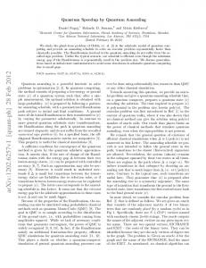
Figure 1: Schematic blueprint of a quantum processor based on quantum gates, represented here in the two-qubit case relevant for our experiment. A quantum processor consists of a qubit register that can perform any unitary evolution needed by an algorithm under the effect of a universal set of quantum gates (single qubit gate U1 , two-qubit gate U2 ). Ideally, all the qubits may be read projectively, and may be reset.
Since the Deutsch-Jozsa classification algorithm is not directly related to any practical situation, demonstrating quantum speed-up for more useful algorithms in an electrical processor designed along the blueprint of Fig. 1 is an important goal. In this work, we operate a new two transmon-qubit processor [13] that comes closer to the ideal scheme than those previously mentioned, and we run the Grover search algorithm among four objects. Since, in this case, the algorithm ideally yields the answer after one algorithm step, its success probability after a single run provides a simple benchmark. We find that our processor yields the correct answer at each run with a success probability that ranges between 0.52 and 0.67, whereas a single step classical algorithm using a random query would yield the correct answer with probability 0.25. The scheme and the operation mode of our processor is shown in Fig. 2. Two tunable transmon qubits coupled by a fixed capacitor, are embedded in two identical control and readout sub-circuits. The Hamiltonian of the �two qubits {I, II} is H/h = −νI σzI − νII σzII + 2gσyI σyII /2, where σx,y,z are the Pauli operators, νI,II the qubit frequency controlled by the flux applied to each transmon SQUID loop with a fast (0.5 GHz bandwidth) local current line, and g = 4.6MHz � νI,II the coupling frequency controlled by the coupling capacitance. The achieved fre-
2 (a)
readout I
qubit II
I0
20mK
qubit I
50 A
4K
LO ACQ
00, 01, 10, or 11
(b)
0
50
100
150
X12()
iSWAP
Y(/2)
iSWAP
Z(/2)
[t], a(t)
Y(/2)
readout
200 ns
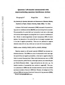
Figure 2: Electrical scheme of the two qubit circuit operated and typical sequence during processor operation. (a) Two capacitively coupled transmon qubits (green) have tunable frequencies controlled by the flux induced in their SQUID loop by a local current line (in red). The coupling capacitance (in magenta) yields a swapping evolution between the qubits when on resonance. Each transmon is embedded in a nonlinear resonator used for single-shot readout. Each reflected readout pulse is routed to a cryogenic amplifier through circulators, homodyned at room temperature and acquired digitally, which yields a two-bit outcome. (b) Typical operation of the processor showing the resonant microwave pulses a(t) applied to the qubits (green) and to the readouts (blue), on top of the DC pulses (red lines) that vary the transition frequencies of qubit I (solid) and II (dashed). With the qubits tuned at a first working point for single qubit gates, resonant pulses are applied for performing X and Y rotations, as well as small flux pulses for Z rotations; qubits are then moved to the interaction point for two-qubit gate operations. Such sequences can be combined as needed by the algorithm. Qubits are then moved to their initial working points for applying tomography pulses as well as a |1i → |2i pulse X12 (π) to increase the fidelity of the forthcoming readout. Finally, they are moved to better readout points and read.
quency control allows us to place the two transmons on resonance during times precise enough for performing the √ universal two-qubit gate iSW AP [13] and the exchange gate iSW AP used in this work. The qubit frequencies are tuned to different values for single qubit manipulation, two-qubit gate operation, and readout. The readout is independently and simultaneously performed for each qubit using the single-shot method of Ref. [14]. It is based on the dynamical transition of a non-linear resonator [15, 16] that maps the quantum state of each transmon to the bifurcated/non bifurcated state of its resonator,
which yields a binary outcome for each qubit. This readout method is potentially non-destructive, but its nondestructive character is presently limited by relaxation during the readout pulse. In order to further improve the readout fidelity, we resort to a shelving method that exploits the second excited state of the transmon. For this purpose, a microwave pulse that induces a transition from the state |1i towards the second excited state |2i of the transmon is applied just before the readout pulse as demonstrated in Ref. [14]. This variant does not alter the non-destructive aspect of the readout method since an extra pulse bringing state |2i back to state |1i could be applied after readout. Although the readout contrast achieved with this shelving method and with optimized microwave pulses reaches 0.88 and 0.89 for the two qubits respectively, the values achieved at working points suitable for processor operation are lower and equal to 0.84 and 0.83. The readout outcome probabilities for all input states of the two-qubit register are given in the Supplementary Information S4, with a discussion of the error sources. In order to characterize the evolution of the quantum register during the algorithm, we determine its density matrix by state tomography. For this purpose, we measure the expectation values of the extended Pauli set of operators {σx I, .., σz σz } by applying the suitable rotations just before readout and by averaging typically 104 times. Note that the readout errors, which can be well-characterized, are corrected when determining the expectation value of the Pauli set, and thus do not contribute to tomography errors as explained in Ref. [13]. The density matrix ρ is then taken as the acceptable positive-semidefinite matrix that, according to the Hilbert-Schmidt distance, is the closest to the possibly non physical one derived from the measurement set. In order to characterize the fidelity of the algorithm at all steps, we use the state fidelity F = hψ |ρ| ψi with |ψi the ideal quantum state at the step considered; F is in this case the probability for the qubit register to be in state |ψi. The Grover search algorithm [1] consists in retrieving a particular basis state in a Hilbert space of size N using a function able to discriminate it from the other ones. This function is used to build an oracle operator that tags the searched state. Starting from the superposition |φi of all register states, a unitary sequence that √ incorporates the oracle operator is repeated about N times, and eventually yields the searched state with a high probability. The implementation of Grover’s algorithm in a two-qubit Hilbert space often proceeds in a simpler way [17–22] since the result is obtained with certainty after a single algorithm step. The algorithm then consists of an encoding sequence depending on the searched state, followed by a universal decoding sequence that retrieves it. Grover’s algorithm thus provides a simple benchmark for two-qubit processors. Its implementation with our
3 both from small unitary errors accumulated during the algorithm, and from decoherence during the whole sequence, in particular during the final readout.
preparation
|0>
Y( 2 )
|0>
Y( ) 2
readout
Grover algorithm
Z( ) 2 Z( )
iSWAP
(a)
iSWAP
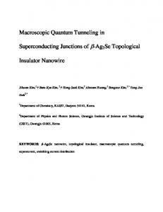
quantum processor is shown in Fig. 3(a). First, the superposed state |φi is obtained by applying π/2 rotations around the Y axis for the two qubits. The oracle operator Ouv tagging the two-qubit state |uvi ≡ |uiI ⊗ |viII to be searched is then applied to state |φi. Each Ouv consists of a iSWAP gate followed by a Z(±π/2) rotation on each qubit, with the four possible sign combinations (−, −), (+, −) , (−, +) , and (+, +) corresponding to uv = 00, 01, 10, and 11, respectively. In the algorithm we use, as in Ref. [10], the encoding is a phase encoding. When applied to |φi, each oracle operator inverts the sign of the component corresponding to the state it tags, respectively to the other ones. The density matrix after applying the oracle ideally takes a simple form: the amplitude of all coefficients is 1/4, and the phase of an element ρrs is ϕrs = π(δrt + δst ), where t corresponds to the state tagged by the oracle operator. The state tomography performed after applying the oracle, shown in Fig. 3(b), is in good agreement with this prediction. More quantitatively, we find that after having applied the oracle operator, the intermediate fidelity is Fint = 0.87, 0.80, 0.84, and 0.82, respectively. The last part of the algorithm consists in transforming the obtained state in the searched state irrespectively of it, or equivalently to transform the phase information distributed over the elements of the density matrix in a weight information with the whole weight on the searched state. This operation is readily performed by applying an iSWAP gate followed by Y (π/2) rotations on each qubit. We find that the fidelity of the density matrix at the end of the algorithm is Ffinal = 0.70, 0.62, 0.67, and 0.66 respectively. We explain both Fint and Ffinal by gate errors at a 2% level, by errors in the tomography pulses at a 2% level, as well as by decoherence during the whole experimental sequence (at the coupling point, relaxation times are T1I ' 450 ns and T1II ' 500 ns, and the effective dephasing times TϕI ' TϕII ' 2 µs [13]). Ffinal is thus approximately the success probability one would obtain assuming no errors when reading the qubit register at the end of the algorithm. We now consider the success probability obtained after a single run (with no tomography pulses), which probes the quantum speed-up actually achieved by the processor. We find (see Fig. 3) that our processor does yield the correct answer with a success probability PS = 0.67, 0.55, 0.62, and 0.52 for the four basis states, which is smaller than the density matrix fidelity Ffinal . One notices that the difference between Ffinal and PS , mostly due to readout errors, slightly depends on the searched state: the larger the energy of the searched state, the larger the difference. This dependence is well explained by the effect of relaxation during the readout pulse, which is the main error source at readout, the second one being readout crosstalk. One also notices that the outcome errors are distributed over all the wrong answers. To summarize, the error in the outcome of Grover’s algorithm originate
2
Y( )
0
1
Y( ) 2
0
1
2
tomography
oracle
single run
(b) |00>
0.67
0.70
|01> |10> |11>
0.55
0.62
0.62
0.67
0.66
0.52
Figure 3: (a) Experimental sequence used for implementing the Grover search algorithm on four objects. First, Y (π/2) rotations are applied to produce the superposition P |φi = (1/2) u,v |uvi of all basis states; then one of the four possible oracle (corresponding to the four sign combinations of the Z rotations) is applied. The tagged state is then decoded in all cases using a iSW AP operation followed by Y (π/2) rotations. (b) State tomography at two steps of the algorithm and success probability after a single run. The yellow dot on the left marks the basis state tagged by each oracle operator used. After applying the oracle, the information on the tagged state is encoded in the phase of six particular elements of the density matrix ρ. After decoding, the tagged state should be the only matrix element present in ρ. The amplitude of each matrix element is represented by a disk (black for the ideal density matrix, red for the measured one) and its phase by a radius (as well as a filling color for the ideal matrice). The probability distribution of the single-run readout outcomes is indicated on the right (yellow box for the correct answer, filled dark boxes for the wrong ones).
4 We now discuss the significance of the obtained results in terms of quantum information processing. The achieved success probability is smaller than the theoretically achievable value 1, but nevertheless sizeably larger than the value of 0.25 obtained by running once the classical algorithm that consists in making a random trial. From the point of view of a user that would search which unknown oracle picked at random has been given to him, the fidelity of the algorithm outcome is Fo = 0.57, 0.63, 0.57, and 0.59 for the 00, 01, 10, and 11 outcomes respectively, as explained in the Supplementary Information S5. Despite the presence of errors, this result demonstrates the quantum speed-up for Grover’s algorithm when searching in a √ Hilbert space with small size N = 4. Demonstrating the N speed-up for Grover’s algorithm in larger Hilbert spaces requires a qubit architecture more scalable than the present one, which presently is a major challenge in the field. In conclusion, we have demonstrated the operation of the Grover search algorithm in a superconducting twoqubit processor with single-shot non destructive readout. This result indicates that the quantum speed-up expected from quantum algorithms is within reach of superconducting quantum bit processors.
[1] L.K. Grover, Proceedings, 28th Annual ACM Symposium on the Theory of Computing, 1996, p. 212; and Am. J. Phys., 69, 769 (2001).
[2] P.W. Shor, Proceedings, 35th Annual Symposium on Foundations of Computer Science, IEEE Press, Los Alamitos, CA, (1994); and SIAM J. Comp., 26, 1484, (1997). [3] M. A. Nielsen and I. L. Chuang, Quantum Computation and Quantum Information (Cambridge University Press, Cambridge, UK, 2000). [4] T.D. Ladd et al., Nature 464, 45 (2010). [5] D.P. DiVincenzo, Fortschritte der Physik 48, 771-784 (2000). [6] J. Koch et al., Phys. Rev. A 76, 042319 (2007). [7] J.A. Schreier et al., Phys. Rev. B77, 180502 (2008). [8] Y. Nakamura, Yu. A. Pashkin, and J. S. Tsai1, Nature 398, 786 (1999). [9] D. Deutsch and R. Jozsa, Proc. R. Soc. London 1A, 439, 553 (1992). [10] L. DiCarlo et al., Nature 467, 574 (2010). [11] T. Yamamoto et al., Phys. Rev. B 82, 184515 (2010). [12] M. Mariantoni et al., Science DOI:10.1126, (2011); arXiv:1109.3743. [13] A. Dewes et al., submitted to Phys. Rev. Lett; arXiv:1109.6735. [14] F. Mallet et al., Nature Physics 5, 791 (2009). [15] I. Siddiqi et al., Phys. Rev. Lett. 93, 207002 (2004). [16] M. Metcalfe et al., Phys. Rev. B 76, 174516 (2007). [17] J.A. Jones, M. Mosca, and R.H. Hansen, Nature 393, 344 (1998). [18] I.L. Chuang, N. Gershenfeld, and M. Kubinec, Phys. Rev. Lett. 80, 3408 (1998). [19] K.A. Brickman et al., Phys. Rev. A 72, 050306, (2005). [20] N. Bhattacharya et al., Phys. Rev. Lett. 88, 137901 (2002). [21] P. Walther et al., Nature 434, 169 (2005). [22] J. Ahn, T.C. Weinacht, and P.H. Bucksbaum, Science 287, 463 (2000).
Supplementary material
S1. Sample preparation The sample is fabricated on a silicon chip oxidized over 50 nm. A 150 nm thick niobium layer is first deposited by magnetron sputtering and then dry-etched in a SF6 plasma to pattern the readout resonators, the current lines for frequency tuning, and their ports. Finally, the transmon qubit, the coupling capacitance and the Josephson junctions of the resonators are fabricated by double-angle evaporation of aluminum through a shadow mask patterned by e-beam lithography. The first layer of aluminum is oxidized in a Ar − O2 mixture to form the oxide barrier of the junctions. The chip is glued with wax on a printed circuit board (PCB) and wire bonded to it. The PCB is then screwed in a copper box anchored to the cold plate of a dilution refrigerator. S2. Sample parameters The sample is first characterized by spectroscopy (see Fig. 1.b of main text). The incident power used is high enough to observe the resonator frequency νR , the qubit line ν01 , and the two-photon transition at frequency ν02 /2 between the ground and second excited states of each transmon (data not shown). A fit of the transmon model I to the data yields the sample parameters EJI /h = 36.2 GHz, EC /h = 0.98 GHz, dI = 0.2, EJII /h = 43.1 GHz, II I II EC /h = 0.87 GHz, dII = 0.35, νR = 6.84 GHz, and νR = 6.70 GHz. The qubit-readout anticrossing at ν = νR yields the qubit-readout couplings g0I ' g0II ' (2π) 50 MHz. Independent measurements of the resonator dynamics (data I II not shown) yield quality factors QI = QII = 730 and Kerr non linearities [13,[1]] KI /νR ' KII /νR ' −2.3±0.5×10⁻⁵ . S3. Experimental setup • Qubit resonant microwave pulses: The qubit drive pulses are generated by two phase-locked microwave generators feeding a pair of I/Q-mixers. The IF inputs are provided by a 4-Channel1 GS/s arbitrary waveform generator
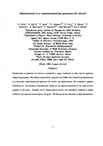
5 (AWG Tektronix AWG5014). Single-sideband mixing in the frequency range of 50-300 MHz is used to generate multi-tone drive pulses and to obtain a high ON/OFF ratio (> 50 dB). Phase and amplitude errors are corrected by applying suitable sideband and carrier frequency dependent corrections to the amplitude and offset of the IF signals. • Qubit frequency control: Flux control pulses are generated by a second AWG and sent to the chip through a transmission line equipped with 40 dB total attenuation and a pair of 1 GHz dissipative low-pass filters at 4 K. The input signal of each flux line is returned to room temperature through an identical transmission line and measured, which allows to compensate the non-ideal frequency response of the line. • Readout pulses: The driving pulses for the Josephson bifurcation amplifier (JBA) readouts are generated by mixing the continuous signals of a pair of microwave generators with IF pulses provided by a 1 GS/s arbitrary waveform generator (AWG Tektronix AWG5014). Each readout pulse consists of a measurement part with a rise time of 30 ns and a hold time of 100 ns, followed by a 2 µs long latching part at 90 % of the pulse height. • Drive and measurement lines: The drive and readout microwave signals of each qubit are combined and sent to the sample through a pair of transmission lines with total attenuation 70 dB and filtered at 4 K and 300 mK. A microwave circulator at 20 mK protects the chip from the amplifier noise. The signals are amplified by 36 dB at 4 K by two cryogenic HEMT amplifiers (CIT Cryo 1) with noise temperature 5 K. The reflected readout pulses are amplified and demodulated at room temperature. The IQ quadratures of the demodulated signals are sampled at 1 GS/s by a 4-channel data acquisition system (Acqiris DC282). S4. Readout Errors Errors in our readout scheme are discussed in detail in Ref. [13] for a single qubit. First, incorrect mapping |0i → 1 or|1i → 0 of the projected state of the qubit to the dynamical state of the resonator can occur, due to the stochastic nature of the switching between the two dynamical states. As shown in Fig. S4.1, the probability p to obtain the outcome 1 varies continuously from 0 to 1 over a certain range of drive power Pd applied to the readout. When the shift in power between the two p|0i,|1i (Pd ) curves is not much larger than this range, the two curves overlap and errors are significant even at the optimal drive power where the difference in p is maximum. Second, even in the case of non overlapping p|0i,|1i (Pd ) curves, the qubit initially projected in state|1i can relax down to |0i before the end of the measurement, yielding an outcome 0 instead of 1. The probability of these two types of errors vary in opposite directions as a function of the frequency detuning ∆ = νR − ν > 0 between the resonator and the qubit, so that a compromise has to be found for ∆. As explained in the main text, we � use a shelving method to the second excited state in order to improve the readout contrast c = M ax p|1i − p|0i , with a microwave π pulse at frequency ν12 bringing state |1i into state |2i just before the readout pulse. The smallest errors e0I,II and eI,II when reading |0i and 1 |1i are found for ∆I = 440 MHz and ∆II = 575 MHz: eI0 = 5% and eI1 = 13% (contrast cI = 1 − eI0 − eI1 = 82%), and II I I eII 0 = 5.5% and e1 = 12% (cII = 82%). When using the |1i → |2i shelving before readout, e0 = 2.5% and e2 = 9.5% I I II II (contrast cI == 1 − e0 − e2 = 88%), and e0 = 3% and e2 = 8% (cII = 89%). These best results are very close to those obtained in [12], but cannot however be exploited for simultaneous readout of the two qubits. Indeed, when the two qubits are measured simultaneously, we find an influence of the projected state of each qubit on the outcome of the readout of the other one. In order to to minimize this spurious effect, we increase the detuning ∆I,II up to ∼ 1 GHz with respect to previous optimal values. An immediate consequence shown in Fig. S4.1(a) is a reduction of the cI,II contrasts. The errors when reading |0i and |1i are then eI0 = 10 % and eI1 = 16 % (contrast II cI = 74%) and eII 0 = 12 % and e1 = 15 % (contrast cII = 73%). When shelving the qubit in state |2i , the errors are II I I e0 = 5 %, e2 = 11 % (contrast cI = 84%), eII 0 = 5 %, e2 = 12 % (contrast cI = 83%). The readout errors are captured in the 4 × 4 readout matrix R shown in Fig. S4.1(c), that gives the probabilities puv of the four possible outcomes for the different input states using the |1i → |2i shelving technique. This matrix R is used to correct the readout errors only when doing state tomography, and not when the running the algorithm once. The cause of the readout crosstalk in our processor is discussed in Ref. [11]. S5. Algorithm Fidelity The fidelity of each possible outcome ab ∈ {00, 01, 10, 11} of our algorithm is given as � fab = pab/|abi / pab/|00i + pab/|01i + pab/|10i + pab/|11i , where pab/|uvi is the conditional probability for obtaining ab when the state |uvi has been marked by the oracle Ouv . Table I shows these probabilities pab/|uvi for all possible combinations of ab and |uvi as well as the fidelities fab . The average fidelity of the algorithm is 59.1 %.
6 a) |2> |1> |0>
readout 2
switching probability p
0,8
readout 1
1,0 |2> |1>
|0> 0,6
0,4
0,2
0,0 -5
b)
-4
|00>
-3 -3 power [dB]
|01>
-2
|10>
|11>
00
01
10
11
Figure 4: (a) Switching probability p of each readout as a function of its peak driving power, when its qubit is prepared in state |0i (blue), |1i (red), or |2i (brown), with the other qubit being far detuned. The arrows indicate the readout errors where the contrast is optimal with (brown) and without (red) |1i → |2i shelving. (b) Readout matrix giving the probabilities of the four ab outcomes, for the four computational input states |uvi, when using |1i → |2i shelving.
ab/|uvi |00i 00 01 10 11
0.666 0.127 0.128 0.079
|01i
|10i
|11i
P
0.192 0.554 0.106 0.148
0.188 0.071 0.615 0.126
0.122 0.122 0.239 0.517
1.168 0.874 1.088 0.870
fab 57.0 63.4 56.5 59.4
% % % %
Table I: Conditional probabilities pab/|uvi and statistical fidelities fab for all possible outcomes ab, measured for our version of Grover’s algorithm.
[1] F. R. Ong et al., Phys. Rev. Lett. 106, 167002 (2011).