IEEE TRANSACTIONS ON CIRCUITS AND SYSTEMS—I: REGULAR PAPERS, VOL. 55, NO. 10, NOVEMBER 2008
3259
Demonstration of Uncoordinated Multiple Access in Optical Communications Herwin Chan, Member, IEEE, Andres I. Vila Casado, Student Member, IEEE, Juthika Basak, Member, IEEE, Miguel Griot, Student Member, IEEE, Wen-Yen Weng, Richard Wesel, Senior Member, IEEE, Braham Jalali, Fellow, IEEE, Eli Yablonovitch, Fellow, IEEE, and Ingrid Verbauwhede, Senior Member, IEEE
Abstract—Though it promises high bandwidths, the optical medium is not popular in local area networks. This is because current optical networks do not offer the ease of use and setup that an uncoordinated multiple access network such as Ethernet offers. In this paper, we propose a novel nonlinear trellis code designed for multiple access among uncoordinated nodes in an optical communications system. This code has been shown to have an efficiency of 30%. We have implemented the codes on Xilinx FPGA’s for a 6 user optical system, transmitting data on a single wavelength. The above system was set up using commercial off-the-shelf components and we demonstrated BER of < 1009 for three users, each running at a channel rate of 2 Gbps. Demonstration of this system required the design of new channel codes, architectural optimizations for the implementation of the channel codes for high speed with limited resources and electrical/optical optimizations to realize the optical channel. Index Terms—High-speed architectures, multiple access network, nonlinear trellis code, optical network, uncoordinated access network.
I. INTRODUCTION PTICAL communications have been becoming more and more important with the ever-increasing demands for bandwidth. Fiber optic technology has been demonstrated for speeds up to hundreds of gigabits per second because of its low loss and low dispersion over extended bandwidths. These properties of optical technology have been well utilized to form the backbone of global networks such as the internet and telephone networks.
O
Manuscript received January 9, 2007; revised December 1, 2007. First published April 18, 2008; current version published November 21, 2008. This work was supported by the Space and Naval Warfare Systems Center—San Diego under Contract N66001-02-1-8938. This paper was recommended by Associate Editor A. Apsel. H. Chan is with Broadcom Corporation, San Diego, CA 92127 USA (e-mail:
[email protected]). A. I. Vila Casado, M. Griot, R. Wesel, and B. Jalali are with the Electrical Engineering Department of University of California, Los Angeles, CA 90095 USA (e-mail:
[email protected];
[email protected];
[email protected];
[email protected]). J. Basak is with the Photonics Technology Laboratory, Intel Corporation, Santa Clara, CA 95054 USA. W.-Y. Weng is with the Department of Computer Science and Information Engineering, Chung Hua University, Hsinchu 200, Taiwan (e-mail: wenyen.
[email protected]). E. Yablonovitch is with the Electrical Engineering Department, University of California, Berkeley, CA 94720 USA (e-mail:
[email protected]). I. Verbauwhede is with the Electrical Engineering Department, University of California, Los Angeles, CA 90095 USA, and also with Katholieke Universitiet, 3001 Leuven, Belgium (e-mail:
[email protected]). Digital Object Identifier 10.1109/TCSI.2008.925365
In the local area network domain, optical networks have had limited success. Though the optical token ring (FDDI) network promises higher bandwidth [1], Ethernet networks are significantly more popular. This success is due to the ease in which a network can be set up. Nodes on the network can be added and removed from the network dynamically without disruption of network communications. In addition, there is no coordination between the nodes. When a certain node wants to transmit data, it merely starts to transmit and the CSMA/CD protocol determines what to do when a collision occurs. This need not be the case. In the CANbus network [2], collisions between data from several transmitters are used to determine the priority of the messages. By monitoring the aggregate signal of all the transmitters, a transmitter can determine whether there is a transmitter of higher priority. If this is the case, it would abort its own transmission. High priority transmissions have higher number of dominant bits (bits whose value cannot be overwritten) in its header; if a dominant bit is detected by a transmitter that is transmitting a nondominant bit, then it knows that it is colliding with a high priority transmission. Though CANbus only allows collisions in the header of a data transmission to determine priority, it illustrates that data can be transmitted in the OR channel even when collisions occur. Though there are efforts to implement Ethernet on optical networks, aggregate throughput performance is fundamentally limited by collision of data [3]. The average throughput depends on many factors, the most important being the number of hosts (or users) and the distribution of the transmitted packet lengths. According to [3], for most cases the throughput ranges between 70% and 90%. However, the main disadvantage of the most common forms of uncoordinated multiple access channels, such as Aloha, slotted Aloha, carrier-sense CSMA, and CSMA with collision detection (Ethernet), is that they do not provide a clear QoS in terms of delay or delay jitter, since there can be collisions, and in case of collision the data packets need to be retransmitted. There is no guaranteed maximum number of retransmissions before a successful one in that case. This technology is therefore not suitable for applications such as VoIP or HDTV, where delay constraints are crucial. Due in part to these issues, the 1G Ethernet and 10G Ethernet standards have since removed support for uncoordinated access and have concentrated on point-to-point links. A common form of multiple access that can provide QoS in terms of delay and jitter is time-division multiple-access (TDMA). Optical TDMA as a form of multiple access in passive optical networks (PON) is currently commercially available. Ignoring overhead due to slot allocation, TDMA can
1549-8328/$25.00 © 2008 IEEE Authorized licensed use limited to: Univ of Calif Los Angeles. Downloaded on December 3, 2008 at 14:35 from IEEE Xplore. Restrictions apply.
3260
IEEE TRANSACTIONS ON CIRCUITS AND SYSTEMS—I: REGULAR PAPERS, VOL. 55, NO. 10, NOVEMBER 2008
theoretically have an efficiency of 100%. However, TDMA requires centralized network control. O-TDMA systems also suffer from bandwidth limitations and difficult scalability. More recently, optical code-divison multiple-access (O-CDMA) has been considered as an alternative due to its enhanced flexibility and simplicity of management since it does not require centralized network control. O-CDMA systems can support either synchronous or asynchronous traffic. Although the synchronous case provides better spectral efficiency, it requires chip-wise and bit-wise global synchronization increasing the complexity [4], [5]. An asynchronous O-CDMA has been proposed in [6]. In that work an asynchronous OCDMA system using 2–D time/wavelength coding with code position modulation (CPM) is demonstrated. A first implementation provides multiple access to six users transmitting at a data-rate 2.5 Gbits/s per user over eight wavelengths supporting a transmission of 10 Gchips/s/wavelength. This , gives an efficiency of around 19%. A similar CPM-2PPM implementation is described with better bit/chip efficiency. This implementation provides multiple access to eight users transmitting at a data-rate 10 Gbits/s per user over 12 wavelengths supporting a transmission of 24 Gchips/s/wavelength. The efficiency of this . system is The system proposed in this work provides an asynchronous and uncoordinated multiple-access, and given a certain number of users, the rate and delay for each user is specified. We demonstrate the desirable properties of Ethernet by marrying the highbandwidth properties of optical networks with the flexibility of Ethernet. Collisions are allowed, and corrected by careful design of forward-error correcting channel codes. The uncoordinated multiple access properties will be provided by a set of novel channel codes, which guarantee that data can be decoded . This BER at optical bit error rates (BERs), i.e., BER performance will be maintained even in the presence of other transmissions (interference). We model the optical channel as an OR multiple access channel. An OR channel behaves like an N-input OR gate, where N is the number of nodes transmitting simultaneously. Assuming on-off keying, if any node transmits a “1’ data bit, all the receivers will see a “1” bit in the channel. If all nodes transmit a “0” bit, then the receivers will see a “0” in the channel. In the CANbus network, the “1” bit is called the dominant bit since its value hides the presence of any “0” bits. A passive optical star network can also be used as an OR channel. Physically, the dominant “1” bit is represented by the presence of light and the “0” bit is presented by the absence of light. Theoretically, up to 70% efficiency can be achieved in such a channel by treating the interference of other users as noise. In [7] nonlinear turbo codes which provide a BER of 1e-7 at 60% efficiency has been proposed. However, these codes require block-lengths in the order of thousands, which increases latency, and require an iterative decoding which is costly to implement and cannot achieve the required throughput for optical speeds using current technology. We are able to achieve 30% efficiency by using nonlinear trellis codes, which can be decoded using the Viterbi [8] algorithm, which has low complexity and provides the throughput required in this application. The system
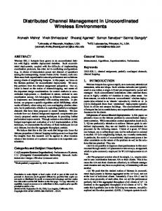
Fig. 1. High-level view of demonstration system.
shown in this work allows a completely uncoordinated multiple access, which provides a fixed throughput efficiency (30%) and a fixed delay given the number of users. This efficiency is similar or better than the shown in [6] without the need of CPM. Note that the CPM provides improved efficiency at the cost of a receiver that needs to operate at the chip rate instead of the bit rate. Although this comparison does not consider how implementation scales to high number of users, encoder/decoder complexity, or bit-rate, it shows that our system can outperform asynchronous OCDMA in terms of efficiency. This is due to the use of FECs to treat collisions, which are avoided in present O-CDMA solutions. A. Demonstrator Design This paper describes the design and implementation of a system that demonstrates an uncoordinated multiple access optical network. The system features six nodes simultaneously transmitting into an optical channel. A receiver node takes the aggregate signal and decodes a single user. Fig. 1 shows the system block diagram of our system. Each transmitting node is comprised of an FPGA, which codes the data; a laser, which provides the carrier for the coded data; and a modulator, which combines the two together and puts the data on the channel. The goal of our demonstration system is to show successful transmission and decoding of data from six users on a single optically coupled network. The channel bit rate of 2 Gbps is divided among the 6 nodes using novel channel coding techniques. This will give an uncoded useful data bandwidth of 93 Mbps for each node. The channel bandwidth is guaranteed for each node; in Ethernet technologies, useful bandwidth experienced by each node are not guaranteed and depends on the traffic characteristics of the other nodes in the system. Though the system was built with commercial off the shelf components, the design involves close cooperation between several design domains. The decision to implement the channel codes on a Virtex II Pro FPGA platform allows hardware speeds to be achieved while maintaining a programmable platform. In addition to this, this platform allows us to accurately predict the performance and cost of such a network in the future when ASICs are used. However, the choice of platform also imposes limitations on the other two domains. The Virtex II Pro FPGA board contains several high speed serial transceivers. They were independently measured to be able
Authorized licensed use limited to: Univ of Calif Los Angeles. Downloaded on December 3, 2008 at 14:35 from IEEE Xplore. Restrictions apply.
CHAN et al.: UNCOORDINATED MULTIPLE ACCESS IN OPTICAL COMMUNICATIONS
to support a channel rate of 2 Gbps. The electrical/optical system was built in order to support this rate. The main design goal for channel coding is to find the highest BER. Experience rate code that is able to provide has shown to us that for complex FPGA designs, useful work takes between 5 to 10 ns to compute (from the datasheet, a 64 bit accumulator takes 6.7 ns and does not include the routing overheads of a large design); this translates to a 100 to 200 MHz clock. In order to process the 2 Gbps, the coding algorithm will need to support a parallelization factor of at least 10 to 20. Also because of the large throughput requirements, powerful iterative coding algorithms may not be used. The Sections II–V discuss in detail the design issues in each of the three design domains and how they interact with each other. Section II describes the design process of the channel code. Section III describes how these algorithms were implemented onto a FPGA platform. Section IV describes the optical system and how the logical system interfaces with it. Section V analyzes the results of the final demonstration system setup and Section VI concludes the paper. II. UNCOORDINATED MULTIPLE ACCESS STRATEGY In this section, we present a review of the optical channel model used in this work and the high-level system design techniques used to provide uncoordinated multiple access to optical channels. For further details on the theoretical aspects of the approach presented in this paper, the reader should look at [9]. A simple communications model that can describe the multiple-user optical channel with noncoherent combining is the OR multiple access channel (OR-MAC). In this channel, if all users transmit a zero, then the channel output is a zero. However, if even one user transmits a one, then the channel output is a one. Information theory tells us that the maximum sum-rate (the sum of the rates of all the transmitters in the system) of the OR channel is 1 information bit per received data bit. For uncoordinated multiple-access, interleaver-division multiple-access (IDMA) [10], [11] is a promising approach which has been successfully applied to general MACs. With IDMA, every user has the same channel code, but each user’s code bits are permuted using a unique randomly drawn interleaver. The receiver is assumed to know the interleaver of the desired users, and performs joint iterative decoding of all the users data. However, under current technology, this decoding technique produces prohibitively large designs for optical speeds with today’s technology. Hence, for a simple uncoordinated access decoder, other users must be treated as noise. From a single-user perspective, this transforms the OR channel into the Z-Channel shown in Fig. 2. In this channel, when a particular user transmits a 1, a 1 is received. When this user transmits a 0, a 1 can be received with probability equal to the probability that any of the users transmits a 1. Treating other users as noise, a channel sum-rate of can theoretically be achieved for any number of users. Thus, while dramatically decreasing the decoding complexity, only 30% of the channel sum-rate would be lost with the use of capacity achieving codes.
3261
Fig. 2. The Z-Channel.
For the IDMA-based architecture presented above, what is left is to design appropriate channel codes for the Z-Channel. In order to achieve the maximum symmetric sum-rate where each user sees a Z-channel, the channel code must produce in its output a particular average density of ones which depends on the number of users as
Linear codes produce an average ones density of 1/2, which would lead to an unacceptable sum-rate. For example, for 6 users the maximum achievable sum-rate using linear codes is less than 10%, and for 10 users it is less than 1%. Hence, nonlinear codes that produce the proper ones density are required for this application. The channel code used in this work is a nonlinear trellis code (NL-TC) code. This novel code provides the appropriate information rate and density of ones. A Viterbi decoder allows a simple and fast decoding of NL-TC. A brief description of the design of these codes is presented in Sections II-A–C. A. Directional Hamming Distance Regular convolutional codes are designed so that the Hamming distance between codewords is maximized. Hamming distance is the number of bits that differ between the codewords. This distance is directly associated with the number of errors such a code can decode. In the Z-Channel, a transmitted 1 will always induce a received 1. Thus, to make a decoding error, the decoder must see ones in all the bit positions where the incorrect codeword has ones. This implies that a new definition of distance is required. Let us define the directional Hamming distance the number of positions at which the codeword has a 0 and the codeword has a 1. Note that is not necessarily equal to . Given that the purpose of the design is to maximize this directional distance, the safest definition of distance between branches would be
which is the “greedy” branch-wise metric that will be maximized in our design. By taking the minimum between the two directional distances as the metric to maximize, we seek to maxbetween all codeimize the minimum directional distance words, albeit in a greedy fashion. With this branch-wise metric, codewords with equal Hamthan codewords with difming weights produce a larger ferent Hamming weights, so we will assign output values to the trellis branches with as similar Hamming weight as possible, preferably equal.
Authorized licensed use limited to: Univ of Calif Los Angeles. Downloaded on December 3, 2008 at 14:35 from IEEE Xplore. Restrictions apply.
3262
IEEE TRANSACTIONS ON CIRCUITS AND SYSTEMS—I: REGULAR PAPERS, VOL. 55, NO. 10, NOVEMBER 2008
Fig. 3. Basic subgraph of the trellis diagram.
Fig. 4. (a) Four paths that start on the same state in two trellis sections. (b) Four paths that arrive to the same state in two trellis sections. Branches are labeled with the input bits that induce traversal of the branch.
B. Nonlinear Trellis Code Design We use a conventional feed-forward trellis encoder in order to determine the branches of the trellis, as shown in Fig. 3. It is a rate-1/n, -state trellis code, with one input bit per trellis branch. However, instead of using generator polynomials to compute the output of each branch as is typically done, a nonlinear table-lookup directly assigns the output values. The trellis code design consists of assigning output values to the branches of the trellis code. Those outputs have to maintain the desired average density of ones . Our goal is to maximize using the greedy pairthe minimum directional distance wise metric. The first step in the design is to assign the Hamming weight of each branch (number of ones), so that the optimal average ones density is satisfied as closely as possible. What is left is to assign the position of those ones in each of the outputs. An extension of Ungerboeck’s rules [9] in the context of our pairwise metric can be applied. Ungerboeck’s rule [12] is based on the fact that every incorrect codeword, in its trellis representation, departs from the correct state (split) at some trellis section and returns to the correct state (merge) at least once. Ungerboeck’s rule consists on maximizing the distance between branches splitting from a state (splits) and branches merging to a same state (merges). One can extend Ungerboeck’s rule more deeply into the trellis, and maximize not only the distance between splits, and the distance between merges, but the distance between the four branches coming from a split in the previous trellis section, or the 8 branches coming from a split two sections before, and so on (see Fig. 4). One can do the same with the merges moving backwards in the trellis. Notice that by maximizing the distance between the eight branches coming from a split two sections before, we are also maximizing the distance between all four branches coming from a split a trellis section before, and all splits. The same design strategy is used to maximize the distance between merges.
Fig. 5. BER of NL-TC codes versus the number of users.
Using the above design strategy, three candidate codes were design with coding rates of 1/17, 1/18, and 1/20. Fig. 5 shows the candidate codes in a Matlab simulation of BER versus the number of simultaneous users in the system. The achieved BER is in the order 1e-5 which is considerably above our target BER 1e-9. However, this can be solved by using a Reed–Solomon code as an outer-code as will be explained in Section III. The 1/20 code was chosen for our system for practical reasons. Though the 1/17 and 1/18 codes may achieve the required BER, the high speed serial transceiver has a 20 bit interface and is, therefore, easier to connect with a 1/20 code. Simple masking of the interface for 17 or 18 bits is not possible since 20 bits is still transmitted at the output. The masked bits, though unused, still contribute to the waveform at the output. Therefore, non20 bit codes require extra interface hardware to be built and may add to the complexity of the design and decrease throughput. C. Block Code With NL-TC Optical systems typically deliver a very low BER. In order to maintain this BER, the rate of the NL-TC channel code would have to be very low. A better solution is found taking into account the distribution of the erred bits in a transmitted stream after the NL-TC decoding. Thus, a high rate block code that can correct few symbol errors can be attached as an outer code, dramatically lowering the BER. A concatenation of the rate-1/20 NL-TCM code with a (255 bytes, 237 bytes) Reed–Solomon code has been tested for the 6-user OR-MAC scenario. The rate of this code is . The simulated BER is 2.5e-10. For six users, the sum-rate is . III. CODE IMPLEMENTATION The coding algorithms were implemented on the Xilinx VirtexII-Pro FPGA [13]. In particular, we implemented a rate-1/20 64-state NL-TC, intended for 6-user multiple access to the OR channel. The implementation dataflow block diagram is shown in Fig. 6. Data to be transmitted is first encoded with a Reed Solomon block code. The output bits of this block are encoded with the trellis code and then passed on to the
Authorized licensed use limited to: Univ of Calif Los Angeles. Downloaded on December 3, 2008 at 14:35 from IEEE Xplore. Restrictions apply.
CHAN et al.: UNCOORDINATED MULTIPLE ACCESS IN OPTICAL COMMUNICATIONS
3263
Fig. 7. Trellis encoder architecture.
Fig. 6. Coding implementation dataflow.
interleaver. Finally, the resulting bits are sent to the high speed serial transceiver (Rocket I/O) to be sent off-chip. The chosen rate 1/20 trellis code together with IDMA provide the uncoordinated access properties of our system and are able to bring the BER to about 1e-5 for six users. The outer Reed Solomon block code further decreases the BER to below 1e-9. All the nodes of the system use the same code, but the IDMA interleavers are used to ensure that the coded bit patterns do not look the same in the optical channel. Finally, the Reed–Solomon block code is used to further reduce the BER to less than 1e-9. In addition to these blocks, synchronization blocks ensure that the received bits are aligned properly so that decoding can be performed correctly. During code design, the interference signal was assumed to have a random uniform distribution; therefore interleavers are used after channel coding to randomize the position of the code bits. This combination allows us to recover data at a BER of 1e-5. A Reed Solomon block code is added at the back end to reduce the BER further to 1e-9. Since our target physical layer is the optical channel, data throughput is the main design criterion. The Viterbi decoder and interleaver blocks have been identified as the bottlenecks of the system and novel architectures are developed to mitigate their effects. A. Trellis Encoder To protect data in the OR channel, our NL-TCM code uses 20-bit codewords and contains 64 states. Fig. 7 shows the architecture of the trellis encoder. The design of the encoder consists of a 5–bit shift register used to address memories that outputs two of the 128 possible codewords. The latest input bit is used to select the desired codeword. Each clock cycle a new data bit is shifted into the register and a new 20–bit codeword is produced. Unlike common binary encoders, our trellis code has a relatively low ones density, much less than the usual 50%. B. Viterbi Decoder In DSP implementations, the Viterbi decoder focused on the acceleration of a single branch metric calculation and careful memory management for storing the results. This means for decoding a single code word, several clock cycles (depending on
Fig. 8. Viterbi decoder architecture.
the number of states in the trellis code) are needed. Hardware architectures such as those proposed by Zhu and Benaissa [14] and Guo et al. [15] have focused on area efficient architectures. For common wireless applications, such as 802.11b and 802.16a, Abdul Shakoor [16] describe a fast parallel hardware implementation that decodes at 160 Mbps on a FPGA. For our nonlinear trellis code that uses 20-bit codewords and contains 64 states, a traceback length of 35 is used in the Viterbi decoder. The technique used to design the decoder is to parallelize and pipeline all operations as much as possible. Care was taken to find structures where feedback paths are as short as possible. The overall architecture of the Viterbi decoder is shown in Fig. 8. The Viterbi decoder can be divided into several different stages, each of these stages will be discussed individually in detail: • calculation of metric; • accumulation and selection of metric; • finding of minimum path; • subtraction of accumulated result. 1) Branch Metric: Because the Viterbi decoder is being designed for the OR channel, the branch metric used is different from traditional designs. In an OR channel, it is impossible to receive a 0 bit when a 1 bit has been transmitted by any of the nodes. Because of this, in the comparison between the received codeword and branch codeword, if any of the received bits is 0 when a 1 is expected the branch metric is set to a maximum value of 20. Errors in which a 1 is received when a 0 is expected are summed together to give the branch metric in the normal case. The logic used to implement this function is shown in Fig. 9. In
Authorized licensed use limited to: Univ of Calif Los Angeles. Downloaded on December 3, 2008 at 14:35 from IEEE Xplore. Restrictions apply.
3264
IEEE TRANSACTIONS ON CIRCUITS AND SYSTEMS—I: REGULAR PAPERS, VOL. 55, NO. 10, NOVEMBER 2008
Fig. 9. Calculation of path metric.
two sets of sorted numbers into a single set is also recursive and based on the use of two input comparators. numbers, the number of comparaFor the sorting of . The delay through the network is tors grows in . For our system of 64 states, this translates to 543 comparators with a delay of 21 comparators. However, since there are no feedback paths in the sorting algorithm, the architecture can be fully pipelined to achieve very fast throughputs. 4) Subtraction of Accumulated Result: The minimum path metric is fed back to the Viterbi decoder and subtracted from all 64 accumulated path metrics. This is to ensure that the register values do not overflow. The sorting network used to find the minimum path is heavily pipelined, so the value used is several cycles behind the values that are currently calculated. This delay in the results translates to larger possible accumulated path metric values which may necessitate the use of larger operators (like adders); this increases the delay of the calculation. Therefore, care was taken to pipeline the sorting network only to the degree that is necessary to avoid unnecessary increases in hardware and possible increases in critical path delays. The sorting network in our design is pipelined to have six cycles of latency. C. Interleaver
Fig. 10. Block diagram of sorting network.
our 64 state codes, 128 branch metrics are calculated in parallel; the logic used to calculate this function constitutes one stage in our decoder pipeline. 2) Accumulation and Selection: There are two possible branches that lead to each of the 64 state nodes. The path with the smallest path metric (which is an accumulation of past branch metrics) is chosen as the most likely path that was taken to reach the node. Path metric calculation is performed by adding the path metric of the source nodes to their respective branch metrics. The two sums are then compared and the path with the lowest metric is selected. Sixty-four of these calculations are performed in parallel and constitutes a single stage in our pipeline. Further pipelining of this stage is impossible since the calculation of the path metric involves a feedback path from previous path metric calculations. Fig. 9 shows the implementation of this function. 3) Finding Minimum Path: The most likely bit that was transmitted is the bit at the head of the path with the lowest path metric. At each cycle, 64 path metrics are calculated and their respective paths are accumulated. A sorting network is used to select the path with the smallest accumulated metric. A minimum time sorting network based on Batcher’s odd-even merging algorithm [17] is used. This is a recursive algorithm that sorts a group of unordered numbers (Fig. 10) and contains the following three steps: • divide the numbers in to two groups; • sort the two groups of numbers separately; • odd-even merge the two groups of numbers. Since it is a recursive algorithm, the basic operation is a sorting of two numbers. This is implemented with a two input comparator. The odd-even merge procedure which combines
Interleavers, which permute the order of data bits, are commonly used to randomize the data stream and improve the performance of error correcting codes. In our system, each transmitter uses a unique interleaver pattern designed to protect a transmission from interference in an OR channel. This pattern is chosen from a set of patterns determined at design time to have good cross correlation properties. The role of the interleaver in our system is similar to its role in an IDMA system described by Ping et al. [11]. In that system, interleavers are used to distinguish nodes in a wireless CDMA system and increase channel capacity. The interleaver design, therefore, must be flexible enough to accommodate a family of permutation sequences that work well together. Interleaver design for IDMA has been examined by Pupeza [18]. In that work, however, the focus has been focused on performance efficiency rather than high-speed implementation. As a consequence, we are unable to take advantage of their results, instead, a novel new architecture was developed. A deinterleaver is used at the receiver to recover the initial sequence. Its architecture is the same as the interleaver architecture; the permutation sequences, however, are run in reverse order to recover the original uninterleaved signal. In theory, the ideal interleaver architecture is one that allows an input data block of size N to be permuted to any of its N! possible permutations. Conventional interleaver architectures process the data serially i.e., a single bit at a time. This scheme becomes increasingly difficult to implement as data rates increase e.g., a 10 Mbps channel only allows 100ps to process each bit. Our architecture design, therefore, focuses on parallel processing to achieve the desired rate. We took care, however, to ensure that the architecture can support enough permutations so that a good set of interleaver patterns can be found. One possible method of implementing the interleaver is to consider the input as 20 bit words. The output of the interleaver
Authorized licensed use limited to: Univ of Calif Los Angeles. Downloaded on December 3, 2008 at 14:35 from IEEE Xplore. Restrictions apply.
CHAN et al.: UNCOORDINATED MULTIPLE ACCESS IN OPTICAL COMMUNICATIONS
3265
TABLE I SIZE AND SPEED OF TRANSMITTER AND RECEIVER BLOCKS
Fig. 11. Indexed write-by-row, read-by-column interleaver.
will be a random ordering of the 20 bit words. The implementation of this interleaver is both fast and has low complexity. However, simulations show that this does not provide enough randomness for our channel codes. To increase randomness without sacrificing speed and complexity, we adopted a randomized write-by-row, read-by-column scheme for our 1600 bit interleaver. As seen in Fig. 11, data can be broken into square blocks of 400 bits. Each of the 20 rows and columns are indexed. Groups of 20 incoming bits are written to a randomly indexed row. When the data block is filled, the bits are read out of the block one column at a time in a random order. The 400-bit-square block forms the basic unit of our interleaver design. In order to produce the necessary randomness, four of such blocks were used in our final implementation. Like the indexing within the blocks, the inputs and outputs of the four blocks are accessed independently and randomly. This scheme provides us with enough randomness to operate on the optical channel. In our interleaver design, 4 square blocks of 400 bits are used, giving us a total of 80 indexed locations. possible This corresponds to a design space of permutation sequences to choose from. For the desired channel rate of 2 Gbps, using the 20-bit wordsize of our trellis code, our target operating frequency for the interleaver is 100 MHz. Two such memory blocks are used to allow the desired throughput to be maintained. While the first block is being written to, the second block is being read out. When the memory block is filled/emptied, the function of the memory blocks is reversed. This ping-pong arrangement doubles the area of the interleaver. D. Reed Solomon Code When the Trellis decoder block makes an error, the errors usually come in a burst of a few bits at a time. A Reed Solomon (RS) code is a block code that operates on bytes at a time. This makes it a very good choice to correct the residual errors and bring the final BER to below 1e-9. A standard (255,237) RS code was selected. Since timing is not critical in this block, a standard open source architecture design from Han [19] was used. The syndromes of the input data block are first calculated. The results are then used to calculate the error locator polynomial using Berlekamp’s algorithm. The Chien algorithm is used to find the roots of the error locator polynomial and these roots provide the
location of the errors. Finally, the magnitudes of the errors are captured. The data rate at the output of the NL-TCM decoder is 100 Mbps. Since the Reed Solomon code operates on data blocks of 255 bytes (2040 bits), the time budget for the RS decoder is 20.4 us. We clocked the module at 50 MHz, and at the worse case the decoding operation takes 856 cycles (17.1 s) to complete. E. Implementation Results The system blocks were implemented on the VirtexII-Pro FPGA from Xilinx. Table I summarizes the size various blocks in the design. The critical period is given for the transmitter and receiver. The transmitter is implemented on the VirtexII Pro XC2VP20 FPGA which contains 9,230 slices of logic. Each transmitter design occupies 40% of the available area. The receiver is a significantly larger design and is implemented on the XC2VP50 which has a capacity of 23,616 slices. The receiver design occupies 70% of the available area. IV. ELECTRICAL/OPTICAL SYSTEM Optical systems implementing wavelength division multiplexing (WDM) and Ultradense WDM with wavelength spacing as small as 0.05 nm (6.25 GHz) have been demonstrated to give a high level of multiplexing [17]. However, such systems require coordination between the different users to make sure that no two users transmit at the same wavelength. The multiple access scheme proposed in this paper, however, requires that there be no coordination. In addition, this scheme is independent of the center wavelength used for the optical transmission, unlike the requirement of specifically designed multiplexers/demultiplexers for WDM systems. The nonlinear trellis codes described and designed here are based on the assumption that there is incoherent addition of the data from the six channels. In other words, the transmission of a “1” from any two users cannot result in destructive interference and will always result in a “1.” In contrast, interference from two coherent sources may result in an output of “0.” In the implementation of our system, we use different laser sources for each channel, with wavelengths determined independently of each other. Hence, coupling of any two laser outputs can only give a “1” by constructive interference and never a “0.” The electrical/optical system design for the demonstration is shown in Fig. 12. Six independent continuous wave lasers, centered at 1550 nm are independently modulated with data from
Authorized licensed use limited to: Univ of Calif Los Angeles. Downloaded on December 3, 2008 at 14:35 from IEEE Xplore. Restrictions apply.
3266
IEEE TRANSACTIONS ON CIRCUITS AND SYSTEMS—I: REGULAR PAPERS, VOL. 55, NO. 10, NOVEMBER 2008
Fig. 12. Electrical/optical system architecture.
each user. They are then all coupled together using two optical couplers and transmitted on a single fiber. On the receiving end, the combined signals are detected by a photodetector. Since the photodetector detects intensity and hence effectively acts as a “mixer” of the different signals, we need to be careful about the wavelengths being used for transmitting the data. If two lasers with very closely spaced wavelengths are used, the output of the photodetector would have components of phase noise within the bandwidth of the optical receiver. This led us to choose lasers nm (10 GHz) since we with wavelength separation of were using a receiver with a bandwidth of 10 GHz. In a practical implementation, an optical phase locked loop (OPLL) can be used to minimize the phase noise in the system [21] to a level below other noise sources such as the laser Relative Intensity Noise (RIN) noise [22] or the photodetector shot noise. Under the conditions of our experiments, the system is limited by the shot noise, the spectral density of which is given where is the electron charge, by is the total average optical power reaching the detector, and are the responsivity and the bandwidth of the detector. The limitations of shot noise is explained in detail by Saleh and Teich [23]. Efforts have been made to minimize the shot noise level and will be dealt with in Section IV-A. A. Optical Transmitter The first three transmitting lasers come from the three channels of a Santec External Cavity laser (ECL) while DFB lasers from JDSU and Fujitsu are used for the other three channels. The current of the DFB lasers is controlled using an ILX Lightwave Controller. The operating optical powers are to the order of 2–5 mW and at this power, the system is limited by shot noise. The noise at the “0” level can be minimized by allowing a negligible amount of light through the system. This can be obtained by appropriately biasing the optical modulators. Mach–Zehnder modulators (MZM) are used as the intensity modulators which modulate the transmitted light with the electrical signal. These modulators work on the principle of the electrooptic effect and have been studied in detail by Wooten et al. [24]. By having an electric field control the refractive index
of the waveguides in the MZM, the intensity of the input light can be modulated by an electrical signal. However, since the refractive index change is also dependent on the polarization of the input light, polarization controllers (are) place in the optical path before entering the MZM. Correct polarization is ensured by adjusting it to give maximum optical power at the output of the MZM modulators. Two 4 1 optical couplers are used to combine the six optical channels into a single channel for transmission. Due to the reversible nature of the couplers, each optical channel sees a loss of 6 dB every time it goes through a coupler. All the transmitters are asynchronous with each other. As aforementioned, the shot noise level of the system is proportional to the average optical power. There may or may not be direct control of the optical output power from the laser itself. Provided the output powers of the lasers are at a minimum, the output power of the MZM can be adjusted by the dc bias applied across the modulator electrodes. In order to minimize the noise, the preferable dc bias should be set close to the minimum output power of the MZM such that the shot noise level is below the thermal noise level of the system. The tradeoff at this bias point is that the signal is largely distorted due to the nonlinear characteristics of the transfer function of the MZM at lower dc bias levels [25]. A dc bias is finally set at a point which strikes a balance between the noise level (signal-to-noise ratio) and the nonlinearity and is found by optimizing the bias level until the best BER for any given user is achieved. B. Optical Receiver Two 4 1 couplers combine the optical signals of the six users together. The combined channels are transmitted through a single optical fiber to the receiver end. An HP 11982A lightwave converter, which consist of a p-i-n photodetector (PIN-PD) followed by a Transimpedance Amplifier (TIA), is used to convert the light into an electrical RF signal. The detected RF signal is a result of the data from all the six users added together i.e., the sum of the optical powers transmitted by each user. However, since this output is a sum of incoherent data, it follows the properties of an OR channel and transmits a “0” only when all the users transmit a 0. Since the HP 11982A has no limiting
Authorized licensed use limited to: Univ of Calif Los Angeles. Downloaded on December 3, 2008 at 14:35 from IEEE Xplore. Restrictions apply.
CHAN et al.: UNCOORDINATED MULTIPLE ACCESS IN OPTICAL COMMUNICATIONS
Fig. 13. Demonstration setup: laser sources.
3267
Fig. 14. Demonstration setup: FPGA’s and laser modulators.
characteristics, the amplitude of the output is proportional to the number of users transmitting a “1”. A D flip-flop following the lightwave converter is used to convert this multilevel signal into a binary signal. The D flip-flop samples the input data at every positive edge of the clock fed into it. The clock is followed by an adjustable RF phase delay line which changes the relative phase between the clock and the signal. This allows the receiver to be synchronized with any desired user. An adjustable threshold is provided to the D flip-flop and the multilevel photodetected output is converted into a binary signal depending on its value relative to the threshold. Thus, the D flip-flop performs the function of retiming and regeneration. The output binary signal is designed to have voltage levels that are recognizable by the FPGA receiver. V. RESULTS Pictures of the demonstration setup are shown in the following figures. Fig. 13 shows the laser sources; a mixture of ECL and DFB type lasers is used. Fig. 14 shows how two of the FPGA transmitters are connected to the optical network. The light travels from left to right and passes through the polarization controllers (A) to the optical modulators (B). The modulation signal is provided by the FPGA (C). Fig. 15 shows the computer used to display the BER and the oscilloscope to look at the raw received waveform. Fig. 16(a) shows the raw received waveform for the case of four simultaneous transmitters. After the thresholder and D flip flop circuit, the result is shown in Fig. 16(b). This is the waveform that is given to the receiver FPGA to decode. Testing of the system proceeded in the following manner. The desired user transmits a constant pattern in which the receiver FPGA is able to detect. This channel is activated first, and the threshold and sampling moment is adjusted to the correct point. Each of the other FPGA transmitters are set to transmit random coded data. This interference is added to the optical channel one at a time so that the threshold and sampling time may be manually adjusted. This proceeds until all six transmitters are simultaneously transmitting on the optical channel. The result of this is presented in Table II.
Fig. 15. Demonstration setup: system monitor and measurement.
Fig. 16. Four user case of receive signal threshold and retiming.
In an actual system, the clocks will not be synchronized and thus must be recovered from the received waveform. Because our system is the OR of several users with different clocks, synchronization is particularly difficult. Though, it is possible to lock on to the desired user by sweeping the possible clock phases, synchronization problem is remains difficult and warrants further study. Automatic thresholding should also be performed automatically in a real system. In this case, the receiving node can adjust
Authorized licensed use limited to: Univ of Calif Los Angeles. Downloaded on December 3, 2008 at 14:35 from IEEE Xplore. Restrictions apply.
3268
IEEE TRANSACTIONS ON CIRCUITS AND SYSTEMS—I: REGULAR PAPERS, VOL. 55, NO. 10, NOVEMBER 2008
TABLE II SYSTEM RESULTS
the threshold by measurement of the ones density of the received signal. When all nodes are transmitting, a ones density of 0.5 is expected and a feedback loop can be designed to track this. Due to interfacing problems with the Rocket I/O transceiver, we were only able to demonstrate a system with three users at a channel bit rate of 1.2 Gbps. This performance degradation can be attributed to two main factors: 1) the noise of the lasers used; 2) the clock and data recovery circuit in the FPGA. As we add more users into the network, the noise floor begins to rise. This decreases the signal to noise ratio of the desired user and contributes to the higher BER. The high-speed serial interface of the Virtex II Pro is a hard IP placed on the FPGA programmable fabric and is therefore not itself programmable. It is designed to receive data with a high degree of transitions. Since we cannot guarantee that the received signal (aggregate of all transmitters) conforms to this specification, there are instances where errors are caused by failure of the clock and data recovery circuit of the high speed serial interface. In addition, noise in the system creates jitter in the received signal which also affects the operation of the CDR circuit. The clock and data recovery problem deserves further investigation. VI. CONCLUSIONS With careful design of unique channel codes we have demonstrated the feasibility of uncoordinated multiple access in optical networks. Using commercial off the shelf components, we demonstrated an operational optical network with high data bandwidth where each user is able to transmit at a channel rate of 1.2 Gbps with a BER of less than 1e-9. To accomplish this goal, the channel codes where codesigned together with the architectural implementation. The optical system was specially designed to be able to interface with our digital hardware. It is only with the close cooperation of these three parts throughout the design and implementation steps that the system is able to function. Due to some interface problems, we were not able to demonstrate operation with six users. However, there problems can be easily solved in the next version. In addition, performance can be further increased in the next version by the implementation of more powerful channel codes and better conditioning of the received signal before entering the FPGA. REFERENCES [1] F. E. Ross and J. R. Hamstra, “Forging FDDI,” IEEE J. Sel. Areas Commun., vol. 11, pp. 181–190, Feb. 1993. [2] R. Bosch, CAN Specification 2.0 GmbH, 1991. [3] D. R. Boggs, J. C. Mogul, and C. A. Kent, “Measured capacity of an Ethernet: Myths and reality,” in Proc. ACM SIGCOMM ’88 Symp. Commun. Architectures and Protocols, pp. 222–234.
[4] J. A. Salehi, “Code division multiple-access techniques in optical fiber networks-Part I: Fundamental principles,” IEEE Trans. Commun., vol. 37, pp. 824–833, Aug. 1989. [5] J. A. Salehi and C. A. Brackett, “Code division multiple-access techniques in optical fiber networks-Part II: Systems performance analysis,” IEEE Trans. Commun., vol. 37, pp. 834–842, Aug. 1989. [6] A. E. Willner, P. Saghari, and V. R. Arbab, “Advanced techniques to increase the number of users and bit rate in OCDMA networks,” IEEE J. Sel. Topics Quantum Electron., vol. 13, pp. 1403–1414, Sep. 2007. [7] M. Griot, A. V. Casado, and R. Wesel, “Nonlinear turbo codes for interleaver-division multiple-access on the OR channel,” in Proc. IEEE GlobeCom’06, Dec. 2006, pp. 1–6. [8] A. Viterbi, “Error bounds for convolutional codes and an asymptotically optimum decoding algorithm,” IEEE Trans. Inf. Theory, vol. 13, no. 2, pp. 260–269, Apr. 1967. [9] M. Griot, A. V. Casado, W. Y. Weng, H. Chan, J. Basak, E. Yablonovitch, I. Verbauwhede, B. Jalali, and R. Wesel, “Trellis codes with low ones density for the or multiple access channel,” in Proc. IEEE Int. Symp. Inf. Theory, Jul. 2006, pp. 1817–1821. [10] L. Ping, K. Y. Wu, and L. Liu, “A simple, unified approach to nearly optimal multiuser detection and space-time coding,” in Proc. ITW 2002, India, Oct. 2002, pp. 53–56. [11] L. Ping, L. Liu, and W. K. Leung, “A simple approach to near-optimal multiuser detection: Interleaver-division multiple access,” in Proc. IEEE Wireless Commun. Netw. Conf., 2003, pp. 391–396. [12] G. Ungerboeck, “Channel coding with multilevel phase signals,” IEEE Trans. Inf. Theory, vol. 28, pp. 52–67, 1982. [13] Virtex-II Pro Platform FPGA Handbook (UG012) [Online]. Available: http://www.xilinx.com/bvdocs/userguides/ug012.pdf [14] Y. Zhu and M. Benaissa, “A novel ACS scheme for area efficient Viterbi decoders,” in Proc. 2003 Int. Symp. Circuits Syst., May 2003, pp. 264–267. [15] M. Guo, O. Ahmad, M. Swamy, and C. Wang, “A low power systolic array based adaptive Viterbi decoder and its FPGA implementation,” in Proc. 2003 Int. Symp. Circuits Syst., May 2003, pp. 276–279. [16] A. Abdul Shakoor, V. Szwarc, and T. Kwasniewski, “High speed Viterbi decoder for W-LAN and broadband applications,” in Proc. 2nd Ann. IEEE Northeast Workshop Circuits Syst., Jun. 2004, pp. 25–28. [17] D. Knuth, The Art of Computer Programming Sorting and Searching. Reading, MA: Addison-Wesley, 1973, vol. 3, pp. 229–232. [18] I. Pupeza, A. Kavcic, and L. Ping, “Efficient generation of interleavers for IDMA,” in Proc. IEEE Int. Conf. Commun., Jun. 2006, pp. 1508–1513. [19] [Online]. Available: http://www.humanistic.org/~hendrik/ [20] T. Ohara, H. Takara, T. Yamamoto, H. Masuda, T. Morioka, M. Abe, and H. Takahashi, “Over-1000-channel ultradense WDM transmission with supercontinuum multicarrier source,” J. Lightw. Technol., vol. 24, no. 6, pp. 2311–2317, Jun. 2006. [21] A. C. Bordonalli, C. Walton, and A. J. Seeds, “High-Performance phase locking of wide linewidth semiconductor lasers by combined use of optical injection locking and optical phase-lock loop,” J. Lightw. Technol., vol. 17, pp. 328–342, Feb. 1999. [22] K. Petermann, Laser Diode Modulation and Noise. Boston, MA: Kluwer Academic, 1988. [23] B. Saleh and M. Teich, Fundamentals of Photonics. New York: Wiley, 1991. [24] E. L. Wooten, K. M. Kissa, A. Yi-Yan, E. J. Murphy, D. A. Lafaw, P. F. Hallemeier, D. Maack, D. V. Attanasio, D. J. Fritz, G. J. McBrien, and D. E. Bossi, “A review of lithium niobate modulators for fiber-optic communication systems,” IEEE J. Sel. Topics Quantum Electron., vol. 6, no. 1, pp. 69–81, 2000. [25] E. I. Ackerman and C. H. Cox, “Effect of pilot tone based modulator bias control on external modulation link performance,” in Proc. MWP 2000, Sep. 11–13, 2000, pp. 121–124. Herwin Chan (S’00–M’08) received the B.A.Sc. degree from the University of British Columbia, Vancouver, BC, Canada, and the M.S. and Ph.D. degrees in electrical engineering from the University of California, Los Angeles, in . He is currently a Staff Design Scientist with Broadcom Corporation’s Digital Video Technology Group implementing security systems. His research interest is multimedia communications and the design of secure architectures for embedded systems.
Authorized licensed use limited to: Univ of Calif Los Angeles. Downloaded on December 3, 2008 at 14:35 from IEEE Xplore. Restrictions apply.
CHAN et al.: UNCOORDINATED MULTIPLE ACCESS IN OPTICAL COMMUNICATIONS
Andres I. Vila Casado (M’08) received the B.S. degree from the Politecnico di Torino, Turin, Italy, in 2002, and the M.S. and Ph.D. degrees in electrical engineering from the University of California, Los Angeles (UCLA), in 2003 and 2007, respectively. He is currently a Staff Design Scientist with Broadcom Corporation’s Digial Video Technology Group, Irvine, CA, implementing security systems. His research interest is multimedia communications and the design of secure architectures for embedded systems.
Juthika Basak (M’00) received the B.Tech. degree in engineering physics from the Indian Institute of Technology, Bombay, in 2000, and the M.S. and Ph.D. degrees in electrical engineering from the University of California at Los Angeles (UCLA) in 2002 and 2006, respectively. She conducted research in the field of microwave photonics during 2002–2006 at UCLA, where she demonstrated novel methods of CMOS-based adaptive linearization of optical links. She is currently an Optical Research Scientist with the Photonics Technology Laboratory, Intel Corporation, Santa Clara, CA, where she works on the design, development, and applications of a high-speed silicon optical modulator. Her research interests include silicon photonics, optoelectronic devices, and optical communications systems.
Miguel Griot (S’05) received the B.S. degree from the Universidad de la Republica, Uruguay, in 2003, and the M.S. and Ph.D. degrees from the University of California at Los Angeles, in 2004 and 2008, respectively, all in electrical engineering. He is currently with Qualcomm Inc., San Diego, CA. His research interests include wireless communications, channel coding, information theory, multiple access channels, and broadcast channels.
Wen-Yen Weng received the B.S. degree from National Taiwan University, Taipei, Taiwan, in 1997 and the M.S. and Ph.D. degrees from the University of California, Los Angeles, in 2001 and 2007, respectively, all in electrical engineering. He is currently an Assistant Professor with the Computer Science and Information Engineering Department, Chung Hua University, Hsinchu, Taiwan. His research interests include channel coding and signal processing for communication systems.
Richard D. Wesel (SM’01) received the B.S. and M.S. degrees from the Massachusetts Institute of Technology (MIT), Cambridge, and the Ph.D. degree from Stanford University, Stanford, CA, all in electrical engineering. He joined the University of California at Los Angeles (UCLA) in 1996 where he is currently a Professor with the Electrical Engineering Department and is the Associate Dean for Academic and Student Affairs for the Henry Samueli School of Engineering and Applied Science. His research is in the area of communication theory with particular interest in channel coding. He has authored or coauthored over 100 conference and journal publications. Dr. Wesel has received the National Science Foundation (NSF) CAREER Award, an Okawa Foundation Award for Research in Information and Telecommunications, the Excellence in Teaching Award from the Henry Samueli School of Engineering and Applied Science.
3269
Bahram Jalali (F’04) was a Member of Technical Staff at the Physics Research Division, AT&T Bell Laboratories, Murray Hill, NJ, from 1988 to 1992, where he conducted research on ultrafast electronics and optoelectronics. He is currently a Professor of Electrical Engineering and Director of the Optoelectronic Circuits and System Laboratory, the University of California at Los Angeles (UCLA). While on leave from UCLA during 1999–2001, he founded Cognet Microsystems, a Los Angeles-based fiber optic component company. He served as the company’s CEO, President, and Chairman, from its inception through its acquisition by Intel Corporation in April 2001. From 2001 to 2004, he served as a consultant to Intel Corporation. He has published more than 200 scientific papers and holds six U.S. patents. His current research interests are in silicon photonics and ultrafast photonic signal processing. Dr. Jalali is a Fellow of the Optical Society of America (OSA) and the Chair of the Los Angeles Chapter of the IEEE Lasers and Electro Optics Society (LEOS). He is the recipient of the R.W. Wood Prize from the OSA. In 2005, he was chosen by the Scientific American Magazine as the 50 Leaders Shaping the Future of Technology. He is a member of the California Nano Systems Institute (CNSI) and has received the BridgeGate 20 Award for his contribution to the southern California economy. He serves on the Board of Trustees of the California Science Center.
Eli Yablonovitch (M’75–SM’90–F’92) was born in Puch, Austria, in 1946. He received the B.Sc. degree in 1967 from McGill University, Montreal, Canada, the A.M. degree in 1969 in applied physics from Harvard University, Cambridge, MA, and the Ph.D. degree in 1972. He also has an honorary Ph.D. degree in 2004 from the Royal Institute of Technology, Stockholm, Sweden. He worked for two years with Bell Telephone Laboratories, and then became a professor of applied physics at Harvard University. In 1979, he joined Exxon to conduct research on photovoltaic solar energy. Then in 1984, he joined Bell Communications Research, where he was a Distinguished Member of Staff, and also Director of Solid-State Physics Research. In 1992 , he joined the University of California, Los Angeles (UCLA). Then in 2007, he became Professor of Electrical Engineering and Computer Sciences at the University of California, Berkeley. Prof. Yablonovitch is a Fellow of the Optical Society of America and the American Physical Society. He is a Life Member of Eta Kappa Nu, and a Member of the National Academy of Engineering, and the National Academy of Sciences. He has been awarded the Adolf Lomb Medal, the W. Streifer Scientific Achievement Award, the R.W. Wood Prize, and the Julius Springer Prize.
Ingrid Verbauwhede (M’92–SM’02) received the electrical engineering degree in 1984 and the Ph.D. degree in applied sciences from the Katholieke Universiteit Leuven (K.U.Leuven), Belgium, in 1991. She was a Lecturer and Visiting Research Engineer with the University of California (UC), Berkeley, from 1992 to 1994. From 1994 to 1998, she was a Principal Engineer first with TCSI and then with Atmel, Berkeley. She joined the University of California, Los Angeles (UCLA), in 1998 as an Associate Professor and joined the K.U. Leuven in 2003. At UCLA, she heads the embedded security group (EMSEC). At K.U.Leuven, she is codirector of the ESAT-COSIC Research Group. Her interests include circuits, processor architectures and design methodologies for real-time, embedded systems in application domains such as security, cryptography, digital signal processing, and wireless applications. Prof. Verbauwhede was the general chair of the IEEE International Symposium on Low Power Electronic Devices (ISLPED) in 2003. She is or has been a member of several program committees, including DAC, ISSCC, DATE, CHES, ICASSP, SIPS, and ASAP. She is the design community chair on the 42nd and 43th DAC executive community.
Authorized licensed use limited to: Univ of Calif Los Angeles. Downloaded on December 3, 2008 at 14:35 from IEEE Xplore. Restrictions apply.