before becoming like âsmart dustâ, wireless sensor prototypes ... inexpensive and powerful to become of interest to many researchers ..... Teller, âAnchor-Free Distributed Localization in Sensor ... Wireless_pdf/6020-0042-05_A_MICA2.pdf.
Depth Map Calibration by Stereo and Wireless Sensor Network Fusion David J. Scherba and Peter Bajcsy National Center for Supercomputing Applications (NCSA), University of Illinois at Urbana-Champaign, Champaign, Illinois, USA {dscherba, pbajcsy}@ncsa.uiuc.edu Abstract – A novel approach to depth map calibration by fusing localization data from wireless sensor networks with depth maps obtained through stereopsis is presented. In experiments, “smart” MICA2 wireless sensors from Crossbow Inc., and a Canon PowerShot SD100 digital camera are used. Sensor locations are determined via an acoustic time-of-flight ranging technique, and the uncalibrated depth map is computed using a binocular stereopsis technique. The fusion is performed (a) by fitting a 3-D surface to a set of apriori known co-planar sensor locations, and (b) by computing the depth map calibration model parameters through minimizing the squared distance between the sensor-defined plane and the corresponding depth map measurements. Algorithms for stereopsis, sensor localization, and depth map and sensor location fusion are presented. Calibration results along with error analysis follows. A summary of challenges with respect to automation, computational requirements, and obtained accuracy of depth estimation conclude the paper. Keywords: Wireless sensor networks, depth map calibration, stereopsis, sensor localization.
1
Introduction
The general problem of 3-D information recovery has been addressed in the past by many researchers in the computer vision, machine vision and signal/image processing communities [1], [2], [3], and in the wireless communication community [4], [5], [6], [7]. The motivation for obtaining 3-D information often comes from applications that require object identification, recognition and modeling. There is an abundance of research and industrial use of 3-D information for (1) designing autonomous vehicle movement (collision avoidance and path planning), (2) performing teleoperation of vehicles (industrial robots, space rovers, aircrafts, and cars), and (3) modeling urban sites for military or communication purposes. The problem of 3-D information recovery is difficult regardless of whether it addresses static or dynamic object location estimation. In the past, the problem of depth recovery was approached, for example, (a) by vision techniques referred to as shape from cues [8] where cues
can include stereo, motion, shading, etc…, and (b) by communication techniques frequently referred to as location sensing (radio or ultrasound time-of-flight lateration or signal strength analysis [9]). There are also some new 3-D time-of-flight techniques being developed using LEDs and other modulated light sources [10]. Although the vision and location sensing techniques have been proposed, very few methods are robust and accurate enough to be used in real-time applications. It is well known that many of the depth estimation algorithms are computationally expensive with limited robustness and accuracy in most unconstrained, real-life applications. The need for improved robustness and accuracy of depth estimation motivated this work on stereo and wireless sensor location fusion. The first component of our fusion system is a pair of visible spectrum cameras. Contrary to wireless sensor networks (WSNs), cameras are viewed as traditional sensors and have proven to be reliable, relatively inexpensive, and suitable for collecting a dense set of measurements (a raster image) from their environment. Many techniques have been developed in the past two decades that can extract shape information from images and video [1]. For example, Pankati and Jain in [8] cover extracting shape from multiple cues. Many applications of computational stereopsis exist including object recognition, room geometry determination for robot path planning, extraction of land elevation from aerial photographs, and investigations into the human visual system brain [3]. In our system, we use stereopsis with two images to derive a depth map. An overview of our stereopsis system is provided in Section 2. The second component of our fusion system is a set of wireless sensors forming a network. WSNs are quickly becoming a major area of research. Based on the popular press [11], WSNs are considered to be a disruptive technology capable of enabling pervasive computing on scales and in places that have been previously off-limits. Although the state-of-the art sensors have a way to go before becoming like “smart dust”, wireless sensor prototypes, referred to as motes, are sufficiently inexpensive and powerful to become of interest to many researchers from multiple application domains. Novel wireless sensors are often built using Micro-ElectroMechanical Systems (MEMS). They are often denoted as
“smart” because of their computing, storage, and communication components. Sensor networks add the possibility of collecting many measurements including light luminance, temperature, sound, acceleration, magnetic field, “weather variables,” etc… In our work, we use the sensor capability to record sound with a microphone and broadcast sound with a speaker. We use the time-of-flight approach to perform sensor localization. An overview of our sensor localization implementation is provided in Section 3. This paper tackles the problem of data fusion between traditional sensors, specifically visible spectrum cameras, and WSNs. One could envision performing (1) depth map calibration, (2) sensor location calibration, or (3) depth map and localization fusion. Here, we address the depth map calibration by first fitting a planar surface in 3-D to a set of apriori known co-planar sensor locations. We then compute the calibration model parameters (scale and offset) through minimizing the squared error between the calibrated surface and known-good (within 3cm of actual position) measurements. A flowchart depicting the entire process from raw data to a calibrated depth map is shown in Figure 1. This paper summarizes our preliminary results obtained with synthetic and measured data along with details of a sample implementation using the Crossbow MICA2 motes [12], TinyOS [13], and Image to Knowledge (I2K) [14] .
In section 2, we discuss our implementation of computational stereopsis (stereo). Section 3 addresses our sensor localization system, namely how the network of sensors can “figure out where it is.” Section 4 presents the data fusion problem. It focuses specifically on the problem of how one can reconcile a [scaled] depth map (from section 2) and sensor localization information (from section 3) into a unified view of the subject relative to a reference. Conclusions follow in section 5, followed by references.
2
Computational Stereopsis
2.1 Problem Statement Stereopsis is the construction of three-dimensional geometry given multiple views of a scene as in [15], [16], [1]. Computational stereopsis is the science of using computers to perform stereopsis. A simplification of the general stereopsis configuration is the case using two images at a time. The 3-D reconstruction of a scene point is straight forward given matching points on the images; the scene point can be calculated as the intersection of the two lines passing through the matched points and the optical centers of the two cameras. With known camera parameters, this setup reduces computational stereopsis to a problem of image matching. A natural question to ask is: “What can be determined if camera parameters are unknown?” The reference to camera parameters includes both intrinsic (e.g., lens distortions) and extrinsic (e.g., camera position) parameters. The intrinsic parameters can be estimated using software [17] while the extrinsic parameters are controlled during the image acquisition, for example, by using stereo rigs [16]. In this paper, we do not consider the case of unknown intrinsic parameters and we deal with the case of unknown extrinsic parameters only. Unknown extrinsic parameters naturally occur when using images taken from unknown scene positions. Not having to rely on stereo rigs or precisely placed cameras is important in the “real world” as existing cameras are not likely to be of this type or need to be mobile (e.g. security cameras). It is well known that without extrinsic parameters, stereopsis can still extract 3-D geometry, albeit not to scale [1].
2.2 Stereo Rectification and Matching
Figure 1. Flowchart of Sensor Fusion
As mentioned in Section 2.1, we focus on the special case of stereopsis without knowledge of extrinsic camera parameters. In this case, it is useful to perform “stereo rectification” on the images prior to attempting image matching. Stereo rectification is a process which aligns one of the images (taken to be the right image of a stereo pair in this paper) such that matching points in the resulting images are on the same “scanline” (row or ycoordinate). The resulting images form a “rectified stereo pair” that corresponds to a configuration with cameras
displaced purely horizontally from each other simplifying the geometry of the problem tremendously. We follow the rectification approach proposed by Hartley in [19] and revised by Isgro and Trucco in [20]. We implemented the algorithm as one of the Image To Knowledge (I2K) software tools [14]. Matching image points are currently specified by hand, as automatic image point/feature matching is another area of research beyond the scope of this paper. Computational stereopsis, with the addition of stereo rectification, reduces into an image matching problem. In Image to Knowledge [14], we implemented a multi-scale, correlation-based stereo image matching technique. The correlation technique we use was proposed by Hirschmuller in [1] and differs from straight-forward correlation in its use of an adaptive window. As shown in [1] and [21], this algorithm performs fairly well when compared with other stereo algorithms, especially those based on correlation, on reference stereo pairs. This algorithm is also termed as “real-time” in [1] and [21], although it is not in our implementation. Graph-cut stereopsis algorithms, while producing higher quality results, are trickier to implement and have much longer execution times. We did not use them in this paper because of these reasons. Image matching, especially in the context of computational stereopsis, has a couple prominent modes of failure. The first is if the match does not exist, specifically when points visible in one image are not present or are occluded in the other image. The second failure mode is when there is a mismatch. Mismatching is more likely to happen in image regions with little nonperiodic texture since a localized search cannot distinguish between possible matches. The first failure mode is inherent to the problem and is partially handled through a right-to-left, left-to-right verification step; matches which do not appear on both runs are discarded. The second failure mode is scene-dependent and can be countered by adding texture to the scene, if possible.
3
Sensor Network Localization
3.1 Problem Statement Sensor network localization is the problem of finding out the locations of all sensors in the network. For the applications we consider in this paper, we are interested in knowing the coordinates of the sensors in space relative to a coordinate system defined by the position of one of our stereo cameras. In our implementation, the global coordinate system is arbitrarily centered on the left stereo camera since the origin of a coordinate system can be defined anywhere in the space.
3.2 Time-of-Flight Ranging The Crossbow MICA platform with the MTS300 sensor board, has limited ranging capability. Specifically,
the only ranging capable hardware contained is a sounder, microphone, and tone detection circuit. The sounder and tone detection circuit are both tuned to 4 kHz which limits the practicality of all but time of flight ranging. Some research groups have experimented with custom sensor boards outfitted with ultrasonic transducers as ultrasound is a more traditional/refined market for ranging hardware. Good results using ultrasound ranging have been reported in [6] and [5]. We may investigate this technology in the future when it enters the commercial sensor board market. 1. Distance Query BS 5a. Distance from a to c Reply
5b. Distance from b to c Reply
2. Acoustic and Radio Ranging Transmissions (Broadcast)
c
a 3a,b. Receive Radio Ranging Transmission, start timer. 4a,b. Receive Acoustic Ranging Transmission, stop timer. b
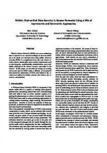
Figure 2. Acoustic Time-of-Flight Ranging. BS is the base station connected to a computer. The MICA2 motes are labeled a, b and c. Acoustic time-of-flight ranging is both an accepted and easily implemented ranging technique. This section details the strategy of time-of-flight ranging we implemented (see Figure 2 for a diagram). The first step is to send a message to a ranging endpoint node. The endpoint node, after receiving the message, simultaneously broadcasts a radio ranging message with a 4 kHz chirp. Every node in the network is configured to listen for the radio ranging messages and starts a timer which stops when the audible chirp is heard. A broadcast message announcing the distance between the endpoint and receiving nodes is then sent for all who are interested. Ranging is possible in this setup due to the differential in radio transmission speed (governed by the speed of light, the radio stack, and system-level issues) and the speed of sound in the sensing environment (we use 346.65 m/s for our experiments which corresponds to the speed of sound in air at 25 degrees Celsius). The granularity of the timer on the receiving nodes primarily dictates the uncertainty in the ranging estimates. We currently see average errors of 2.0m between pairs of motes. For the remainder of the paper, we assume that localization can be done more accurately with more advanced technology (e.g., average error of 3cm for 433MHz radio link as reported in [6]).
4
Stereo and Localization Data Fusion
Stereo and localization data fusion brings the results of the preceding sections together in a consistent manner. Specifically, it allows us to (a) calibrate a depth map given localization data collected from the same scene and (b) calibrate sensor locations given a depth map. Section 4.1 introduces the problem of stereo and localization data fusion. Section 4.2 details techniques that can solve the data fusion problem, the simplest of which we have implemented. Section 4.3 reflects on results of our fusion algorithm on varying qualities of data.
4.1 Problem Statement In this paper, we focus on the problem of calibrating the depth map (obtained through computational stereopsis) using the localization data (obtained from the wireless sensor network). A depth map is simply an image of a scene with pixel values given by the depth of each scene point from the camera (the minimum distance from the scene point to the camera plane). Theoretically, the depth map is correct up to a scaling factor, so the problem reduces to the problem of calculating the scaling factor α. We look at solving the [more general] problem of a scaling factor and an offset. The offset β can presumably handle some systematic errors that we have unknowingly introduced by our techniques. In summary, equation (1) defines the depth map calibration relation. calib z depth (1) map = αz depth map + β
4.2 Proposed Approach The primary challenge in the data fusion problem is the registration of the depth map image with the wireless sensor locations. We are looking for depth map image locations where a sensor lies. This could be viewed as a matching problem assuming that a sensor shape or its intensity profile is uniquely defined with respect to all other scene objects. We have considered two approaches to this registration problem. In the first approach, a user manually specifies the correspondences (as we have done above for the stereo rectification problem). This consists of manually identifying pixels in the depth map (or the corresponding left stereo image) of a known sensor ID. If the localization step is completed successfully, knowing the sensor ID is equivalent to knowing the depth coordinate of calib the sensor, z sensor = z depth map . In the second approach, one can place sensors on visible planar surfaces in a sufficiently dense fashion. By incorporating the spatial arrangement of sensors, we can automate parts of the calibration as described in the following procedure. The sensor locations in a depth map image coordinate system are manually selected, and the calibration program fits the sensor locations to a plane in
the 3-D “world” coordinate system. This plane is used for depth map calibration since in the “camera” coordinate system, the image points corresponding to the sensors will also form a plane. The depth map calibration is based on the fact that all sensor locations relative to an arbitrary point taken to be the “left” camera, in our setup, are known to be within scale, offset, and rotational factors (i.e. five degrees of freedom). In this work, we use the second approach for fusing stereo and wireless sensor locations. In general, one would desire to identify a large plane, both in terms of sensors falling on it, and in percentage of image covered. Techniques for finding a planar subset in a collection of 3D points exist in the literature, for instance in [22]. We avoided this problem by manually selecting points from the stereo pair that lie on a plane in a world coordinate system defined by the left camera. We continue by finding the parameters of the plane in 3-D that fits the sensor “world” coordinate locations using a linear least squares approach and minimizing the squared error in z (the axis perpendicular to the image plane). We fit the plane ax + by − z + d = 0 to the sensor real-world coordinate locations. Using the computed plane parameters (a, b, d) we then make the calib
substitution for z depth map using equation (1) and solve (in a linear least squares fashion) the resulting problem over all known points to obtain α and β. At this point the depth map can be calibrated and the results compared against what is known. It is important to use high-quality points for the calibration step. In addition to the requirement that the points be coplanar, a good fit is dependent on valid depth map data for the points. As mentioned in [23], stereopsis will fail for points which are occluded, near specularities, or in areas of insufficient texture. Points meeting some or all of these criteria should not be used for calibration and have been avoided in this section.
4.3 Experimental Results Section 4.2 covered the implementation of the fusion algorithm used in Image to Knowledge. Section 4.3.1 covers the details of our evaluation methodology for this algorithm. The quantitative results from our experiments are reported in section 4.3.2.
4.3.1
Methodology for Accuracy Evaluations
Ultimately, we measure our fusion performance by the accuracy of the resulting depth map relative to a ground truth depth map. In practice, the ground truth depth map is generally not available, or is very difficult to obtain. The situation is a bit different in our experimental setup as we have the ability to acquire ground truth measurements. We conducted experiments with theoretical/synthesized stereo pairs and actual/measured stereo pairs. In the
synthetic image case, we can generate a dense, theoretically correct depth map. In the real-world cases, we do not have the luxury of a dense depth map and must resort to a relatively small set of points at hand-verified distances. Another issue is the error metric for comparing ground truth depth maps with estimated depth maps. We consider two error metrics: (a) the average absolute distance error for each pixel/hand-verified point, and (b) the average relative distance error as a percentage of maximum measured range in the image. Both values decrease with more accurate calibration (fusion) and are asymptotically optimal (zero). The accuracy evaluation methodology for each set of input images is outlined next.
function of scene texture and calibration model complexity. Specifically, we conducted experiments that change the amount of texture in the scene (which affects the quality of the stereo output). We also include results which have been calibrated using only “scaled” depth We observed that the maps (assuming β = 0 ). calibration results under the assumption of β = 0 led to smaller error in some cases, seemingly due to the sensitivity of calibration to the quality of the plane fit.
Methodology: 1. Obtain a stereo pair 1a. Synthetic Images: Create a synthetic stereo pair using computer graphics program like POV-Ray. 1b. Real Images: Take a stereo pair of a real scene using a digital camera. 2. Prepare ground truth data 2a. Synthetic Images: Derive a theoretical depth map based on the geometry of the scene. Pick N points and compute their distance. Four of these points will be used for calibration and should lie in a plane. 2b. Real Images: Record manually distance measurements to N points (N>4) in the scene. Four of these points will be used for calibration and should lie in a plane. Measure the maximum range of the scene depth (used in step 6) 3. Compute an uncalibrated depth map z depth map
4.
from a stereo pair of images using the I2K Stereo tool. Select M points (M=4) from step 2 that fall in a plane, calibrate the depth map from step 3 using
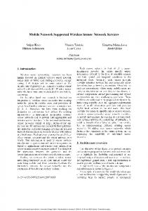
Figure 3: Synthetic Plane. Top – The input [rectified] stereo pair generated with POV-Ray, Bottom – Computed depth map (pseudo-color) As an algorithm test, we generated a synthetic stereo pair (Figure 3) consisting of a single textured plane. We fitted a plane to four image points, as before, and verified that the fitted plane had a normal consistent with the theoretical prediction regardless of the specific implementation of a stereo method. The scale and offset factors differed, however, leading to differing errors in the calibrated depth map. Our results (excluding a border of width 100 pixels) are summarized in Table 1.
calib
Offset β
Avg. Absolute Dist. Error
Maximum Image Range
Error % of Max Range
Table 1: Results obtained for a synthetic stereo pair consisting of a single textured plane.
Scale α
5.
equation (1). Compute the average absolute distance error using all points from step 2 (excluding a border of a given width due to different fields of view). 1 calib Avg. Abs. Dist. Error = zdepth map (i ) − zactual (i ) N i∈Points
Number of Points
the I2K Stereo tool to obtain z depth map based on
Scale Only
57408
0.705
N/A
0.049
12
0.41%
Scale and Offset
57408
0.745
-0.604
0.057
12
0.43%
∑
6.
Compute the average relative distance as a percentage of maximum measured range. The maximum distance of the points from step 2 is “Max Range” and we use: Error % of Max Range =
4.3.2
(Avg. Abs. Dist. Error) ⋅ 100% (Max Range)
Results
We performed a number of different experiments in order to quantitatively evaluate the accuracy of results as a
During testing with real stereo pairs, shown in Figure 4, the phenomenon of near-zero scaling factors occurred numerous times, creating very large calibration errors. We believe this phenomenon arises due to over-fitting of our calibration points. The errors in the chosen points allow for a local minimum “fit” that is just their average
of a calibrated stereo rig) since the depth map values can have arbitrary scale. We do not have data on how these range estimates compare with range estimates obtained using a calibrated stereo rig as we do not have currently access to such equipment. This comparison is left as an area for further research.
Untextured Real Scene
Textured Real Scene
Table 2: Calibration Evaluations. In cells with multiple numbers, the top number represents good scene points and the bottom number represents bad scene points. The good and bad points are defined according to Section 4.2 in the context of stereopsis. Textured Synthetic Scene
(i.e. purely an offset), rather than a purely scaled, or mixed solution that approaches the global minimum error. Theory predicts that scaling is the only operation needed to achieve the global minimum, so incorporating this a priori knowledge into the fitting step is the “correct” thing to do. In real and synthetic stereo pairs, this is not always true, possibly due to unknown systematic errors. Fortunately, both “scaling”, and “scaling and offsetting” result in empirically similar numbers, suggesting that either choice will work. We present both figures in our calibration results in Table 2. As discussed in Section 4.2, scene points can be good or bad in the context of stereopsis, the bad points being points where stereopsis fails (image match cannot be made). Bad scene points can obviously skew error results, but they are very real. Table 2 includes two sets of numbers for good and bad scene points respectively. This is to give the reader a sense of the extremes seen in practice.
Maximum Image Range Avg. Absolute Dist. Error ( α ≠ 0, β ≠ 0 )
10 6 13 units 1.538 3.042
9 6 7.7m 0.423m 3.792m
9 6 7.7m 0.396m 2.578m
Avg. Absolute Dist. Error (“scaled only” or β = 0 )
0.574 5.494
0.612m 5.447m
0.333m 3.030m
Error % of Max Range ( α ≠ 0, β ≠ 0 )
11.8% 23.3%
5.5% 49.2%
5.1% 33.4%
Error % of Max Range (“scaled only” or β = 0 )
4.4% 42.3%
7.9% 70.7%
4.3% 39.4%
Number of Points
Finally, we consider the magnitude of the error and relate it to the accuracy of the image matching using the textured, real scene from Figure 4 and Table 2 as an example. According to Eq. (1) and by assuming β to be zero, we found α to be 191.25. This produces the relation given in Eq. (2).
calib zdepth map = 191.25 z depth map = Figure 4: Stereo Pairs used for Evaluation. Top - The untextured, real scene. Middle - The textured, real scene. Bottom - The textured, synthetic scene. As expected according to our discussion in Section 2.2, we find that our algorithm performs best when texture is present. In an attempt to make a valid comparison between performance on synthetic and real data sets, we created a synthetic image with similar geometry to the actual scene and utilized the same number of calibration and testing points. In our controlled setup, we find the results from the synthetic and real scenes measured using error percent of max range to be comparable. The number of test points from the actual room is constrained by measurement time. We do not consider or compare our results with the error seen in the uncalibrated depth map (without the use
191.25 disparity
(2)
Consider a point at half the maximum image range (i.e. 3.85m from the camera corresponding to a disparity of 50 pixels). We see that a 0.333m error (4.3% of the maximum image range) corresponds to a disparity error of approximately 3 to 5 pixels (Round(191.25/3.85) – Round(191.25/(3.85±0.333)). If we carry out a similar calculation for the bad scene points with an average error of 3.030m, we find this corresponds to disparity errors of over 20 pixels. The input images have scanlines of 500 pixels, so these disparity errors correspond to 0.9% and greater than 4% of the scanline length respectively. We believe that these 3 to 5 pixel matching errors for good scene points are reasonable and should be expected since any image matching technique will have some error and
uncertainty. We refer the reader to [1] and [23] for discussions of more complex image matching techniques.
[3] D. Marr, Vision, San Francisco: W.H. Freeman, 1982.
5
[4] Network and Mobile Systems Group, CSAIL, MIT, “The Cricket Indoor Location System,” Aug. 2004; http://nms.lcs.mit.edu/projects/cricket/.
Conclusion
We presented the results of a preliminary study about depth estimation by fusing stereo vision and wireless sensor locations. Other approaches to calibrating wireless sensor locations, or calibrating depth maps and sensor localizations according to their range dependent uncertainty are explored in [24]. The depth map calibration using wireless sensor networks presented in this paper is one possible application how to utilize estimated spatial information. For this application to become feasible, more research needs to be done on the underlying problems, especially on algorithms that do not require human intervention. On the infrastructural level, accurate ranging in wireless sensor networks remains a problem. Some of this may be alleviated with future commercial developments (and related software), such as ultrasound sensor boards. On the algorithmic level, robust techniques for matching image points need to be explored. The critical issue of matching is demonstrated by the range of errors in Table 2. We plan to address the problem of robust image matching in the future by minimizing and identifying stereopsis failures and hence selecting only good points. This way, we will be able to produce the good fusion results as reported in Table 2. The good and bad points used in this paper were determined manually in order to understand typical worst-case and best-case errors. Once these problems have been solved, this application may become very useful as it does not require the use of precise cameras or calibrated stereo rigs. As wireless sensor networks and pervasive computing become a commercial reality, this capability can become the underlying layer of high-level recognition and response mechanisms: one piece of a “smarter” world.
6
Acknowledgement
This material is based upon work partially supported by the National Center for Advanced Secure Systems Research (NCASSR) of the Office of Naval Research (ONR). We would also like to acknowledge the support of Dr. Himanshu Khurana from NCSA UIUC.
References
[5] K. Whitehouse and X. Jiang, “Calamari: A Localization System for Sensor Networks,” Aug. 2004; http://www.cs.berkeley.edu/~kamin/calamari/. [6] AT&T Laboratories Cambridge, “The Bat Ultrasonic Location System,” Aug. 2004; http://www.uk.research.att.com/bat/. [7] N.B. Priyantha, H. Balakrishnan, E. Demaine, and S. Teller, “Anchor-Free Distributed Localization in Sensor Networks,” Tech Report 892, Laboratory for Computer Science, MIT, 2003. [8] S. Pankanti and A.K. Jain, “Integrating Vision Modules: Stereo, Shading, Grouping, and Line Labeling,” PAMI, Vol. 17, Num. 9, Sep. 1995, pp 831-842. [9] J. Hightower and G. Borriello, “Location Systems for Ubiquitous Computing,” IEEE Computer, Vol. 34, Num. 8, Aug. 2001, pp. 57-66. [10] H. Hogan, “Giving Machine Vision Much-Needed Depth Perception,” Photonics Spectra, May 2005, pp. 5862. [11] W. Roush, A.M. Goho, E. Scigliano, D. Talbot, M.M. Waldrop, G.T. Huang, P. Fairley, E. Jonietz, and H. Brody, “10 Emerging Technologies,” Technology Review, Vol. 106, No. 1, 2003, pp 33-46. [12] Crossbow Technologies, Inc., “MPR400 MICA2 Datasheet,” Aug. 2004; http://www.xbow.com/Products/Product_pdf_files/ Wireless_pdf/6020-0042-05_A_MICA2.pdf. [13] UC Berkeley, “TinyOS Community Forum,” Aug. 2004; http://www.tinyos.net/. [14] ALG, NCSA, UIUC, “I2K – Image to Knowledge,” Aug. 2004; http://alg.ncsa.uiuc.edu/do/tools/i2k/.
[1] H. Wechsler, Computational Vision, Boston: Academic Press, 1990.
[15] S. Roy, “Stereo Without Epipolar Lines: A Maximum-Flow Formulation,” International Journal of Computer Vision, Vol 34, No. 2/3, 1999, pp 147-161.
[2] P. Dario, M. Bergamasco, A. Bicchi, and A. Fiorillo, “Multiple Sensing for Dexterous End Effectors,” Robots with Redundancy: Design, Sensing and Control, A.K. Bajcsy, ed., Berlin: Springer Verlag, 1992.
[16] R. Sara, “Accurate Natural Surface Reconstruction from Polynocular Stereo” in Confluence of Computer Vision and Computer Graphics, Ed. A. Leonardis, et al, Boston: Kluwer Academic Publishers, 1999.
[17] U. Dhond and J.K. Aggarwal, "Structure from Stereo--A Review," IEEE Transactions of Systems, Man, and Cybernetics, Vol. 19, No. 6, Nov 1989, pp 1489-1510. [18] Z. Zhang, “A Flexible New Technique for Camera Calibration,” IEEE Transactions on Pattern Analysis and Machine Intelligence, Vol. 22, No. 11, pp 1330-1334. [19] R.I. Hartley, “Theory and Practice of Projective Rectification,” International Journal of Computer Vision, Vol. 35, No. 2, 1999, pp 115-127. [20] F. Isgro and E. Trucco, “Projective Rectification without Epipolar Geometry,” Computer Vision and Pattern Recognition (CVPR), Vol. 1, June 1999, pp 94-99. [21] H. Hirschnuller, “Improvements in Real-Time Correlation-Based Stereo Vision,” IEEE Workshop on Stereo and Multi-Baseline Vision, Kauai, Hawaii, Dec. 2001, pp 141-148. [21] D. Scharstein and R. Szeliski, “Middlebury Stereo Vision Page,” Aug. 2004; http://cat.middlebury.edu/stereo/. [22] K. Okada, S. Kagami, M. Inaba, and H. Inoue, “Plane Segment Finder: Algorithm, Implementation and Applications,” Proceedings IEEE International Conference on Robotics & Automation, Seoul, Korea, May. 2001, pp 2120 – 2125. [23] M.Z. Brown, D. Burschka, and G.D. Hager, “Advances in Computational Stereo,” PAMI, Vol. 25, Num. 8, Aug. 2003, pp 993-1008. [24] D.J. Scherba, “Fusion of Stereo Depth Maps and Sensor Localization in Wireless Sensor Networks,” MS Thesis, ECE UIUC, June 2005.