Stereo Image and Depth Map Generation for Images with Different Views and Resolutions Chiman Kwan Applied Research LLC Rockville, USA
[email protected]
Bryan Chou Applied Research LLC Rockville, USA
[email protected]
Abstract—There are many practical applications where stereo images and depth maps may need to be generated using cameras with different resolutions and view angles. One challenge is that the parallax in images may create issues in image alignment. Another challenge is on how to handle the different resolutions. This paper presents some preliminary results in enhancing the stereo images and depth maps using the uncalibrated images with different resolution and view angles. Our goal is to investigate whether or not we can combine the images with different resolutions and view angles to generate high quality stereo images and depth maps. We first enhance the low resolution image (assuming it is the left image without loss of generality) with help from the high resolution image (assuming it is the right image). We then combine the improved left image and the original high resolution right image to create high quality stereo and depth maps. Actual images from the Middlebury database were used in our experiments. Preliminary results demonstrated that the proposed approach works to certain extent. There is still room for performance improvement. Keywords—Image enhancement, image alignment, stereo image, depth map, pansharpening, Mastcam.
I. INTRODUCTION In many practical applications [1][2], it is necessary to align images with different views. The parallax due to different views causes serious problems in image alignment, as most registration algorithms are applicable to only images with planar contents. Fig. 1 shows one example about registration issues for images having contents at different depths. It can be seen that feature correspondence can only be achieved either in the foreground or background, but not both. Moreover, some applications may have different resolutions in the left and right cameras. For example, the Curiosity rover has a few instruments [3]-[5] for studying the Mars surface. There are two Mastcam multispectral imagers in Mars Science Laboratory (MSL) onboard the rover [5]. The left imager has wide field of view, but has 3 times lower resolution than that of the right. For stereo image formation using the Mastcam images, the existing practice is to make the right images to have the same resolution as the left by downsampling the right images. This will avoid artifacts caused by the demosaicing process in the Bayer pattern and also by the lossy JPEG compression process. Although such a practice is useful, it may limit the full potential of Mastcams. In particular, existing stereo images do not have high resolution, which may degrade the augmented reality or virtual reality experience of science fans. This research was supported by NASA JPL under contract # 80NSSC17C0035. 978-1-5386-7693-6/18/$31.00 ©2018 IEEE
Bulent Ayhan Applied Research LLC Rockville, USA
[email protected]
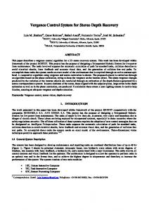
(a) Matched feature points from the background
(b) Matched feature points from the foreground Fig. 1: Registration issues for images having non-planar contents. Feature points can only match either in the foreground or in the background.
In the past two decades, advances have been made in image super-resolution. Pansharpening is one popular super-resolution technique [6]-[16]. In pansharpening, a low-spatial resolution multispectral data cube is fused with a high-spatial resolution panchromatic image (PAN) [7]. Recently [17]-[19], we have applied some pansharpening algorithms to enhance the Mastcam images and achieved good performance. In this research, we investigated how we can generate stereo images and depth maps for uncalibrated cameras with different resolutions and view angles. The goal is to generate high resolution stereo images and depth maps using images with both low and high resolutions. Given two images with different resolutions and view angles, we first improve the resolution of the left image with help from the right image. The image pair with a common field of view is aligned using a two-step image registration algorithm. Sub-pixel registration accuracy can be achieved. In the event that the image contents are not coplanar, we propose to use the original left image and the right image to get a depth map. We then divide the depth map into multiple layers and perform registration for each layer separately. The alignment results from different layers are then merged. We then use the enhanced left image and the original right image to generate a stereo image and a disparity map. This step comprises several sub-steps, including feature extraction, feature correspondence, image rectification, stereo image formation, and depth map generation. The proposed scheme has been
implemented and applied to Middlebury stereo image database. Initial results are quite encouraging. This paper is organized as follows. Section II briefly describes those key algorithms used in this study. Section III summarizes the data used and all the experimental results. Finally, we conclude the paper and point out some research directions in Section IV. II. KEY ALGORITHMS Low resolution Left image upsampling
Pansharpening High resolution left image
Fig. 2 below shows the signal flow. In the subsequent sections, we will summarize the key algorithms. Low resolution Left image
High resolution Right image Two-step Image Alignment Aligned right image Create Pan band
extraction, feature points matching between left and right images, estimation of fundamental matrix, outliers removal based on epipolar constraint, and image rectification, can be used. Fourth, based on the stereo image, a disparity map can then be generated.
upsampling
High resolution Right image Depth Map generation Divide Depth Map into multiple levels
High resolution Right image
Stereo image formation
Disparity map generation
Depth map generation
Fig. 2: Signal flow of a new stereo image formation and depth map generation system.
Here, we propose a new approach to high resolution stereo image formation and high resolution disparity map generation. As shown in Fig. 2, the approach consists of the following steps. First, an accurate two-step image registration approach is used to align the left and right images. We use the left image as the reference for registration. The coarse step is to use scale invariant features transform (SIFT) or speeded up robust features (SURF) features with RANSAC (Random Sample Consensus). The fine step is to apply a diffeomorphic algorithm to achieve subpixel accuracy. The common area between the left and right images is then extracted. The alignment can achieve sub-pixel accuracy. In the event that the image contents are not coplanar, we propose a scheme shown in Fig. 3 to use the original left image and the right image to get a disparity map. We then divide the disparity map into many layers and perform registration for each layer separately. The alignment results from different layers are then merged. Second, a panchromatic (pan) band is created using the multispectral bands in the right image. One simple way to create the pan band is to take the average of all the available bands in the right camera. Any pansharpening algorithms can be used for pansharpening. In the examples in this paper, a pansharpening algorithm known as Gram-Schmidt Adaptive (GSA) algorithm was used to pansharpen the left image. Third, the pansharpened left image and the original high resolution right image are then used to create a stereo image. In the stereo image creation process, some standard procedures, including feature points
Two-step Image Alignment
Fig. 3: Alignment scheme to deal with non-coplanar image contents.
A. Image Registration We applied a two-step image alignment approach [17] as shown in Fig. 4. RANSAC (Random Sample Consensus) technique [20] is used for an initial image alignment. Here, we use the two RGB images from the left and right images for getting the registration parameters. First, SURF features [21] and SIFT features [22] are extracted from the two images. Second, these features are then matched within the image pair. RANSAC is then applied to estimate the geometric transformation. The second step of the two-step process uses this aligned image with RANSAC and the left camera image as inputs and applies the Diffeomorphic Registration [24] technique. This second step reduces the registration errors to subpixel levels so that pansharpening can be performed.
Fig. 4. Block diagram of the two-step image alignment approach [17].
B. Pansharpening The goal of pansharpening is to fuse a low-spatial resolution left image with a high-spatial resolution panchromatic image (pan) from the right camera. In our case, after the two-step
registration, the image from the left camera can be considered as a blurred version of the right one. Therefore, we propose to apply pansharpening to sharpen the images from the left camera using high resolution images from the right camera as the panchromatic reference image. In this paper, we used the component substitution approach, which is simple and computationally efficient. In particular, we applied the Gram-Schmidt Adaptive (GSA) [7] algorithm for its simplicity and performance in our experiments. C. Stereo Image and Depth Map Generation Fig. 5 shows the key steps in stereo image formation. Given a pansharpened left image and the original high resolution right image, we first perform feature points extraction. This step is similar to the two-step image registration described earlier. Both SIFT and SURF features can be used. In the past, we found that SIFT features are more robust than SURF features. Second, the feature correspondence can be achieved with RANSAC, which matches feature points that belong to the same physical locations. Third, the fundamental matrix is estimated based on the corresponded feature points. Fourth, outliers are removed using the epipolar constraint. Finally, an image rectification step is performed.
(a) Two general image plane
(b) Rectified image planes
(c) Stereo image pair with proper baseline Fig. 6: Image rectification process [23].
Disparity is the difference between two pixels that correspond to the same physical point in the stereo image pair. Once the stereo images are created, a feature correspondence process is needed to determine the pixels that belong to the same physical point. Based the feature correspondence results, the disparity map is computed for every pixel in the image. Fig. 7 illustrates the relationship between depth and disparity. Once disparity map is found, we can use the following formula to compute the depth, L, for each pixel.
L = Bf / ΔX where B is the baseline between the two cameras, f is the focal length, and ΔX is the disparity at a particular pixel.
Fig. 5: Procedures in stereo image formation.
To illustrate the stereo rectification process, we use Fig. 6 below. “Camera 1” and “Camera 2” as shown in Fig. 6 (a), we aim at obtaining a stereo pair from these two images through image rectification, which consists of two steps. First, a homography is found for each image and we transform these two images to the new ones, which are identical to the ones captured by two parallel cameras (Fig. 6 (b)). Second, we adjust the baseline of the two parallel cameras to a proper value by translating the new images with a suitable value. The final stereo pair is formed (Fig. 6(c)).
Fig. 7: Relationship between disparity and depth.
III. EXPERIMENTAL STUDIES A. Middlebury Data The Middlebury stereo data set collected in 2014 contains 33 stereo images [25]. Each stereo image has ground truth depth maps as well as the raw left and right images. Calibration
parameters are also available. The left and right images have the same resolution. In our studies in Section III.B, we deliberately reduce the resolution of the left images by four times. B. Experimental Results In this section, we include three case studies. Case 1: Motorcycle. Fig. 8 shows the original low resolution left and the pansharpened right images. Fig. 9 shows the zoomed view of those images in Fig. 8. It can be seen that the image quality has been improved. Fig. 10 shows the comparison between the ground truth stereo image and the one generated by using the pansharpened left and HR right images. Fig. 11 shows the comparison of depth maps. It can be seen that the quality of the depth map has been improved using the enhanced left image.
(a) Stereo image (Red-cyan anaglyph) ground truth;
(b) Stereo image (Red-cyan anaglyph) formed using enhanced left and high resolution right. Fig. 10: Comparison of stereo image (ground truth) and the one generated by using the enhanced left image and high resolution right image. 250
(a) Before pansharpening; 200
150
100
50
0
(a) Depth map using low resolution left and high resolution right; (b) After pansharpening Fig. 8: Left image (Motorcycle) before and after pansharpening.
250
200
150
100
50
Fig. 9: Zoomed view of Fig. 8. Left image (Motorcycle) before and after pansharpening.
0
(b) Depth map using enhanced left and high resolution right;
250
200
150
100
50
0
(c) Ground truth depth map Fig. 11: Comparison of depth maps generated by using low resolution/enhanced left images and high resolution right image.
(a) Stereo (red-cyan anaglyph) ground truth;
Case 2: Shelves Fig. 12 shows the left image before and after pansharpening. Fig. 13 shows the zoomed view of Fig. 12. It can be easily seen that the image quality is better after pansharpening. Fig. 14 compares the stereo images formed using original left and enhanced left images. Although it is hard to see the improvement visually, the quality is slightly better. Similarly, the disparity maps in Fig. 15 show that the one using enhanced left image has smooth transition between the different depths. (b) Stereo image (red-cyan anaglyph) formed using enhanced left and high resolution right. Fig. 14: Comparison of stereo images generated by using low resolution/enhanced left images and high resolution right image. 250
200
150
100
(a) Before pansharpening; 50
0
(a) Depth map using low resolution left and high resolution right; 250
200
150
(b) After pansharpening Fig. 12: Left image (Shelves) before and after enhancing.
100
50
0
(b) Depth map using enhanced left and high resolution right; Fig. 13: Zoomed view of Fig. 12. Left image (Shelves) before and after enhancing.
250
200
150
100
50
0
(c) Ground truth depth map. Fig. 15: Comparison of disparity maps generated by using low resolution/enhanced left images and high resolution right image.
(a) Stereo (red-cyan anaglyph) ground truth;
Case 3: Chair Fig. 16 shows the left and pansharpened left image of a third case. Fig. 17 shows the zoomed version of Fig. 16. The improvement is obvious. Similar to earlier cases, the stereo image and disparity map in Fig. 18 and Fig. 19 all show improvement over the non-sharpened case.
(b) Stereo image (red-cyan anaglyph) formed using enhanced left and high resolution right. Fig. 18: Comparison of stereo images generated by using low resolution/enhanced left images and high resolution right image. 250
200
150
(a) Before pansharpening; 100
50
0
(a) Depth map using low resolution left and high resolution right; 250
200
150
(b) After pansharpening Fig. 16: Left image (Chair) before and after enhancing. 100
50
Fig. 17: Zoomed view of Fig. 16. Left image (Chair) before and after enhancing.
0
(b) Depth map using enhanced left and high resolution right;
250
200
150
100
50
(c) Ground truth depth map. Fig. 19: Comparison of disparity maps generated by using low resolution/enhanced left images and high resolution right image.
IV. CONCLUSIONS We present a new approach to generating high resolution stereo image and depth map for images with different resolutions and view angles. Initial results are very encouraging. One future direction is to further improve the registration performance for different depths. Other potential applications include the possibility of using the stereo maps for anomaly detection [26]-[30] or target tracking [31][32]. REFERENCES [1] B. Han, et al., “Depth-based image registration,” Proc. SPIE 7699, Algorithms for Synthetic Aperture Radar Imagery XVII, 76990Y, 18 April 2010. [2] C. Kwan, B. Chou, and B. Ayhan, “Enhancing Stereo Image Formation and Disparity Map Estimation for Mastcam Images,” IEEE Ubiquitous Computing, Electronics & Mobile Communication Conference, 2018. [3] W. Wang, S. Li, H. Qi, B. Ayhan, C. Kwan, and S. Vance, “Revisiting the Preprocessing Procedures for Elemental Concentration Estimation based on CHEMCAM LIBS on MARS Rover,” 6th Workshop on Hyperspectral Image and Signal Processing: Evolution in Remote Sensing, 2014. [4] B. Ayhan, C. Kwan, and S. Vance, “On the Use of a Linear Spectral Unmixing Technique for Concentration Estimation of APXS Spectrum,” J. Multidisciplinary Engineering Science and Technology, Volume 2, Issue 9, pp. 2469-2474, September, 2015. [5] J. F. Bell et al., “The Mars Science Laboratory Curiosity Rover Mast Camera (Mastcam) Instruments: Pre-Flight and In-Flight Calibration, Validation, and Data Archiving,” AGU J. Earth and Space Science, 2017. [6] J. Zhou, C. Kwan, and B. Budavari, “Hyperspectral Image SuperResolution: A Hybrid Color Mapping Approach,” SPIE Journal of Applied Remote Sensing, Vol. 10, article 035024, September, 2016. [7] G. Vivone, L. Alparone, J. Chanussot, M. Dalla Mura, Garzelli, and G. Licciardi, “A critical comparison of pansharpening algorithms,” IEEE Int. Conf. Geoscience and Remote Sensing (IGARSS), July 2014. [8] C. Kwan, J. H. Choi, S. Chan, J. Zhou, and B. Budavari, “Resolution Enhancement for Hyperspectral Images: A Super-Resolution and Fusion Approach,” IEEE International Conference on Acoustics, Speech, and Signal Processing, New Orleans, 2017. [9] C. Kwan, B. Budavari, A. Bovik, and G. Marchisio, “Blind Quality Assessment of Fused WorldView-3 Images by Using the Combinations of Pansharpening and Hypersharpening Paradigms,” IEEE Geoscience and Remote Sensing Letters, August, 2017. [10] C. Kwan, B. Budavari, and F. Gao, “A Hybrid Color Mapping Approach to Fusing MODIS and Landsat Images for Forward Prediction,” Remote Sensing, March 2018. [11] C. Kwan, J. H. Choi, S. Chan, J. Zhou, and B. Budavari, “A SuperResolution and Fusion Approach to Enhancing Hyperspectral Images,” Remote Sensing, September 2018. [12] C. Kwan, B. Ayhan, and B. Budavari, “Fusion of THEMIS and TES for Accurate Mars Surface Characterization,” IEEE International Geoscience and Remote Sensing Symposium (IGARSS), Fort Worth, July 2017.
[13] C. Kwan, C. Haberle, A. Echavarren, B. Ayhan, B. Chou, B. Budavari, and S. Dickenshied, “Mars Surface Mineral Abundance Estimation Using THEMIS and TES Images,” IEEE Ubiquitous Computing, Electronics & Mobile Communication Conference, New York City, November 2018. [14] Y. Qu, H. Qi, B. Ayhan, C. Kwan, and R. Kidd, “Does Multispectral/Hyperspectral Pansharpening Improve the Performance of Anomaly Detection?” IEEE International Geoscience and Remote Sensing Symposium (IGARSS), Fort Worth, July 2017. [15] M. Dao, C. Kwan, K. Koperski, and G. Marchisio, “A Joint Sparsity Approach to Tunnel Activity Monitoring Using High Resolution Satellite Images,” IEEE Ubiquitous Computing, Electronics & Mobile Communication Conference, 2017. [16] C. Kwan, B. Budavari, M. Dao, and J. Zhou, “New Sparsity Based Pansharpening Algorithm for Hyperspectral Images,” IEEE Ubiquitous Computing, Electronics & Mobile Communication Conference, 2017. [17] B. Ayhan, M. Dao, C. Kwan, H. Chen, J. F. Bell III, and R. Kidd, “A Novel Utilization of Image Registration Techniques to Process Mastcam Images in Mars Rover with Applications to Image Fusion, Pixel Clustering, and Anomaly Detection,” IEEE Journal of Selected Topics in Applied Earth Observations and Remote Sensing, August, 2017. [18] M. Dao, C. Kwan, B. Ayhan, and J. F. Bell, “Enhancing Mastcam Images for Mars Rover Mission,” 14th International Symposium on Neural Networks, pp. 197-206, Hokkaido, Japan, June 2017. [19] C. Kwan, B. Budavari, M. Dao, B. Ayhan, and J. F. Bell, “Pansharpening of Mastcam images,” IEEE International Geoscience and Remote Sensing Symposium (IGARSS), Fort Worth, July 2017. [20] R. Hartley and A. Zisserman, Multiple View Geometry in Computer Vision, Cambridge University Press, 2003. [21] H. Bay, et al., “SURF: Speeded Up Robust Features,” Computer Vision and Image Understanding (CVIU), Vol. 110, No. 3, pp. 346–359, 2008. [22] D. G. Lowe, “Object recognition from local scale-invariant features.” IEEE International Conference on Computer Vision, vol. 2, 1999. [23] X. Li, C. Kwan, and B. Li, “Stereo Imaging with Uncalibrated Camera,” Advances in Visual Computing, Second International Symposium, 2006. [24] H. Chen, et al., “A Parameterization of Deformation Fields for Diffeomorphic Image Registration and Its Application to Myocardial Delineation,” Lecture Notes in Computer Science Volume 6361, 2010. [25] D. Scharstein, et al., “High-resolution stereo datasets with subpixelaccurate ground truth,” German Conf. on Pattern Recognition, 2014. [26] J. Zhou, C. Kwan, B. Ayhan, and M. Eismann, “A Novel Cluster Kernel RX Algorithm for Anomaly and Change Detection Using Hyperspectral Images,” IEEE Trans. Geoscience and Remote Sensing, Volume: 54, Issue: 11, pp. 6497-6504, Nov. 2016. [27] W. Wang, S. Li, H. Qi, B. Ayhan, C. Kwan, and S. Vance, “Identify Anomaly Component by Sparsity and Low Rank,” IEEE Workshop on Hyperspectral Image and Signal Processing: Evolution in Remote Sensor (WHISPERS), Tokyo, Japan, June 2-5, 2015. [28] Y. Qu, W. Wang, R. Guo, B. Ayhan, C. Kwan, and S. Vance, and H. Qi, “Hyperspectral Anomaly Detection through Spectral Unmixing and Dictionary based Low Rank Decomposition,” IEEE Trans. Geoscience and Remote Sensing, March 22, 2018. [29] Y. Qu, H. Qi, and C. Kwan, “Unsupervised Sparse Dirichlet-Net for Hyperspectral Image Super-Resolution,” Conference on Computer Vision and Pattern Recognition, Salt Lake City, June 2018. [30] S. Li, W. Wang, H. Qi, B. Ayhan, C. Kwan, and S. Vance, “Low-rank Tensor Decomposition based Anomaly Detection for Hyperspectral Imagery,” IEEE International Conference on Image Processing (ICIP), Quebec City, Canada, September 27-30, 2015. [31] X. Li, C. Kwan, G. Mei, and B. Li, “A Generic Approach to Object Matching and Tracking,” Proc. Third International Conference Image Analysis and Recognition, Lecture Notes in Computer Science, Volume 4141, pp 839-849, 2006. [32] C. Kwan, B. Chou, A. Echavarren, B. Budavari, J. Li, and T. Tran, “Compressive Vehicle Tracking Using Deep Learning,” IEEE Ubiquitous Computing, Electronics & Mobile Communication Conference, New York City, November 2018.