Deriving Software Architectures from Problem Descriptions Denis Hatebur and Maritta Heisel Universit¨at Duisburg-Essen
[email protected],
[email protected] Abstract: We show how software architectures (including interface descriptions) can be derived from artifacts set up in the analysis phase of the software lifecycle. The analysis phase consists of six steps, where various models are constructed. Especially, the software development problem is decomposed into simple subproblems. The models set up in the analysis phase form the basis for (i) defining software architectures related to single subproblems, (ii) merging the subproblem architectures to obtain the overall software architecture, and (iii) to define the interfaces between the components of the overall architecture. The approach is based on problem patterns (problem frames) and the architectural style of layered software architectures.
1
Introduction
Software development problems occurring in practice are mostly complex in nature. Their solution requires a thorough requirements analysis and a careful design. Requirements analysis and the development of an appropriate software architecture are closely related and should be conducted in a systematic way. In this paper, we present a method to derive software architectures from artifacts that are set up during the requirements analysis phase of the software lifecycle. That method makes use of patterns for requirements analysis as well as for developing software architectures. Requirements patterns are related to architectural patterns. Furthermore, the decomposition of complex problems into simpler subproblems plays an important role. Finally, information about the environment in which the software will operate is taken into account. In the following, we describe a model-driven process for requirements analysis that is based on problem frames [Jac01] in Sect. 2. This process produces a number of artifacts that can be used to systematically derive a software architecture. Section 3 describes this derivation. Section 4 describes related work. Section 5 summarizes the contributions of this paper.
2
Requirements Engineering Using Problem Frames
Our method for deriving software architectures works in connection with a pattern-based approach to requirements analysis. It makes use of patterns capturing different classes of software development problems, called problem frames [Jac01].
2.1
Problem Frames
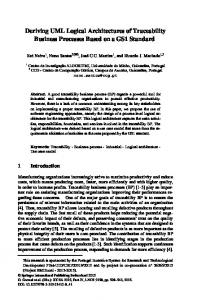
Problem frames are a means to describe software development problems. They were invented by Jackson [Jac01], who describes them as follows: “A problem frame is a kind of pattern. It defines an intuitively identifiable problem class in terms of its context and the characteristics of its domains, interfaces and requirement.” Problem frames are described by frame diagrams, which consist of rectangles, a dashed oval, and links between these (see frame diagram in Fig. 1). All elements of a problem frame diagram act as placeholders which must be instantiated by concrete problems. Doing so, one obtains a problem description that belongs to a specific problem class. ET!E1 WP!Y2
Y4
Workpieces X
Editing tool
Command effects US!E3
User
E3 B
E3:
user commands
E1:
editing operations
Y2:
workpieces status
Y4:
workpieces properties
Figure 1: Simple workpieces problem frame
Plain rectangles denote problem domains (that already exist in the application environment), a rectangle with a double vertical stripe denotes the machine (i.e., the software) that shall be developed, and requirements are denoted with a dashed oval. The connecting lines between domains represent interfaces that consist of shared phenomena. Shared phenomena may be events, operation calls, messages, and the like. They are observable by at least two domains, but controlled by only one domain, as indicated by an exclamation mark. For example, in Fig. 1 the notation US!E3 means that the phenomena in the set E3 are controlled by the domain User. A dashed line represents a requirements reference. It means that the domain is mentioned in the requirements description. An arrow at the end of such a dashed line indicates that the requirements constrain the problem domain. In Fig. 1, the Workpieces domain is constrained, because the Editing tool has the role to change it on behalf of user commands for achieving the required Command effects. Each domain in a frame diagram has certain characteristics. In Fig. 1 the X indicates that the corresponding domain is a lexical domain, and B indicates that a domain is biddable [Jac01]. Problem frames greatly support developers in analyzing problems to be solved. They show what domains have to be considered, and what knowledge must be described and reasoned about when analyzing the problem in depth. Other problem frames besides simple workpieces frame are required behaviour, commanded behaviour, information display, and transformation.
After having analyzed the problem, the task of the developer is to construct a machine based on the problem described via the problem frame that improves the behavior of the environment it is integrated in, according to its respective requirements. 2.2
Requirements Analysis Method
We use problem frames in a model-driven requirements analysis process. We call that process model-driven (in contrast to model-based), because the different models are related to one another. Thus, developing one model “drives” the development of the models to be set up in subsequent development steps. The process consists of the following six steps. To illustrate the different steps, we use a vacation rentals application, where users can book vacation homes via the Internet. A1 Problem elicitation and description The environment in which the software will operate is described by a context diagram. The notation of context diagrams is similar to the notation of frame diagrams, but here, the domains refer to concrete domains in the environment instead of variables, and context diagrams do not show the requirements1 . An example of a context diagram is shown in Fig. 2. “C” indicates a causal domain. Requirements are expressed in natural language, for example “A guest can book available holiday offers, which then are reserved until payment is completed.” In this phase, also domain knowledge is stated, which consists of facts and assumptions. An example of a fact is that each vacation home can be used by only one (group of) guests at the same time. An example of an assumption is that each guest either pays the full amount due or not at all (i.e., partial payments are not considered). Vacation V!{Status} Home C
Staff Member B S!{makeHolidayOffer, recordPayment, browseBookings, rate}
B!{Payments}
Holiday Offer
VR!{showBookings} Vacation Rentals
Bank C
VR!{Invoice, results}
G!{payInvoice}
X H!{availableHolidayOffer, Bookings reservedHolidayOffer, paidHolidayOffer} VR!{makingHolidayOffer, rated, setAvailableHolidayOffer recordingPayment, bookingHolidayOffer}
G!{browseHolidayOffers, bookHolidayOffer} Guest
G!{arrive, leave}
B
Figure 2: Context diagram for vacation rentals
A2 Problem decomposition For decomposing the problem into subproblems, related sets of requirements are identified. The subproblems should fit to problem frames, i.e., they should belong to known classes of software development problems. Fitting a problem to a problem frame is achieved by instantiating the respective frame diagram. An instantiated frame diagram is called a problem diagram. An instance of the simple workpieces frame (see Fig. 1) is shown in Fig. 1 In [Jac01] context diagrams also do not show the domain types and which domains are in control of shared phenomena.
3. The Editing tool to be implemented is called VR pay, the Workpieces domain is instantiated with the domain Holiday Offers, and the domain User is instantiated with the domain Staff Member. The requirement (R06) is “A staff member can record when a payment is received.” To make the problem diagram more comprehensible, we also show the relation to the Bank domain, which is not strictly necessary to solve the software development problem. Holiday Offers
H!{reservedHolidayOffer} VR!{recordingPayment} VR_ pay
paidHolidayOffer X (R06)
Payments
recordPayment Staff Member
S!{recordPayment}
Bank B!{Payments}
C
B
Figure 3: Instantiated simple workpieces problem frame
A3 Abstract software specification Whereas requirements refer to problem domains, specifications describe the machine (i.e., the software to be built). Domain knowledge is used to transform requirements into specifications. For more details, see [JZ95]. In our requirements analysis process, specifications are expressed as UML 2.0 sequence diagrams. These diagrams describe the interaction of the machine with its environment. Messages from the environment to the machine correspond to operations that must be implemented. These operations will be specified in detail in Step A5. Figure 4 shows the abstract specification corresponding to the subproblem shown in Fig. 3. There is one operation recordPayment to be specified further. Note that often operations have a return value and that the specifications corresponding to a subproblem may contain more than one operation. However, abstract specifications do not contain any technical details like GUI interactions. sd Pay
Staf f Member
Vacation Rentals
Holiday Of f er
{HOreserved AND ¬HOpaid} recordPayment recordingPayment
{HOreserved AND HOpaid}
Figure 4: Abstract specification for Pay subproblem
A4 Technical software specification In this step, the technical infrastructure in which the machine will be embedded is specified. For example, a web application may use the Apache web server. The result is a
technical context diagram, which refines the context diagram of Step A1 by specifying the technical means used by the machine for communicating with its environment. The technical context diagram for the vacation rentals example is given in Fig. 5. Mail Server VR C
SMTP
Mail Server Guest
POP3
SMTP HTTP Holiday Offer
X SQL Cmds
Vacation Apache API Rentals
Apache
Mail Client
C
HTTP C
M_UI
Guest
C G Web Browser
t Web SM Browser
B
Guest_UI C SM_UI C
Staff Member B
Figure 5: Technical context diagram
In the technical context diagram, the problem-related phenomena like recordPayment are mapped to technical phenomena like HTTP statements that are usually described by reference to an API description or a standard. A5 Operations and data specification In this step, the operations identified in Step A3 are specified in detail, using pre- and postconditions. The specification format is taken from the Fusion method [CAB+ 94]. Furthermore, the internal data structures to be used by the machine are specified now. Messages from the machine to its environment are specified using a sends clause. This information will be used for specifying interfaces of the software architecture to be defined in the design phase (see Sect. 3). A6 Software life-cycle In the final analysis phase, the overall behavior of the machine is specified. The name “life-cycle model” is again taken from the Fusion method [CAB+ 94]. In particular, the relation between the sequence diagrams associated to the different subproblems is expressed explicitly. Sequence diagrams can be related sequentially, by alternative, or in parallel.
3
Deriving a Software Architecture
Conducting requirements analysis according to the process described in Sect. 2.2 brings considerable advantages for developing the software architecture that expresses the coarsegrained structure of the machine: (i) Using problem frame makes it possible to obtain a candidate architecture for each subproblem by instantiating an architectural pattern. (ii) These subproblem architectures can be combined by applying a set of straightforward rules. (iii) A large part of the interface descriptions can be derived from the artifacts set up in the analysis phase. 3.1
Architectural Patterns for Problem Frames
For each problem frame, we have defined an architectural pattern for a software architecture that is suitable to solve the kind problem described by the respective problem frame [CHH05]. These patterns describe what components are necessary and how they are connected. They follow the layered architectural style. Of course, also other kinds
architectures may be used to solve the problems obtained in the analysis phase; however, the proposed architectural patterns provide an easy way to obtain a workable solution. The architectural pattern for the simple workpieces frame is shown in Fig. 6, together with its corresponding instance for the Pay subproblem. The application component is responsible to implement the overall functionality. All of our architectural patterns contain an application component. The user interface component consists of an adapter for a physical input device and an adapter for a (physical) display. The data storage component may for example be a database or a file. An adapter may be necessary for example to map editing operations (see Fig. 1) to SQL commands. Editing Tool
VR_pay Application
E3_if User Interface
VR_Application E1_Y2_if
Storage Adapter E1_Y2_if’’
SCmds Staff Member Interface
Storage
IHolidayOffer HO Adapter SQL cmds Holiday Offer
Apache API
E3_if’’ User (E3)
Staff Member (E3) Workpieces (E1, Y2)
Workpieces (E1, Y2)
Figure 6: Architectural pattern for simple workpieces problem frame and instantiation for Pay subproblem
3.2
Merging Subproblem Architectures
If the subproblems set up in Phase A2 of our requirements analysis process fit to problem frames, then a suitable software architecture for a subproblem can be obtained by simple instantiation of the corresponding architectural pattern. From these subproblem architectures, the architecture of the overall machine must be derived by an appropriate merge. The crucial point of this step is to decide if two components contained in different subproblem architectures should occur only once in the global architecture, i.e., if they should be merged. To decide this question, we make use of the information expressed in Step A6. Adapters and storage components belonging to the same physical device or data storage are merged. User interfaces are merged if they belong to the same user role. Application components belonging to sequential or alternative subproblems should be merged. Application components belonging to parallel subproblems should be merged if they share output phenomena; they should be kept separately, if the share neither input nor output phenomena; if they share input phenomena but no output phenomena, they can either be merged, or the input can be duplicated and the application components remain separate. These rules are described in more detail in [CHH06]. The overall software architecture for the vacation rentals problem is shown in Fig. 7.
VacationRentals VacationRentalsApplication
GCmds IHolidayOffer
SCmds
DB Adapter
SQLCmds
Guest Interface [0..*]
Check
Invoice
eMail Adapter
Staff Member Interface [0..*]
Timer
ModulAPI
Holiday Offer SMTP Client
(Driver + DBMS)
ApacheAPI
ApacheAPI Apache
Staff Member / Guest
SMTP eMail Server Guest
Figure 7: Overall software architecture for vacation rentals
3.3
Defining Interfaces of the Software Architecture
Using the techniques described in Sections 3.1 and 3.2, we obtain the structure of the machine to be built in terms of the necessary components. However, these components must be connected via interfaces, and these interfaces must also be described. For this purpose, we make use of the artifacts set up during the analysis process. Figure 8 shows the sources of information that can be used to define the respective interfaces. is_sent clauses from operation model (optional)
operations from operation model, is_sent clauses may be as return values
skeleton from problem diagrams and messages in sequence diagrams
Machine Application
User Interface
API of reused HAL component User
Adapter
DB Adapter
HAL component
Data Base
Timer
Hardware
internal operations from operation model machine interfaces from technical context diagram
Figure 8: Merged software architecture with interface information
The low-level interfaces (belonging to the lowest, i.e., most technical, layer of the architecture) can be obtained from the technical context diagram set up in Phase A4. The connection to hardware is achieved using a driver that is mostly delivered with the hardware itself. This driver is called hardware abstraction layer (HAL). Drivers are often re-used components, and therefore their interfaces provided to the adapters are usually given.
The interfaces of the application component should mostly correspond to high-level phenomena, as they are used in the context diagram (Phase A1) and the abstract specifications (Phase A3). The communication between users and the machine is usually bi-directional. The provided interface of the application domain connected to the user interface contains the operations identified in Phase A3 and specified in detail in Phase A5. The messages sent from the machine to its environment (defined by sends-clauses in Phase A5) may either correspond to return values of operations or to messages / operations contained in a required interface of the application that is connected to a provided interface of the user interface component. If the machine sends signals to some hardware, then these signals are contained in a required interface of the application component, connected to an adapter component. If the machine receives signals from some hardware, then these signals are contained in a provided interface of the application component, connected to an adapter component. (This case is not shown in Fig. 8). In both cases, the interfaces of the application component with hardware adapters contain phenomena that are specified in the context diagram of Phase A1. Storage or database components correspond to lexical domains. Therefore, such components are passive and thus only have provided interfaces, as shown in Fig. 8. The operations contained in these interfaces include the phenomena contained in the context diagram and the messages sent from the machine to the respective lexical domain as specified in the sequence diagrams of Phase A3. Since the phenomena in the context diagram contain no parameters, some refinement may be necessary. It may be required that the machine initiates some actions, for example sending out account statements to customers each month. Such an action corresponds to an internal operation, because it is not triggered from the environment. To implement internal operations, a timer component is necessary. The description of the internal operation as specified in Step A5 provides the information that is necessary to set up the interface between the timer and the application. As is visible in Fig. 8, the artifacts set up in the analysis phase provide enough information to define the interfaces of the software architecture almost completely.
4
Related Work
Since our approach heavily relies on the usage of patterns, our work is related to research on problem frames and architectural styles. However, we are not aware of similar methods that provide such a detailed guidance for developing software architectures as the method described in this paper. Aiming to integrate problem frames in a formal development process, Choppy and Reggio [CR00] show how a formal specification skeleton may be associated with some problem frames. Choppy and Heisel show that this idea is independent of concrete specification languages [CH03, CH04]. They also give heuristics for the transition from problem frames to architectural styles. In [CH03], they give criteria for (i) helping to select an appropriate basic problem frame, and (ii) choosing between architectural styles that could be associated with a given problem frame. In [CH04], a proposal for the development of information systems is given using update or query problem frames. A component-based architecture reflecting the repository architectural style is used for the design and integration of the
different system parts. In [CHH05] a systematic proposal for architectural patterns associated with basic problem frames is given. The UML 2 composite structure notation allows one to express interfaces, and the problem frames phenomena are systematically taken into account. The approach developed by Hall, Rapanotti et al. [HJL+ 02, RHJN04] is quite complementary to ours, since the idea developed there is to introduce architectural concepts into problem frames (introducing “AFrames”) so as to benefit from existing architectures. In [HJL+ 02], the applicability of problem frames is extended to include domains with existing architectural support, and to allow both for an annotated machine domain, and for annotations to discharge the frame concern. In [RHJN04], “AFrames” are presented corresponding to the architectural styles Pipe-and-Filter and Model-View-Controller (MVC), and applied to transformation and control problems. Barroca et al. [BFJ+ 04] extend the problem frame approach with coordination concepts. This leads to a description of coordination interfaces in terms of services and events (referred to respectively here as actuators and sensors) together with required properties, and the use of coordination rules to describe the machine behavior.
5
Conclusions
We have shown that software architectures can be developed in a routine way, starting from a rigorous model-driven requirements analysis process. The techniques described in Sections 3.1 and 3.2 have been published before. The requirements analysis process described in Section 2.2, however, is new and has not been published previously. It differs from the process described in [CHH06] especially by introduction of the technical context diagram in Phase A4 and the operation model in Phase A5. These two artifacts make it possible to derive not only the components of a software architecture in a systematic way, but also its interfaces. Thus, the procedure described in Section 3.3 is also new. As for the applicability of the method, we do not see any principal limitations. Even non-functional requirements such as security or usability can be treated in a similar way [HHS06, WS06]. However, the described approach does not cover the deployment view on the software to be developed. Hence, in its current form it is best suited for “singlehost” software. However, the method could be enhanced to cover the deployment view, too. Since the method is quite systematic, tool support for its application is envisaged. Currently, we mostly use standard UML tools. As a first step towards specialized tool support, we have implemented a first prototype that allows to define and semantically check problem frames [HHS08]. Tool support and a further completion of the method (e.g., by integrating deployment views) are subject of future work.
References [BFJ+ 04]
Leonor Barroca, Jos´e Luiz Fiadeiro, Michael Jackson, Robin C. Laney, and Bashar Nuseibeh. Problem Frames: A Case for Coordination. In Rocco De Nicola, Gian Luigi
Ferrari, and Greg Meredith, editors, Coordination Models and Languages, 6th International Conference, COORDINATION 2004, Pisa, Italy, February 24-27, 2004, Proceedings, pages 5–19, 2004. [CAB+ 94] D. Coleman, P. Arnold, S. Bodoff, C. Dollin, H. Gilchrist, F. Hayes, and P. Jeremaes. Object-Oriented Development: The Fusion Method. Prentice Hall, 1994. (out of print). [CH03]
Christine Choppy and Maritta Heisel. Use of Patterns in Formal Development: Systematic Transition From Problems to Architectural Designs. In M. Wirsing, R. Hennicker, and D. Pattinson, editors, Recent Trends in Algebraic Development Techniques, 16th WADT, Selected Papers, LNCS 2755, pages 205–220. Springer Verlag, 2003.
[CH04]
Christine Choppy and Maritta Heisel. Une approache a` base de ”patrons” pour la sp´ecification et le d´eveloppement de syst`emes d’information. In Proceedings Approches Formelles dans l’Assistance au D´eveloppement de Logiciels - AFADL’2004, pages 61– 76, 2004.
[CHH05]
C. Choppy, D. Hatebur, and M. Heisel. Architectural Patterns for Problem Frames. IEE Proceedings – Software, Special Issue on Relating Software Requirements and Architectures, 152(4):198–208, 2005.
[CHH06]
C. Choppy, D. Hatebur, and M. Heisel. Component composition through architectural patterns for problem frames. In Proc. XIII Asia Pacific Software Engineering Conference, pages 27–34. IEEE Computer Society, 2006.
[CR00]
Christine Choppy and Gianna Reggio. Using C ASL to Specify the Requirements and the Design: A Problem Specific Approach. In D. Bert, C. Choppy, and P. D. Mosses, editors, Recent Trends in Algebraic Development Techniques, 14th WADT, Selected Papers, LNCS 1827, pages 104–123. Springer Verlag, 2000. see: ftp://ftp.disi.unige.it/person/ReggioG/ ChoppyReggio99a.ps.
[HHS06]
Denis Hatebur, Maritta Heisel, and Holger Schmidt. Security Engineering using Problem Frames. In G¨unter M¨uller, editor, Proc. International Conference on Emerging Trends in Information and Communication Security, LNCS 3995, pages 238–253. Springer-Verlag, 2006.
[HHS08]
Denis Hatebur, Maritta Heisel, and Holger Schmidt. A Formal Metamodel for Problem Frames. In Proceedings of the International Conference on Model Driven Engineering Languages and Systems (MODELS), volume 5301, pages 68–82. Springer Berlin / Heidelberg, 2008.
[HJL+ 02] Jon G. Hall, Michael Jackson, Robin C. Laney, Bashar Nuseibeh, and Lucia Rapanotti. Relating Software Requirements and Architectures using Problem Frames. In Proceedings of IEEE International Requirements Engineering Conference (RE’02), Essen, Germany, 9-13 September 2002. [Jac01]
M. Jackson. Problem Frames. Analyzing and structuring software development problems. Addison-Wesley, 2001.
[JZ95]
M. Jackson and P. Zave. Deriving Specifications from Requirements: an Example. In Proc. 17th Int. Conf. on Software Engineering, Seattle, USA, pages 15–24. ACM Press, 1995.
[RHJN04] Lucia Rapanotti, Jon G. Hall, Michael Jackson, and Bashar Nuseibeh. Architecture Driven Problem Decomposition. In Proceedings of 12th IEEE International Requirements Engineering Conference (RE’04), Kyoto, Japan, 6-10 September 2004. [WS06]
Ina Wentzlaff and Markus Specker. Pattern-based Development of User-Friendly Web Applications. In Workshop Proceedings of the 6th International Conference on Web Engineering (ICWE’06), New York, USA, 2006. ACM Press.