Permission to make digital or hard copies of all or part of this work for personal or ..... signature and the body of the operation is JEDIevent. Figure 4 shows an ...
Deriving executable process descriptions from UML E. Di Nitto, L. Lavazza, M. Schiavoni, E. Tracanella, M. Trombetta CEFRIEL – Politecnico di Milano Via Fucini, 2 20133 Milano Italy +39 2 239541 {dinitto, lavazza, tracanel}@cefriel.it
ABSTRACT In the recent past, a relevant effort has been devoted to the definition of process modeling languages (PMLs). The resulting languages and environments –although technically successful– did not receive much attention from industry. On the contrary, researchers and practitioners have recently started experimenting with the usage of UML as a PML. Being so popular and widely used, UML has an important competitive advantage compared to any specialized PML. However, it has also a main limitation. While most PMLs are executable by some process engine, UML was conceived as a non-executable, semi-formal language. The work described here aims at assessing the possibility of employing a subset of UML as an executable PML. The article proposes a formalization of the semantics of the UML subset and presents the translation of UML process models into code, which can be enacted in the OPSS process-centered environment. The paper also presents a case study to validate the approach. We expect that process modeling by means of UML is easier and available to a larger community of software process managers. Moreover, process enactment makes the process more efficient, reliable, predictable and controllable, as widely shown by previous research.
Categories and Subject Descriptors D.2.9 [Management]: Software process models
General Terms Management, Documentation, Design, Languages.
Keywords Process modeling, process support systems, UML.
1. INTRODUCTION Research on software process and workflow management systems has produced several languages and systems particularly suited for process (or workflow) description and execution. Process Modeling Languages (PMLs) are similar in nature to programming languages (in [16] it has been argued that “software processes are software too”) and are usually executed by process engines, i.e., software systems which, given a process description, are able to partly automate and support the execution of the corresponding process. OPSS [6] is one of such process support systems (see Section 2). In this context, several process modeling paradigms have been Permission to make digital or hard copies of all or part of this work for personal or classroom use is granted without fee provided that copies are not made or distributed for profit or commercial advantage and that copies bear this notice and the full citation on the first page. To copy otherwise, or republish, to post on servers or to redistribute to lists, requires prior specific permission and/or a fee. Conference ’00, Month 1-2, 2000, City, State. Copyright 2000 ACM 1-58113-000-0/00/0000…$5.00.
proposed and used, including Petri nets, grammars, rule-based systems, etc. These languages and the related supporting systems (usually capable of enacting the process) did not receive much attention from industry. The main causes were the difficulty of describing process models using these languages and the lack of support for distributed processes. Recent proposals (like OPSS and several others) have solved part of the problems of early process-centered environments, like the support of distributed development processes, the integration with tools and the coordination of process agents. Nevertheless, they are hardly used in industry. Workflow management systems (which are conceptually very similar to process modeling and enactment systems) gained a bigger popularity by relying on simpler PMLs, but their diffusion is limited to application domains where processes are very simple and quite repetitive. Recently, UML has been also used as a PML [8], [11], [12], [13]. In fact, UML has some attractive features as a PML: it is popular, standard, graphical, equipped with several diagrams which support several views of the systems, extensible, supported by tools, provides a standard textual output (XMI), … For instance, its authors used it to represent the Rational Unified Process (RUP) [11], which is recommended for UML-based developments. However, UML has been conceived as a non-executable, semiformal language. In other words, UML process models are suitable descriptions for humans, while they are neither sufficiently precise nor detailed to be interpreted by machines. The objective of this paper is to explore the possibility of using UML as a language to describe processes not just for usage by humans, but also for process enactment. As the target process environment, we have adopted OPSS (because we know it well) though in principle we could have employed other processcentered environments. The goal is to allow process modelers to write process descriptions by means of UML, and then convert these models into enactable OPSS models. By doing so we provide UML with a precise operational semantics and we make it enactable, while preserving its expressiveness as a high-level, human-oriented PML. The consequence is that process modeling and enactment becomes available to all the numerous process managers who master UML. As a side effect, we also solve the problem that OPSS, like several other PMLs, needs low-level programming for specifying all the details of the process. Finally, the automatic translation of UML into the OPSS Java classes makes the approach quite efficient. The paper is organized as follows. Section 2 gives a brief description of OPSS. Section 3 presents how UML is currently used as a PML in some approaches related to the one we present. Section 4 presents the UML constructs we use to model processes and the semantics of such constructs. The translation of UML models into OPSS classes is described in Section 5. Section 6 presents the case study we have carried out to validate our
approach. An evaluation of the work done is reported in Section 7. Finally, Section 8 draws the conclusions.
2. A BRIEF INTRODUCTION TO OPSS OPSS is a workflow management system we have developed in the past years [6], [7]. It has been conceived to support the design and operation of sophisticated process-based services like electronic commerce, customer care, remote education, and software development. Differently from traditional process-based activities that are limited to the boundaries of a single company, where the number and the identity of actors are quite stable, the processes we consider involve a high, extremely variable number of distributed concurrent users. Based on this consideration, we tried to develop OPSS in such a way that the execution of the various process activities is distributed over a number of agents, and the components of the system are loosely coupled with each other. In OPSS, the activities that constitute a process can be executed by human beings or by some computerized equipment (often by a combination of the two). The executors of process activities are collectively called agents. Each agent receives an activity description (i.e., a process model fragment) and executes it. An activity description may be specified in any language that can be understood by the agent in charge of executing it. For instance, a human agent could execute activities expressed in some natural language. Software agents can either be generic executors of activity descriptions or specialized tools that encapsulate the semantics of a specific activity. Figure 1 shows the high level architecture of OPSS. The figure shows three agents, one human agent and two software agents. The human agent interacts with the system through an agenda. The agenda informs the agent of all activities he/she is assigned to, and it allows the agent to inform the system of the status of each activity of his/her competence. Human Agent Software Agent
Software Agent
Agenda Event Dispatcher
State Server
OPSS Viewer
Figure 1: The ORCHESTRA Process Support System. The figure also shows the OPSS Viewer and the State Server. The first one is a monitor that provides information about the state of the process. The State Server is a persistent repository that reifies the process state by mirroring the state of all its process entities. Such entities have been classified by the Workflow Coalition in [18]. Elaborating on such classification we came out with the following entities: activities that use and modify artifacts, and software resources that can be limited in number (e.g., a tool with a limited number of licenses) or unlimited. Activities can be composed of other sub-activities and can be related through precedence constraints. Finally, they can be automated (in this case we call them software activities) or not. Agents executing activities can be human beings, software components, or groups
of human beings. These entities are represented in the State Server as a set of objects, called process entity representatives, each containing a detailed description of a specific process entity. Figure 2 shows process entity representatives together with the relationships holding among them. The State Server and the process entity representatives participate in the process actively: they monitor process execution and react to state changes according to some process rules that are encapsulated in associated state machines. Thanks to this characteristic, the State Server acts as a coordinator between agents that execute different interdependent parts of the process and monitors for any violation of the process constraints. The State Server and all other components communicate mostly by exchanging events. The event dispatcher shown in Figure 1 is part of the JEDI middleware [6]. It manages the publication of events requested by OPSS components by dispatching them to all subscribers. Formed by Artifact * *
*
Activity
0..1 Composed of HumanActivity
Modify/use
Uses
* 1..*
Resource *
Executed by 1
* Preceded by
maxLicenses : int availableLic : int 1
Agent
SoftwareActivity
MaxAllocation : int CurrentAllocation : int
Instantiates
1..* Group
0..1
1..*
HumanAgent
SoftwareAgent
Figure 2: Process entity representatives and the State Server structure. The State Server subscribes to events such as user logins or the creation of new activities, artifacts, or resources. When one of these events occurs (e.g., a new activity needs to be started), it creates the corresponding process entity representative. As mentioned before, process entity representatives react to events according to rules defined in a finite state machine that we call life cycle. A transition in the life cycle is defined by a triple: triggering event, condition, and action (they are similar to ECA rules in active databases). When an object receives an event E in a state S, all the transitions having S as initial state and E as triggering event are evaluated for firing. One of the transitions whose condition evaluates to true is non-deterministically fired, thus causing the execution of the action part and moving the instance to the target state. The execution of the action part can produce new events that may, in turn, affect the behavior of agents and the state of other objects in the State Server. As an example, Figure 3 shows the life cycles associated to entity representatives Activity on the left and Agent on the right. Upon creation, the state of an instance of class Activity, AI, is set to Inactive. In this state AI is characterized solely by a unique identifier and by an activity description. AI can enter state Assigned when it receives event AgentAllocated(AI, agentID), i.e., an agent has been selected to execute the activity. The transition to state Assigned can only be executed if the instance of class Agent representing agent agentID is in
state Available. In the current prototype, agendas subscribe to event AgentAllocated to provide human agents with information about their assignments. In the state Assigned, when AI receives event Activate(AI, activityID), it checks if the preceding activities have been terminated. If this is the case, it moves to state Active, and produces event ActivityStarted(AI, AD-URL). This event must be subscribed by the agent assigned to the activity or, if he/she is a human agent, by his/her Agenda. Parameter AD-URL contains the location of the activity description to be executed. If for any reason activity AI cannot be started when event Activate is received (e.g., it has to wait the termination of some other activity), it produces an event to warn the requesting agent. Activate [∃Act: prec(Act, AI), not(completed(Act))]/ publish(ActivationFailed) AgentAllocated Inactive
AllocateAgent/ publish(AgentAllocated)
Assigned
Activate [∀Act: prec(Act, AI), completed(Act)]/ publish(ActivityStarted) Available
Abort Suspend Suspended
Resume
Active
AllocateAgent/ publish(AgentAllocated)
Abort / Complete / publish(DeallocateAgent) publish(DeallocateAgent) Abort/ publish(DeallocateAgent) Completed Aborted Abort / publish(DeallocateAgent)
DeallocateAgent NotAvailable
AllocateAgent/ publish(AllocationFailed)
Figure 3: The Activity and the Agent life cycles. Process entity representatives and the corresponding life cycles are implemented in OPSS as Java classes. Therefore, the behavior associated to each state transition is defined in the corresponding code. Any OPSS component can query the state of the running process (i.e., of the process entity representatives) thanks to a set of RMI services provided by the State Server. In the first release of the OPSS environment, process modeling was supported at a very low level of abstraction. The environment contained the Java classes of the core process entity representatives and the process modeler was expected to specialize them (i.e., derive new Java classes from the core ones) depending on the specific features of the process being modeled. When needed, the process modeler had also to write the code for the activity descriptions executed by software agents.
3. UML AS A PML The main purpose of the Unified Modeling Language (UML) [15] is to describe software systems at different levels of abstraction. It provides a number of different constructs and diagrams that enable the system modeler to define different views of a system and of the corresponding domain. Since most information systems are used to support business processes within organizations, a part of UML has naturally evolved to become a simple PML, thus allowing system analysts to formalize the processes to be automated or supported by using the same linguistic means they normally use to describe the other parts of the application domain. In UML processes are described through activity graphs, that, in turn, are syntactically expressed in activity diagrams. For the sake
of simplicity in the following we do not make any distinction between these two terms. Based on the UML specification, some approaches have been recently proposed in the literature, which provide guidelines to use the diagrams/constructs already available in UML, as well as to extend them for process description. One of these approaches – presented by Eriksson and Penker in [8]– defines a number of stereotypes and constraints that specialize the way the standard constructs are used. Most notably, they introduce in activity diagrams the concept and the stereotype of process, i.e., an activity that can be further decomposed in sub-activities and can span over multiple swim lanes to represent the fact that multiple roles can cooperate to its execution. In addition to activity diagrams, authors suggest to use stereotyped classes and class diagrams to describe resources, roles, business goals, events, etc. Finally, they suggest structuring the process description in four views at different levels of abstraction, the business vision view that focuses on the definition of goals and problems, the business process view in which processes are formalized mainly through activity diagrams, the business structure view that describes the organization of resources and information being used and/or produced in the process, the business behavior view that illustrates the individual behavior of resources and processes and the interaction between them. Authors also provide guidelines and patterns to support the modeling activity. Both the language extensions and the supporting methods have been designed with the purpose of eliciting and describing processes that are to be understood and interpreted exclusively by human beings. To this end, the focus here is to provide an intuitive and rich linguistic support, while formality and non-ambiguity of each construct is not so important since it is left to the interpretation abilities of humans. Under this respect our goal is different, since we want to be able to enact a described process. This results in the need for associating a precise operational semantics to all linguistic constructs. Also, we want to avoid the definition of new stereotypes or other extensions for UML in order to simplify the work of the process modeler, and to make our approach readily usable by anybody who knows standard UML. Another proposal that exploits UML as PML is presented in [12]. Here the goal is to obtain an enactable description. To this end, authors select class and state diagrams as main constructs to describe processes. In these diagrams, activities (tasks) are represented as “task packages” and “realization packages”. A task package encapsulates the interface of a task, i.e., its behaviors as seen by an external observer. A realization package defines how the task is realized in terms of other lower level tasks. In the corresponding class diagrams, the input and output of each task is explicitly shown. Flow of control and data between tasks are represented through properly stereotyped relationships. Collaboration diagrams are used to describe evolution scenarios for the process. The internal behavior of tasks is described by a predefined and un-modifiable state diagram that makes the task evolve through the states InDefinition, Waiting, Planning, Active, Suspended, Done, and Failed. Compared to the previous approach, this one is clearly more focused on adapting UML to the capabilities and semantics of the virtual machine that will be used to enact the process. Therefore, the process is described at a low level of abstraction. Some aspects –that are described in the basic UML approach and in the Eriksson and Penker extension– in this case are not expressed in the process modeling description,
probably because they can be inferred from the semantics of the underlying virtual machine. For instance, it is not apparent how the roles that participate in the process are described and how they are associated to the various activities to be executed, how the relationships between the data used and/or produced in the process are described, how possible parallelisms between activities, synchronizations and decision points are expressed. This, together with a massive usage of stereotype icons that are new to the reader, makes the resulting process description difficult to be understood by a human being, and quite different from our UML-based approach.
4. UML AND OPSS UML appears to be a good candidate for a PML as it is graphical, intuitive, and easy to be understood. In addition, it is objectoriented and models behavior by means of state machines: this makes relatively easy to map UML constructs onto the concepts supported by most PMLs. In the case of OPSS, which employs an object-oriented language (Java) and models the evolution of the process by means of a finite state machine, the mapping is –at least conceptually– straightforward. In fact, by properly restricting the usage of UML and providing a clear operational semantics for each process construct in UML, we obtain UML models which can be translated into sets of OPSS classes, thus enabling the enactment of the process being defined. By taking this approach we do not intend to sacrifice the expressiveness of UML just to achieve simplicity of translation. In other words, we try to pose as little constraints and limits as possible to the use of standard UML. By staying close to standard UML we also achieve an important benefit. In software development UML models are built to concentrate on design issues and then translated into code and enriched with implementation details. Likewise, the user of our approach builds high-level UML process models (concentrating on relevant process issues), and then translates them into code. In this way the need to write Java code in order to enact OPSS process models is minimized (and often completely eliminated), thus making process modeling easier and faster for managers and all the people who typically need process models, but do not have enough time or programming skills to write detailed models.
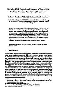
specializing the existing classes. Via specialization the modeler can modify the default values of the attributes of the base classes, or introduce new operations. For instance, Figure 8 shows a fragment of class diagram where a specialization of a HumanActivity is shown. Such specialization describes a testing activity performed within the context of the software development process presented in Section 6. Notice that a new attribute and a new operation are introduced. At the level of the class diagram, the process modeler can also define “part of” relationships between activities and the corresponding subactivities, or between groups and the agents that compose them. Also, he/she can decide to specialize the state diagram inherited by the base class. Before focusing on state diagram specialization, let us provide some details on the structure of OPSS-compatible state diagrams. Each transition in a state diagram must be adorned with the following elements: InputEvent(arguments)[Guard]/[Action]/[OutputEvent(arguments)] InputEvent is the name of the event that will trigger the transition. During process execution, such event is then reified in a JEDI event. The specification of the event is mandatory: otherwise at run time it would be impossible to determine when the transition has to be actually triggered. The specification of the event may include a number of parameter names, which have to correspond to some attributes in the class definition. For instance, in the fragment of state diagram associated to activity Test shown in Figure 4 the input event called SuspendActivity has an argument, instanceNumber, which corresponds to an attribute of class Test. At runtime, given an instance of class Test, the event Suspend triggers the corresponding transition if and only if the argument instanceNumber associated to the event is equal to the value of the same attribute of that specific instance. setResult(instanceNumber)/ ErrorFound = getResult(evt) Active
Suspend (instanceNumber)
Suspended
Figure 4. A state diagram fragment of activity Test. All remaining elements belonging to the specification of a transition are optional. They are:
In this section we intuitively present the way we use UML for process modeling. A formalization of the constructs, extensions and constraints adopted is given in Z [17] and it is not reported here because of space constraints.
•
A Guard: a boolean expression over the current state of the associated entity and/or the structure of the InputEvent. The Guard can contain calls to operations defined as part of the entity itself.
The diagrams we adopt for process modeling are the activity, class, and state diagrams. In particular we use the activity diagram, as usual, to describe the flow of activities in the process and the association between activities and agents executing them. A few refinements of the constructs of activity diagrams are presented later in this section.
•
An Action containing any Java statement, including a call to an operation defined as part of the entity. Such operation can have one or more parameters as usual. One of these –denoted by the name evt– can be the input event that has triggered the transition. Clearly, the signature of the operation, as it is described in the associated class description, has to be coherent with the call. The type associated to events in the signature and the body of the operation is JEDIevent. Figure 4 shows an example of action where a value is assigned to attribute ErrorFound. Such a value is computed by calling the getResult method.
•
An OutputEvent. At runtime this is generated as a result of a state transition. In this case the argument list contains expressions whose values are transmitted with the event.
We use class diagrams to associate concepts belonging to the level of the process description with concepts that are part of OPSS and that are reified in the State Server. In particular, we provide the process modeler with a number of predefined classes that describe in UML the process entity representatives (activities, agents, resources, artifacts, and their subclasses). Such classes have associated a state diagram that describes in UML the life cycle of each entity. A process modeler willing to use OPSS has to start defining his/her own activity types, agent types, etc. by
Each state diagram is required to contain an initial state, denoted according to the usual UML notation, and may contain one or more final states. At runtime, whenever an entity gets to its final state, it is eliminated from the state server. Being a general-purpose language, UML does not define specific rules for state diagram specialization. Indeed, in the specification of UML version 1.3 three possible specialization approaches are described [15]. Among them we chose the method called subtyping: intuitively, given a state diagram A, the state diagram B can be considered as a specialization of A if: •
B defines new states and transitions, but it does not eliminate the states and transitions existing in A. For instance, in Figure 4 the state diagram of HumanActivity has been specialized with respect to Figure 3 by adding the transition from the state Active to the same state.
•
B refines one or more states of A by means of proper state diagrams. For instance, Figure 5 shows the specialization of a fragment of the state diagram associated to Agent. Such a specialization is associated to HumanAgent and accounts for the fact that a human being, besides being available or not to take care of an activity, may also be temporary not logged into the system. Notice that when a state is expanded, the transitions associated to it can be specialized to identify the substates they are connected to: see for instance the transition triggered by the event DeallocateAgent. Since we assume that an agent can terminate an activity only if he/she is working, he/she has to be logged to issue the completion of the activity that, in turn, triggers this event. In Figure 5 ra stands for requested allocation or released allocation, ca for current allocation, Ma for maximum allocation. The last two ones are attributes of Agent (see Figure 10). Not Available
Not logged Login(agentName) Logout(agentName) Logged
AllocateAgent(ra) [ra+ca≥Ma]
Available
DeallocateAgent(ra)/ ca=ca-ra
Not logged
AllocateAgent(ra) [ra+ca≥Ma] DeallocateAgent(ra)/ ca=ca-ra AllocateAgent(ra) [ra+ca≥Ma]
AllocateAgent(ra) [ra+ca