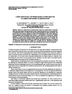
Design Algorithms for Multi-zone IP Address Caches Michael H. MacGregor Dept. of Computing Science, University of Alberta, Edmonton, Alberta, Canada T6G 2E1 Email:
[email protected] Abstract—The multi-zone cache is a new architecture for IP address caches that has been shown to have significantly better performance than standard single zone caches in this application. This new architecture presents three more degrees of freedom when specifying a design, in addition to the size of the cache. These are the number of zones, the size of each zone, and the range of prefix lengths of the addresses cached in each zone. In this paper we present analytical models that can be used to make decisions about these values. Index Terms—cache memories, IP address, routing, design methodology.
I. INTRODUCTION
T
HE scalability of the Internet, and networks in general, is determined in large part by the rate at which the routers and switches in the network can make forwarding decisions. Significant progress has been made in the area of improved algorithms for finding the route with the maximum length prefix that matches the destination address of the packet to be routed (see for example [1]). To maximize the forwarding rate of a router, however, we should only make reference to such an algorithm when absolutely necessary. The results of recent routing decisions should be cached in hardware, and this cache should be checked before resorting to a softwarebased lookup. When the cache reference is successful, the forwarding decision can be made completely in hardware, at the speed of SRAM. As has been shown elsewhere, IP address caches of moderate size can have very good hit rates[2]. Even a cache hit rate of “only” 90% is significant in the routing application because this level of performance reduces the rate of software lookups by an order of magnitude. It can also have a marked effect on router latency and internal queue lengths. Still, if a particular cache hit rate is not high enough to meet design requirements, it is often the case that simply increasing the size of the cache will improve the hit rate. However, the increase in cache hit rates diminishes as the cache increases in size. The quantitative point at which this limit becomes apparent depends on the locality properties of the reference This work was supported in part by the Natural Sciences and Engineering Research Council of Canada.
stream. Once this point is reached, however, something new is needed. One possibility that has been suggested recently is to change the architecture of the cache, by splitting it into multiple regions or “zones” [3]. This new architecture has been shown to improve hit rates, specifically in this region of diminishing returns, as well as more generally throughout the range of cache sizes. II. ARCHITECTURE AND DESIGN OF THE MULTI-ZONE CACHE The motivation for the multi-zone cache comes from the observation that a large proportion of the destination addresses seen at a router interface comes from a small part of the IP address space. This is true both in terms of the raw destination IP addresses, as well as in terms of the prefix lengths of the routes for these addresses. For example, a particular interface may see a large number of addresses with 24 bit prefixes, due to the preponderance of Class C (or CIDR /24) address allocations. Another router, perhaps facing a set of residential subscriber networks, might see mostly addresses with 30-bit prefixes. In circumstances like this, cache hit rates will be improved by allocating most of the space in the cache to the prefix lengths that are seen most often. The cache is populated using the results of software routing-table lookups. When a software routing-table lookup completes, it returns the output port plus the prefix length of the matching route. The result of the lookup is then stored in the region of the cache – called a zone here – allocated to prefixes of the length of the matching route. One relatively simple organization that has been tested so far is to keep contiguous ranges of prefix lengths in the same zone. For example, the cache could be divided into two zones, with addresses whose routes have prefixes less than 25 bits in length being stored in one zone, and addresses whose routes have prefixes 25 bits or longer being stored in the other zone. A. The Cache Design Problem: Single-Zone Case The design variables for a conventional single-zone IPaddress cache are degree of associativity, number of cache lines, and the size of each line. IP address caches are small enough that the cache can be fully associative, so that removes one design variable. The number of cache lines is the prime design variable because line size is fixed by the format of an IP address plus the format of the internal specifier for
the selected output port. As a first approximation, if we allow for a router to have up to 1024 interfaces, then cache lines of 42 bits will be sufficient – 32 bits for an IPv4 address, and 10 bits to denote the outbound interface. Thus, for a conventional single-zone IP-address cache, the design problem devolves into choosing the number of cache lines. B. Designing a Multi-zone Cache Selecting a multi-zone design means that choices must be made for the number of zones, the prefix lengths of the addresses kept in each zone, and the number of cache lines in each zone. As with the single-zone cache, full associativity will be used to maximize hit rates, and the address and interface identifier formats will set the size of each line. The design space can be simplified by assuming that contiguous prefix lengths will be kept in each zone, and that all possible prefix lengths will be covered by the cache. If we assume the designer has a fixed amount of fast memory available to be used by the cache, then the problem can also be simplified by assuming that we have a known, fixed cache size. The central feature of the design problem is that of predicting the hit rate of a cache zone of known size, containing addresses with a given range of prefix lengths. Once the hit rates of the individual zones are known, the global hit rate can be calculated. The hit rate of an individual zone must be evaluated with reference to the traffic that will be seen by the cache because the locality characteristics of IP destination address streams change tremendously depending on the location at which the traffic is observed. We concentrate in this paper on a general method for multi-zone cache design that is independent of the statistical character of any individual trace. Other research is in progress to develop general models for IP address traces [4]. One method for characterizing reference stream locality is the footprint function proposed in [5]. If n is the sequence number of a reference in a stream of references (e.g. the nth packet in a stream of IP packets) then the footprint function u(n) gives the number of unique references in the stream up to that point. For example, if u(120)=14 then at the time of arrival of packet 120, including packet 120, we have seen 14 unique destination addresses. Thiebaut et al [5] propose that the footprint function be fitted by regression using:
u = An1/ θ
(1) They also note that the miss rate for a cache of size C is the value of the first derivative of the footprint function at the point that u(n) = C. Clearly, a cache of size C will contain at most C addresses, and each address will be unique because the cache will maintain only a single entry per address.. The rate at which new unique addresses arrive in the reference stream, giving rise to cache misses at that same rate, is the first derivative of u(n) at a cache size of C. The inverse of Eq. (1) is:
n = (u / A)θ
(1’)
The derivative of (1) is: 1
A ( −1) A du / dn = n θ = n θ θ
1−θ θ
(1’’)
Substituting 1’ into 1’’ we have: θ A u du / dn = θ A
1−θ θ
A u = θ A
(1−θ )
Aθ (1−θ ) = u θ
If we denote the value of the first derivative - the miss rate as m(C), and evaluate it at the point u = C , where C denotes the cache capacity, then we have:
Aθ (1−θ ) m (C ) = C θ
(2)
A serious shortcoming of the original footprint function now becomes apparent: in reality, the cache miss rate must be identically 1 when C=0 because if the cache capacity is zero then all references must be misses! However Eq. (2) cannot supply this behavior because it is obliged to predict a miss rate of zero for a cache size of zero, which is nonsensical. This problem is easily corrected: if we modify the function slightly, substituting (C+1) for C, then the function can θ
produce a miss rate of 1 when C = 0 as long as A / θ = 1 . With this change Eq. (2) becomes:
m(C ) = (C + 1) (1−θ )
(3)
Integrating and substituting we find that we should use:
u(n ) = (θn ) (1 /θ ) − 1
(4)
to fit the footprint function. With this single-parameter model we can be sure that the miss rate will behave sensibly as the cache size decreases. As an example, we present the data in Fig. 1. Here we have used an IP address trace obtained from a campus gateway at the University of Alberta (U of A). There are one million packets in the trace, and we have used the footprint function from the first 10,000 packets to fit the parameters for the models of Eq. (1) and Eq. (4). At cache sizes below about 500 lines, the two-parameter model fits the observations very poorly, and in fact has a slope much greater than 1.0 (implying miss rates in excess of 100% !). In contrast, the one-parameter model fits the observations very well in this range, and exhibits the correct slope as it approaches C=0. C. An example two-zone design Almost 25% of the references in the U of A trace are to destinations whose prefixes are 23 bits in length. This suggests using a cache with two zones, where addresses whose prefixes are 22 bits or shorter are kept in zone 1 and
addresses whose prefixes are 23 bits or longer are kept in zone 2. We split the 10,000 packet subtrace by prefix length, and fit Eq. 4 to these two portions. For the portion with addresses whose prefixes are 22 bits and less we find θ = 1.3538 and for the portion with addresses whose prefixes are 23 bits and longer, we find θ = 1.6915 . The design problem is to find the best allocation of cache lines between the two zones while keeping the total number of cache lines fixed. Based on other considerations we selected a total cache size of 400 lines. This particular problem instance is simple enough that exhaustive search can be used, requiring only 400 evaluations of the global hit rate. To validate the model predictions we also used a simulation to measure the hit rate of 39 cache configurations, beginning with 10 lines in zone 1 and 390 lines in zone 2, and then increasing the allocation to zone 1 by 10 lines (and decreasing the allocation to zone 2) until zone 1 reached 390 lines in size. The predictions and measurements are shown in Fig. 2. Firstly, it should be noted that the predictions in Fig. 2 are based on the parameter values from a 10,000 packet subsample while the measured values from the simulation are based on the full one million packet trace. This was done in order to test whether the parameter values for the footprint function yield reasonable predictions for the entire trace. The model holds reasonably well, based on the match between the predicted and measured values. The predicted optimum is at 320 lines in zone 1, with a predicted global hit rate of 0.8922, while the measured optimum is at 330 lines in zone 1 with a global hit rate of 0.9211. The absolute values of hit rate are quite close, and the location of the optimum agrees to within the step size (10 lines) of the simulated cache configurations. D. Optimization Tableau The multi-zone cache design problem can be formulated as a constrained integer nonlinear optimization problem. Considering the case of a two-zone design first, we have:
min( ∑ Fi mi (C i )) k
subject to: B
F1 = ∑ f i
F2 =
i =1
mi (Ci ) = (Ci + 1)
∑C
32
∑f
i
i = B +1 (1− Φ i )
=C
i
k
p j ∈ {0,1} , j=1..31
∑ p =1 B = ∑ jp j
j
Φ 1 = ∑ p jθ j
Φ 2 = ∑ p jθ ′j +1
where k = 2 . F1 is the fraction of references to zone 1, and F2 is the fraction of references to zone 2. fi is the fraction of
references with prefixes of length i. pj selects the prefix lengths for zone 1, and B is the maximum prefix length for zone 1. θj is the parameter for the footprint function of references with prefixes up to length j, and θ’j is the parameter for the footprint function of references with prefixes of length j and greater. We assume that a given reference falls into only one zone. The tableau for caches with more than two zones is only slightly more complex, but there are some added constraints due to the additional breakpoints in prefix length. In the case of a cache with four zones, we let:
B1 = ∑ jp1, j
B2 = ∑ jp 2 , j
B3 = ∑ jp3, j
denote the prefix lengths of zones 1, 2 and 3 respectively. Zone 4 caches addresses whose prefixes are from (B 3+1) to 32 bits long. We also add:
B1 < B2
B2 < B3
to establish the ordering of the zones. Finally, we need parameters for the footprint functions of the two middle zones:
Φ 2 = ∑∑ p1, j p2,kθˆ j ,k −1
Φ 3 = ∑∑ p2, j p3,kθˆ j ,k −1
where θˆ j ,k is the parameter for the footprint function of references with prefixes from length j to length k, inclusive. The constraint for Φ 1 is similar to that for Φ 1 in the twozone case, and the constraint for Φ 4 is similar to that for
Φ 2 from the two-zone case. Pragmatically, due to the increasing complexity of controlling a cache with many zones, it is unlikely that a design with more than four zones would be used. However, the optimization tableau for such a design is a simple extension of the four-zone case. It is possible to write the optimization tableau for the general case, and optimize the number of zones as part of the tableau, but it is much less complex to solve the two, three and four-zone designs separately. This also quantifies the incremental benefits of using extra zones. The optimization surface for the design of a two-zone cache for the U of A trace is presented in Fig. 3. The vertical axis is global hit rate. The best design has a global hit rate of 0.933, and allocates addresses 382 lines to zone 1, where it keeps addresses with prefixes of 23 bits or less. This should be compared to the hit rate of the conventional single-zone cache, which is 0.851. The optimal three-zone design for the U of A trace has a hit rate of 0.958, and keeps addresses whose routes have prefix lengths of at most 11, 22 and 32 bits in zones 1, 2 and 3 respectively. The cache allocation is 126 lines in zone 1, 190 lines in zone 2 and 84 lines in zone 3. The optimal fourzone design for the U of A trace has a hit rate of 0.979, and keeps addresses whose routes have prefix lengths of at most 11, 13, 22 and 32 bits in zones 1, 2, 3 and 4, respectively. The cache allocation is 134 lines in zone 1, 78 lines in zone 2, 89
lines in zone 3 and 99 lines in zone 4. For a hypothetical million packet-per-second interface, the conventional cache reduces the software lookup rate to under 150 thousand packets per second, and the four-zone cache reduces the software lookup rate to about 20 thousand packets per second. The cost of this improvement is relatively trivial, being on the order of 12,000 bits of fast memory plus associated control. III. SUMMARY The one-parameter footprint function proposed here corrects a fundamental flaw in the model proposed by Thiebaut et al for the locality of reference streams. The new function proposed in Eq. (4) results in the correct limiting behavior for cache miss rates as cache size approaches zero, whereas the earlier proposal predicts miss rates of zero for caches of size zero. This correction is extremely important in the present context, because this model is intended to be applied in the context of finding a cache design that minimizes the predicted miss rate. Any capable optimization routine, confronted with a function that predicts no cache misses for a cache of size zero will relentlessly drive the solution to exactly that point. The revised model should be considered when predicting cache miss rates, both for the specific case of IP-address caches, and for general-purpose CPU caches, because the one-parameter model in Eq. (4) has the correct limiting behavior, predicting a cache miss rate of 100% for a cache of zero size. The optimization tableaus presented here can be used in concert with this revised model to find optimal designs for multi-zone IP-address caches. It is also possible to use a gradient-based search that starts from a preliminary configuration and then optimizes over the zone prefix lengths first, followed by optimization over the space allocations to each zone. Iterating between these two sets of co-ordinates has been found to result in quick convergence.
Our further work will consist of comparing the results from the integer programming tableaus with those from the gradient search on a variety of parameterized IP address traces, and in exploring various special cases in the design space. In addition, we are testing the practicality of the multizone approach by prototyping a multi-zone address cache using Xilinx FPGAs. Our current design appears to have sufficient throughput to meet the needs of a single OC48/STM-16 interface, and we are hoping to use the VHDL description to produce a subsequent design based on custom cells, thereby appreciably improving the maximum address lookup rate of the cache. REFERENCES [1] [2] [3] [4]
[5]
M. Degermark, A. Brodnik, S. Carlsson, S. Pink, “Small Forwarding Tables for Fast Routing Lookups”, Proc. ACM SIGCOMM ’97, pp.3-14. T. Chiueh, P. Pradhan, “High Performance IP Routing Table Lookup Using CPU Caching”, Proc. IEEE Infocom ’99, pp. 1421-1428. I. Chvets, M. MacGregor, “Multi-zone Cache for Accelerating IP Routing Table Lookups”, Proc. HPSR ’02, pp. 121-126. W. Shi, M. MacGregor, P. Gburzynski, “Effects of a Hash-Based Scheduler on Cache Performance in a Parallel Forwarding System”, Proc. Comm. Net. and Dist. Sys. Modeling (CNDS 2003), pp. 130-138. D. Thiebaut, J.L. Wolf, H.S. Stone, “Synthetic Traces for Trace-Driven Simulation of Cache Memories”, IEEE Trans. Computer, 41(4), April, 1992.
u(n)
500 450 400 350 300 250 200 150 100 50 0
Observed 2 parameter fit 1 parameter fit
0
250
500
750
1000
1250
1500
n Figure 1. Models for the footprint function – U of A trace
Global hit rate
1 0.8 0.6
Predicted Measured
0.4 0.2 0 0
100
200
300
400
# of lines in zone 1 Figure 2. Global hit rate – Predicted vs. Measured
0.95 0.9 0.85 0.8 0.75 0.7 0.65 0.6 0.55 0.5 0.45
0.95 0.9 0.85 0.8 0.75 0.7 0.65 0.6 0.55 0.5 0.45
350 300 250 200 150 Zone 1 size 100
25 20
Zone 1 prefix length
15 50
10 5 Figure 3. Two-zone optimization surface
0