Iranian Journal of Science & Technology, Transaction B, Engineering, Vol. 29, No. B1 Printed in The Islamic Republic of Iran, 2005 © Shiraz University
THREE NEW NEURAL NETWORK BASED ALGORITHMS FOR * IP LOOKUP AND PACKET CLASSIFICATION M. MAHRAMIAN1**, N. YAZDANI2, H. TAHERI1 AND K. FAEZ1 1
Faculty of Elec. Eng., Amirkabir University of Technology, Tehran, I. R. of Iran Email:
[email protected] 2 Faculty of Elec. Eng.,Tehran University, Tehran, I. R. of Iran
Abstract– Routers use lookup tables to forward packets. They also classify packets to determine which flow they belong to and what quality of service (QoS) they should receive. Increasing the rate of communication links is in contrast to the practical processing power of routers and switches. We propose some neural network algorithms to solve the IP lookup problem. One of these algorithms, back propagation, gives promising results; however, it has problems in training time. Another algorithm, a 12 layer neural network, represents acceptable results on error rate and training time. Parallel processing of neural networks provides huge processing power to do IP lookup. The algorithm can be implemented in hardware on a single chip. Our method can perform an IP lookup in 4.5 nanoseconds, which implies the support for a 60 Gbps link rate. Pipelining and parallel processing can be used to increase the link rate up to 400 Gbps and also decrease the learning time. Keywords– IP lookup, packet classification, neural network, ART1, back propagation
1. INTRODUCTION IP lookup and packet classification are the bottlenecks of the high speed networks. Communication links have increased their baud rates up to a terra bit per second, but the processing speed has not been improved at the same rate. Fiber links are potentially able to transfer billions of packets in one second, but a switch or router can not process them in the same time. Expanding the size of the global network increases the size of the lookup tables. On the other hand, increasing communication line speeds requires a reduction in the processing and search times since the packets must be switched at the wire speed. This implies that the forwarding engines need a more efficient IP lookup technique [1]. Routers perform a forwarding decision on the incoming packet to determine the next-hop. This is done by examining the destination address of a packet, finding the longest matching prefix in the forwarding lookup table and then forwarding the packet to the corresponding next hop. Increase in packet arrival rates at higher speed links, the complexity of the lookup mechanism and the size of forwarding tables have made IP lookups a bottleneck [2]. Packet classification is critical in supporting QoS and security in the data networking. The objective is to identify the highest priority rule that applies to an incoming packet. The rules are typically defined over multiple fields of the packet header and each rule specifies operations to be performed on a particular category of packets [3]. Most of the present solutions to packet classification make a transformation from IP lookup domain to packet classification domain [3-14]. Thus, an extendable fast algorithm for IP lookup can solve the packet classification problem. Any lookup or classification algorithm must satisfy some requirements [2]. First, it must be fast in searching to support high speed communication links. Implementation comes next. It also should have low update and initialization time. A neural network is rarely used for packet classification and IP lookup. Tan [15] tries to process the traffic of a network to detect the presence of unauthorized and anomalous network services [15]. He ∗
Received by the editors January 13, 2003 and in final revised form January 24, 2004 Corresponding author
∗∗
12
M. Mahramian / et al.
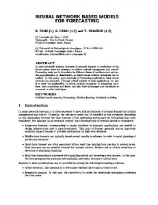
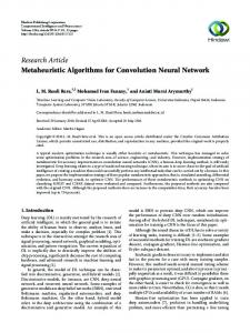
proposes a neural network to develop a network connection signature for common network services. This allows connection type recognition to be independent of the port information. Neural network algorithms are generally flexible and fast. They can be implemented using parallel processors. They require distributed memory architectures which result in reduced access time to the memory since they can be accessed in parallel. By increasing the number of hidden layer neurons, neural networks can learn large routing tables [16]. Training time is the main issue in neural networks. Usually, it takes a long time for a neural network to learn all input patterns. The update rate of neural networks is another problem [17]. Our third algorithm in this paper has fairly solved these problems. The rest of the paper is organized as follows. Section 2 describes the IP lookup problem. In section 3 we explain ART1 and its application to IP lookup. Section 4 continues with back propagation networks and simulation results. We applied the architecture to the different types of back propagation networks in this section. Our solutions for updating and initialization difficulties are also explained there. The last algorithm is presented in section 5. Implementation issues including architecture of the VLSI circuit and neurons are investigated in section 6. Section 7 concludes the paper and contains the future work. 2. BACKGROUND The proposed approaches for the IP lookup problem are usually classified in four categories [18]. The first category includes methods which usually modify exact matching schemes and apply them to the prefix matching problem. We include the trie-based schemes in this category. The methods are many including the M-Way prefix tree and binary prefix tree [1], Ranged search tree, Patricia trie, Dynamic Prefix trie [19], Level compression trie [20], Multiway and multicolumn search [21], DIR-24-8-BASIC scheme [22], Multilevel prefix tree [23] and some others. The second category contains hardware based solutions. They usually use CAM (Content addressable memory). In CAM, the content of each memory location is compared in parallel to the input key and data in the matching location is put on the output. This is a relatively fast, but expensive solution [24, 25]. The third category contains protocol-based like MPLS and TAG switching solutions. These methods translate the prefix matching problem into the exact match. In these methods, we need to modify the packet headers. Furthermore, not all of the existing networks support these protocols and we will face difficulties in applying those to all points of the global network. Furthermore, we still need IP lookup at the ingress or entry points to the network. Finally, the last category of solutions is caching. This solution is also expensive, like CAM, and cannot be used for large IP lookup tables. In the neural network algorithm, we train the neural network and apply all of the prefixes to the network. After the learning phase, each IP address enters the network and the next hop address appears at the output of the network. Figure 1 shows the block diagram of the system. This is a simplified view of the network. IP packets enter from input ports of the switch and the corresponding destination address, which specifies the output port that the packet should be forwarded to, appears at the output of the neural network. There is a module for training and a memory for managing updates.
Output port with longest prefix match
IP ADDRESS
Fig. 1.The block diagram of a neural network IP lookup system Iranian Journal of Science & Technology, Volume 29, Number B1
February 2005
Three new neural network based algorithms for…
13
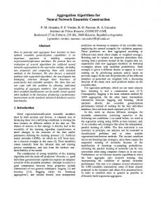
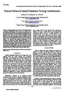
We propose one supervised and two unsupervised neural networks for IP lookup. ART1, back propagation and a new multi layer algorithm based on back propagation. The first solution, the unsupervised one, classifies the IP addresses itself. The second and third ones use supervised algorithms. Each new IP address is trained to the neural network in the training phase, as well as its next hop [26]. ART1 finds IP addresses with a similarity higher than a threshold value and categorizes them in a class. With similarity we mean that the difference between two IP addresses is less than a threshold value. If a new IP address can not be assigned to any previous class, we define a new class and put the new IP address in this class. Each class corresponds to one of the next hops. Indeed, we use the fact that there are few output ports in a router and each output corresponds to the next hop. Therefore, all packets that go to the same output can be treated in the same way. This is exactly the idea of forwarding equivalence class (FEC), which is used in MPLS [27]. Our simulation results show that ART1 and other unsupervised neural networks are not suitable for the IP lookup problem. Contrary to ART1, the back propagation algorithm works well; however, it is slow in initialization and updating (i.e. the insertion and deletion of IP prefixes). We tune the algorithm to make it suitable for IP lookup at very high speeds. Finally, a new multi layer neural network is proposed to solve training and updating problems. Links running at 60 Gbps rates can deliver 200 million packets per second (assuming minimum-sized 40 bytes TCP/IP packets) [2]. Therefore, routers connected to these lines must forward each packet in 5 ns. Our algorithm can accept a new packet every 4.5ns. So it can forward 200 million packets in a second. The proposed network can be implemented in a single chip. We investigated a fast multiplier for the links and our calculations show that it can be implemented in an IC (ASIC or FPGA). 3. IP LOOKUP AND ART1 Carpenter and Grossberg developed adaptive resonance theory (ART) in 1987. ART1 is one of the ART forms which is designed for clustering binary vectors [28]. Another one, ART2, accepts continuous valued vectors [29]. These nets cluster inputs by using unsupervised learning. Each time a pattern is presented, an appropriate cluster is chosen and the cluster weights are adjusted to let the cluster unit learn the pattern. Figure 2 shows the architecture of an ART1 neural network. This architecture consists of input layer S, interface layer X, cluster units Y and reset unit R. Input IP addresses are applied to the network from the S layer. The weights between input and interface layers are 1, so the IP address is transferred to the interface layer. Then the learning algorithm decides whether this input is most similar to any cluster in the output layer via some iteration. The reset unit implements user control over the degree of similarity of patterns placed on the same cluster. If the reset unit activates, it means that the last input should be placed in a new cluster, so it is similar to none of the existing clusters. For more information on the algorithm and the structure, an interested reader can refer to [17, 30].
Fig. 2. Structure of ART1 neural network
The size of the input layer is dictated by the IP address length, i.e. 32. The output layer size is determined by the number of next hops (output ports of the switch) and ART1 decision. February 2005
Iranian Journal of Science & Technology, Volume 29, Number B1
14
M. Mahramian / et al.
a) ART1 results IP addresses, which are inputs to the system, are 32 bits and all of the IP addresses matching an IP prefix are applied to the neural network. For example, if the prefix was 192.168.18.* all of the 256 IP addresses from 192.168.18.0 to 192.168.18.255 were applied to the network. Inputs and outputs were bipolar. The threshold value (ρ) varied from 0.75 to 0.99. Unfortunately, the number of clusters is too large and the algorithm needs a huge number of output neurons for clustering IP addresses. The maximum number of clusters is set to 100. Input data for the training phase is the same as data in the application phase. The IP prefixes that are applied to this network are: 'fffff***' , '11e1f***' , '01e1f***' , '00d13***'
Each prefix contains 212 = 4096 IP addresses. Thus, 4 * 4096 = 16384 IP addresses are as inputs for training. The simulation results indicate that the network needs more than 100 clusters for classification of 4 IP prefixes. Assuming core routers with ten thousand IP prefixes (e.g. 100K), this network will not work. The problem arises from the fact that the algorithm is unsupervised. The network itself decides the cluster for each IP address and this causes a large number of clusters. The unsupervised algorithms may not classify IP addresses with the same prefix in the same class and this may cause a huge number of classes. 4. IP LOOKUP AND BACK PROPAGATION
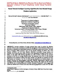
Back propagation (BP) is simply a gradient descent method to minimize the total squared error of the output computed by the net. Although a single-layer net is severely limited in the mapping it can learn, a multi layer net can learn any continuous mapping to an arbitrary accuracy. The structure of the back propagation network is shown in Fig. 3. The BP neural networks used in this study are three layered feed forward. The length of the IP address, 32 bits, dictates the size of the input layer (i.e. number of input layer, X in Fig. 3). The number of available next hops is represented in the IP switch, each output unit representing one output port, determining the output layer size (i.e. Y in Fig. 3). The hidden unit size (i.e. number of Z units in Fig. 3) in the first step is ten. We use the Hecht-Nielsen theorem [17] for an optimized and reliable number of hidden neurons. The theorem says that any continuous function f : I n → R m , where I is the closed unit interval [0, 1], can be represented exactly by a feed forward neural network having N input units, 2N + 1 hidden units and M output units. Thus we chose 2 * 32 + 1 = 65 for the number of hidden neurons. A bipolar input and output and bipolar sigmoid activation function are used. If input IP address is C4(Hex), the input of BP network will be +1+1-1-1-1+1-1-1, which is applied directly to the X layer of the BP network. Nguyen-Widrow initialization [17] is used for initialization of the first and second layer weights. Biases in both layers are assumed. The operations of the present neural IP lookup system consist of two stages: the learning stage, during which the system learns IP prefixes; and the retrieving stage, during which the system retrieves IP addresses after being presented. At the learning stage, IP prefixes are presented to the input channels of the system. For example, let the IP prefix length be 2 (n = 2) bits and number of units in the hidden layer be 2 (p = 2) and number of output units be 2 (m = 2). Weight matrices are V and W. V is a (n+1)*p matrix. It connects the input layer to the hidden layer. W is a (p+1)*m matrix which connects each unit of hidden layer to the output layer. If IP address = [+1 –1] appears at the input of the neural Table 1. Simulation results for back propagation network in different configurations Config.
N
p
m
1 2 3 4
32 32 32 32
10 10 10 10
8 8 8 8
No. of iterations 70 70 50 100
Mean squared error. 1625.4 450.2130 1658.2 562.4514
Iranian Journal of Science & Technology, Volume 29, Number B1
Critical IP routing error. * * 255 6
IP routing errors. * * 255 6
Total IP addresses 2304 2304 2304 2304 February 2005
Three new neural network based algorithms for…
15
1.2 − .3 − .2 .85 V = 1.9 .6 , W = − 1.5 − .9 .03 − 1.7 2.1 − 1.4 the input of the hidden layer will be a Z matrix calculated by Zi=[1IP]*V
(1)
Outputs of the hidden units are determined by a built-in activation function f(⋅) like a bipolar sigmoid function (2) (Zo = f(Zi)) Oi vector represents output of output layer (Oi = [1 Zo]* W)
(3)
Fig. 3. Back propagation network architecture
Another activation function brings the output vector O. If the input packet should be forwarded to the first output, then we expect a [+1 –1] for the output vector. During the learning phase, weights in V and W are changed, so we can have the desired output vector for each input IP address. In the retrieving phase, the incoming packets’ IP addresses are applied to the neural network and the network decides the next hop using the multiplication, summation and activation functions (Eqs. (1-3)). Figure 4 shows the block diagram of application network. We will explain more about different parts of this block diagram. We proposed different schemes for structure and configuration of a back propagation neural network. Table 1 shows simulation results. Configuration number 1 is a back propagation neural network in which the inputs and outputs are binary. All IP addresses matching a prefix are used as inputs to the neural network for training. For example, if we have an IP prefix, 192.168.18.*, all IP addresses from 192.168.18.0 to 192.168.18.255 are inputs to the network. Configuration number 2 is similar to the first one, except that the IP prefixes are sorted in the IP lookup table so that the longest prefix comes at the bottom of the table. The error is decreased in this case, as shown in Table 1 and Fig. 5. Mean square error in the same configuration, however, in a random order for IP prefixes, is shown in Fig. 6. In the next configuration, bipolar inputs and outputs are used and we place *s by 0s in prefixes. The training time is decreased in this configuration, but the network routes 255 packets to a wrong next hop. There were 2304 packets, so we have more than 10 percent errors and this is not acceptable. In configuration 4, bipolar inputs and outputs are used and all IP addresses matching a prefix are used as inputs to the network during the training phase (Like config. number 1). This configuration has the best results, i.e. only 6 errors in 2304 packets (see Figs. 7 and 8). This implies a less than 0.2% error in routing. Of course, errors in routing are not acceptable. Fortunately, with optimizations in the algorithm, we can improve the error rate. Other configurations were tested, but none of them reached a better result. In one of these configurations we omitted the parts of weights that are related to *s of the prefix under the training. Then we tried m parallel networks, where m indicates the number of output ports. Each network belonged to one of the output ports and had two output nodes. February 2005
Iranian Journal of Science & Technology, Volume 29, Number B1
16
M. Mahramian / et al.
As a matter of fact, each network decided whether the input IP address belonged to this output port or not. But there is a problem here; what will happen if an IP address matches more than one output port? We expect the longest prefix that matches the IP address to produce a higher output, but the simulation results showed a random behavior from the network. Figure 9 shows the results of simulation.
Fig. 4. Block diagram of fast IP switch
n=32, m=8, p = 10
Fig. 5. Mean square error during training phase versus number of iterations. IP prefixes were sorted before training
n=32, m=8, p = 10
Fig. 6. Mean square error during training versus number of iterations. (Configuration number 4)
The configuration number 4 is selected for the final circuit since it has the minimum error. The IP lookups are updated almost every 30 seconds. For compensation of high training time we duplicated the architecture. One of the neural networks is used for the application and another for training (Fig. 4). During the training, new IP addresses may enter the IP lookup, but the application neural network is not trained for Iranian Journal of Science & Technology, Volume 29, Number B1
February 2005
17
Three new neural network based algorithms for…
these IP addresses. A small traditional IP lookup is used parallel to the application neural network. During update and training, a traditional IP lookup scheme routes the IP addresses that match the new IP prefixes. Application neural network routes these IP addresses too, but the output of traditional IP lookup has the highest priority and can override the result of the application network. After training, the traditional IP lookup will be disabled.
n=32, m=8, p = 10
Fig. 7. Mean square error during training phase versus number of iterations. Order of inputs is randomized
n=32, m=8, p = 10
Fig. 8. Number of IP routating during training versus number of iterations. (Configuration number 4)
(a) (b) Fig. 9. Outputs of networks with two prefixes with different lengths. One of the prefixes is a prefix of the other. All IP addresses match with both networks. We expect that the longest match gives the maximum output. Test (a) supports this, but test (b) does not. In test (b), half of IP addresses route to the longest prefix match and half of them route to the shortest prefix match
5. A MULTI LAYER NEURAL NETWORK
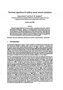
The most serious problem of the back propagation network in section 4 is training time. We proposed some heuristic algorithms to solve the problem, but they may cause some routing errors. This may cause a packet to never reach its destination. To solve this problem, a new algorithm which uses four back propagation networks is proposed. Each network will be trained separately, therefore the size of training for an IP prefix is limited to 256. Figure 10 shows the architecture of the network. As a matter of fact, the network contains 4 cascaded back propagation networks, each trained separately and in parallel. Using a simple back propagation algorithm, the network should learn 2 (32 − k ) IP addresses, where k is the length of IP prefix (e.g. 65536 IP addresses for a 16 bit long IP prefix). In the new multilayer network, at most 896 (3 * 256 + 128) IP addresses will be trained to the network for a 1 bit IP prefix. The IP prefix 101.229.5*(H).* is divided into 4 eight bit parts: 101, 129, 80:95, 0:255, and each of them is applied to one of the back propagation networks. Thus, the first and the second networks learn one input number, but the third and the fourth February 2005
Iranian Journal of Science & Technology, Volume 29, Number B1
18
M. Mahramian / et al.
networks learn 15 and 256 input numbers, respectively. In the application 0phase, the IP address of the input packet is applied to the four back propagation networks. Output of the first network is applied to the input of the second network, and so on. The output of the fourth network determines the next hop. What happens when some of IP prefixes have some equal parts, e.g. 101.129.*.* and 101.129.15.*? In this case, a preprocessing phase is performed in a way that each IP address goes to the output port with the longest match. In other words, the third network learns 15 with the output port of 101.129.15.* and all other 255 numbers (0:14, 16:255) with the output port of 101.129.*.*. In the same way, the fourth network learns all 256 numbers, one time with the output port of the second one.
Fig. 10. A 12 layer neural network based on four back propagation networks. Each network gets 8 bits of IP prefix. Training is done in parallel
To obtain a uniform training time in 4 back propagation networks, the total number of inputs multiplied by number of iterations is considered as a constant, thus the numbers of iterations for 4 networks are chosen in a decreasing order, e.g. 2000, 50, 25, 6. Tables 2 and 3 show the results of simulation. The simulation was performed 24 times with different parameters, 12 of those were repeated simulations to evaluate the repeatability of the results (Table 2). It can be seen that there is no critical error in these tests. If we forward a packet to an output port by matching the IP address, but not the longest match, there is an error, but the error is not critical. Thus, a critical error means forwarding a packet to a wrong way, as is stated in Table 1. In Table 3, some other configurations are shown. In the second column, simulation configuration indicates the number of input ports, number of neurons in the hidden layer (p) and number of output ports. “sortall” means that prefixes are sorted before training (simulation #2). It can be seen that sorting does not improve simulation results. Sorting inputs of the first layer (simulation number 6) gives similar results. Simulations 8 to 12 use a simpler algorithm. In this configuration, outputs of four back propagation networks are rounded to a one bit number, i.e. we have only 1 or –1 at the outputs of these networks. This simplifies the implementation, while having no sensible effect on the number of errors. Table 2. Simulation results for the third algorithm. 15 IP prefixes were in the routing table # of IP addresses Critical errors Routing errors
255 0 67
180 0 107
255 0 0
150 0 0
240 0 30
Iranian Journal of Science & Technology, Volume 29, Number B1
240 0 0
240 0 0
240 0 0
240 0 0
240 0 0
240 0 0
240 0 0 February 2005
19
Three new neural network based algorithms for…
Table 3. Simulation results for different number of IP prefixes and configurations # 1 2 3 4 5 6 7 8 9 10 11 12
Simulation Configuration 8-10-8 8-10-8-sortall 8-10-8 8-10-8 8-20-8 8-20-8-sortlayer1 8-33-8 8-33-8-fulldigital 8-65-8-fulldigital 8-65-8-fulldigital 8-65-8-fulldigital 8-65-8-fulldigital
Number of IP prefixes 10 10 15 50 50 50 100 100 100 40 40 40
Number of IP addresses 70 140 210 1050 900 1000 19200 19200 21200 8560 7320 8440
Errors 0 0 0 88 52 100 1726 2022 768 0 0 0
Critical errors 0 0 0 0 0 0 0 0 0 0 0 0
Number of iterations 600, 50, 25, 6 200, 50, 25, 3 500, 200, 30, 3 500, 200, 30, 3 500, 200, 30, 3 500, 200, 30, 3 10000, 1000, 400, 50 10000, 1000, 400, 50 6000, 500, 250, 36 6000, 500, 250, 36 6000, 500, 250, 36 6000, 500, 250, 36
6. IMPLEMENTATION ISSUES
Figure 11 illustrates a neuron that should be implemented in hardware [31]. The most important part of this block diagram is the multiplier, since the time needed for a multiplication is the bottleneck. The transfer function can be implemented with a small lookup table or another neural network. We use the bipolar sigmoid function. A simple 5-step lookup table can perform the task of transfer function. Figure 12 illustrates a fast multiplier used in our architecture. The multiplier has a delay of AND gate delay + log n * ADDER delay. Using this multiplier in a pipelined architecture, a multiplication of two numbers can be performed in only one clock cycle. Figure 13 shows the block diagram of a pipelined adder [32]. The corresponding delay is only one clock cycle, which can be assumed two times of an AND gate delay since a full adder can be realized by a two-level circuit [33]. Then, the delay of the multiplier is AND delay * (1 + 2* log n), where n is the number of bits used for the weights. Assuming n is 16 and delay for a fast AND gate is 0.5 ns, we will have a 4.5ns delay for a multiplier. The pipelined architecture of a back propagation neural network enables the network to have an output in each clock cycle. Therefore, our neural network can forward each IP packet in one clock cycle. With a 200 Mega Hertz clock, the circuit can forward 200 million packets in each second. Assuming an average of 256 bytes for IP packet length, our algorithm can support a 400 Gbps link rate. Using high technologies can increase the clock rate, thus advancing the rate of forwarded packets in one second. For example, assuming a one Giga Hertz clock, the architecture can support a 2000 Gbps link rate.
Fig. 11. Detail parts of a neuron network for implementation.
Fig. 12. Fast multiplier architecture used for synapse implementation
For the first layer, 1*16 bit multipliers are needed because inputs are 1 or –1. These multipliers can be ignored compared with the second layer multipliers. Therefore we need 80*6500 = 520000 NAND gates for implementation of the neural network. Assuming 3 transistors for each NAND gate, the network will contain a 1.5 million-transistor, which can be implemented on a single chip. The algorithm can be simply extended February 2005
Iranian Journal of Science & Technology, Volume 29, Number B1
20
M. Mahramian / et al.
for IPV6. To do this we only need to extend the number of inputs in the first layer. As explained earlier, the complexity of the network is in the second layer. Fortunately, the extension does not affect this layer.
Fig. 13. Architecture of fast pipelined full adder
7. CONCLUSION AND FUTURE WORK
Three neural network algorithms are proposed for the IP lookup problem. The first algorithm, ART1, does not satisfy the requirements and the latter, back propagation network, gives promising results. Our results show we can forward one packet in each clock cycle. We also proposed architecture for the on chip implementation of our algorithm. According to our primary calculation, the method can be implemented in a chip with roughly 1.5 million-transistors. Regarding the average packet size of 256 bytes, our method can easily handle a 400 Gbps link rate. The main problem with our algorithm is the training time of the neural network, which is very costly. To handle this problem, we proposed a parallel structure. Thus, when one part of the circuit is performing lookup, the other part can be in the training phase. We are currently working on a new architecture to improve training time and accuracy of the algorithm. We are investigating the existing methods for optimizing the number of hidden units and generalization of BP networks. This can be one of the future works. We believe one of the most important problems in neural network algorithms is convergence in the training phase. This badly affects the scalability of the algorithm to the larger set of the IP prefix. Improving the scalability of the algorithm will constitute our future work. REFERENCES 1. 2. 3. 4. 5. 6.
Yazdani, N. & Min, P. S. (2000). Fast and scalable schemes for the IP address lookup problem. Proceedings of the IEEE Conference on High Performance Switching and Routing, 83-92. Gupta, P. (2001). Algorithms for routing lookups and packet classification. Degree of Doctor of Philosophy Thesis Submitted to the Department of Computer Science of Stanford University. Singh, K. (2000). A configurable 5-D packet classification engine with 4Mpacket/s throughput for high-speed data networking. IEEE International Solid-state Circuits Conference, 82-83. Borg, N., Svanberg, E. & Schelen, O. (1999). Efficient multi-field packet classification for QoS purposes. Seventh International Workshop on Quality of Service, 109-118. Chaskar, H. M., Dimitriou, E. & Ravikanth, R. (2000). Service guarantees in the internet: differentiated services approach. Eighth International Workshop on Quality of Service, 176-178. Decasper, D., Dittia, Z., Parulkar, G. & Plattner, B. (2000). Router plugins: a software architecture for nextgeneration routers. IEEE/ACM Transactions on Networking, 2-15.
Iranian Journal of Science & Technology, Volume 29, Number B1
February 2005
Three new neural network based algorithms for…
7.
21
Li, F., Seddigh, N., Nandy, B. & Matute, D. (2000). An empirical study of today's internet traffic for differentiated services IP QoS. Proceedings of Fifth IEEE Symposium on Computers and Communications, 207-213.
8.
Feldman, A. & Muthukrishnan, S. (2000). Tradeoffs for packet classification. Proceedings of Nineteenth Annual Joint Conference of the IEEE Computer and Communications Societies, 3. 1193-1202.
9.
Gupta, P. & McKeowa, N. (1999). Packet classification on multiple fields. Proceedings of SIGCOMM, 147-160.
10. Hari, A., Suri, S. & Parulkar, G. (2000). Detecting and resolving packet filter conflicts. Proceedings of Nineteenth Annual Joint Conference of the IEEE Computer and Communications Societies, 3, 1203-1212. 11. Xu, J., Singhal, M. & Degroat, J. (2000). A novel cache architecture to support layer-four packet classification at memory access speeds. Proceedings of Nineteenth Annual Joint Conference of the IEEE Computer and Communications Societies, 3, 1445-1454. 12. Shiomoto, K., Uga, M., Omotani, M., Shimizu, S., Chimaru, T. (2000). Scalable multi-QoS IP+ATM switch router architecture. IEEE Communications Magazine, 38, 86-92. 13. Srinivasan, V., Varghese, G., Suri, S. & Waldvogel, M. (1998). Fast and scalable layer four switching. Proceedings of SIGCOMM, 191-202. 14. Woo, T. Y. C. (2000). A modular approach to packet classification: algorithms and results. Proceedings of Nineteenth Annual Joint Conference of the IEEE Computer and Communications Societies, 3, 1213-1222. 15. Tan, K. M. C. & Collie, B. S. (1997). Detection and classification of TCP/IP network services. Proceedings of 13th Annual of Computer Security Applications Conference, 99-107. 16. Lawrence, S., Lee, C. G. & Chung, A. T. (1996). What size neural network gives optimal generalization? Convergence properties of back propagation. Technical Report, Institute for Advanced Computer Studies University of Maryland. 17. Fausett, L. (1994). Fundamentals of neural networks, architectures, algorithms and applications. Prentice Hall International, Inc. 18. Waldvogel, M., Varghese, G., Turner, J. & Plattner, B. (1997). Scalable high speed IP routinglookups. Computer Communication Review, 27(4). 19. Doeringer, W., Karjoth, G. & Nassehi, M. (1996). Routing on longest-matching prefixes. IEEE/ACM Trans. Networking, 4(1), 86-97. 20. Nilsson, S. (1999). IP-address lookup using LC-tries. IEEE Journal on Selected Areas in Communications, 17, 1083-1092. 21. Lampson, B., Srinivasan, V. & Varghese, G. (1999). IP lookup using multi way and multicolumn search. IEEE/ACM Transactions on Networking, 7, 324-334. 22. Gupta, P., Lin, S. & McKeown, N. (1998). Routing lookups in hardware at memory access speeds. Proceedings of Seventeenth Annual Joint Conference of the IEEE Computer and Communications Societies, 3, 1240-1247. 23. Degermark, M., Brodlink, A., Carlsson, S. & Pink, S. (1997). Small forwarding tables for fast routing lookups. Proceedings of SIGCOMM, 3-14. 24. McAuley, A. J. & Francis, P. (1993). Fast routing table using CAMs. Proceedings of Twelfth Annual Joint Conference of the IEEE Computer and Communications Societies. Networking: Foundation for the Future, 3, 1382-1391. 25. Wang, P. C., Chan, C. T. & Chen, Y. C. (2000). A fast IP routing lookup scheme. IEEE International Conference on Communications, 2, 1140-1144. 26. Baraldi, A. & Parmiggiani, F. (1995). Neural network for unsupervised categorization of multivalued input patterns: an application to satellite image clustering. IEEE Transactions on Geoscience and Remote Sensing, 33, 305-316. 27. IETF, RFC 3031. (2001). Multiprotocol Label Switching Architecture. 28. Rao, A., Walker, M. R., Clark, L. T. & Akers, L. A. (1989). Integrated circuit emulation of ART1 networks. First IEE International Conference on Artificial Neural Networks, 37-41. February 2005
Iranian Journal of Science & Technology, Volume 29, Number B1
22
M. Mahramian / et al.
29. Tsai, W. Y., Tai, H. M. & Reynolds, A. C. (1994). An ART2-BP neural net and its application to reservoir engineering. IEEE International Conference on Neural Networks, 5, 3289-3294. 30. Rao, A., Walker, M. R., Clark, L. T. & Akers, L. A. (1989). ART1 network implementation issues. Fourth IEEE Region International Conference, 462-466. 31. Jabri, M. A., Coggins, R. J. & Flower. B. G. (1996). Adaptive analog VLSI neural systems. Chapman & Hall. 32. Web site of Henryk Niewodniczanski Institute:http://chall.ifj.edu.pl/~szczygie/slides.
33. Hill, F. J. & Peterson, J. R. (1981). Introduction to switching theory and logical design. John Wiley & Sons, New York, Third edition.
Iranian Journal of Science & Technology, Volume 29, Number B1
February 2005