Design and Deployment Considerations for High Performance MIMO Testbeds (Invited Paper)
Konstantinos Pelechrinis
Ioannis Broustis
Theodoros Salonidis
Dept. of CS&E UC Riverside ∗
Dept. of ECE University of Thessaly
Thomson Research Paris, France
[email protected]
[email protected]
[email protected]
Srikanth V. Krishnamurthy
Prasant Mohapatra
CS&E, UC Riverside
Dept. of CS UC Davis
[email protected]
[email protected]
ABSTRACT MIMO (Multiple Input Multiple Output) enabled systems are characterized by higher reliability and transmission rates, as compared to conventional SISO (Single Input Single Output) systems. However, unless administered properly, the MIMO technology may not facilitate very high throughputs on point-to-point wireless links. Therefore, it becomes imperative for the network architect to design such networks in ways that fully exploit the inherent properties of MIMO. In this paper, we first conduct an extensive experimental study, using a powerful hardware platform, in order to understand the behavior of MIMO links in different topological scenarios. Our experiments involve scenarios with MIMO links in isolation, as well as in competition with other MIMO and SISO links. Second, we perform measurements with different commercial platforms towards assessing the ability of each platform to efficiently support the MIMO technology. Based on our experimental observations we deduce that the CPU processing speed of the underlying hardware platform is an important factor that can hide the performance benefits of a MIMO enabled tranceiver. We comment on the applicability of the different hardware choices that we test; furthermore, we suggest the most appropriate choice for building a MIMO testbed, taking into account the cost, the extendability and the re-usability of the selected platform. Finally, having adopted this choice in our testbed design, we provide a description of our testbed architecture.
Categories and Subject Descriptors C.2.1 [Computer Communication Networks]: Network Architecture and Design; C.2.3 [Computer Communica∗ This work was done partially with support from the US Army Research Office under the Multi-University Research Initiative (MURI) grants W911NF-07-1-0318 and W911NF04-1-0224.
WICON’08, November 17-19, 2008, Maui, Hawaii, USA. Copyright 2008 ICST 978-963-9799-36-3.
tion Networks]: Network Operations.
General Terms Design, Experimentation, Measurement, Performance.
Keywords IEEE 802.11n, MIMO Communications, Testbed Deployment, Topology.
1. INTRODUCTION The increasing demand for wireless connectivity, in conjunction with the need for more bandwidth and higher coverage have recently led to the proliferation of MIMO-based networks [1]. MIMO systems employ multiple antenna arrays in order to increase the amount of data transmitted per unit time (and thereby the transmission rate), as well as to increase the reliability of the transmitted data via intelligent data encoding. The former mode of operation is commonly known as SDM (Spatial Division Multiplexing), while the latter is called STBC (Space Time Block Coding)1 . MIMO systems have received a lot of attention from the PHY layer point of view. Most such experimental studies have focused on (a) measuring the wireless channel capacity [2], (b) measuring the BER (Bit Error Rate) characteristics of MIMO systems that employ Space Time Block Codes [3], (c) designing and evaluating signal processing algorithms of the transmitted and received signals [4], and (d) implementing PHY layer algorithms [5, 6], such as Alamouti codes [7] and the Golden code [8]. Most of these studies are based on low level hardware platforms – FPGAs (FieldProgrammable Gate Arrays). These platforms allow the tuning and the implementation of physical layer parameters and algorithms. As an example, the recently popular WARP board [9, 10] is a hardware platform, which facilitates the experimentation and fine-tuning of a plurality of physical layer functionalities. GNU radios [11, 12] can also be exploited for studying signal processing techniques for many wireless technologies, including MIMO (We provide details about these hardware platforms in section 4). 1 We provide the relevant background on these two modes of operation in section 2.
However, while the aforementioned studies have advanced knowledge on the efficient design of the PHY layer with MIMO, they do not assess the synergy between this PHY layer and the higher layers. They do not provide any guidelines on how to efficiently inter-connect manageable and affordable MIMO devices. Clearly, the PHY layer behavior may not directly reflect the performance at the higher layers. While PHY layer studies that consider BER improvements with MIMO links can reveal many interesting trends [13], they do not reveal the impact of the higher layers in multi-user networked settings; the gains at the PHY layer might not be directly carried over to the higher layers. As an example, a decreased BER might not result in a decreased PER (Packet Error Rate), due to various reasons that have to do with the interaction among the network layers, as we discuss later. Thus, it becomes critical to study the MIMO efficiency from the network perspective, by considering the cross-layer interplay. Metrics of interest, such as the application throughput, the PDR (Packet Delivery Ratio) and the node degree cannot be captured simply via PHY layer experimental observations. As we demonstrate later in this paper, the ability to observe such metrics is imperative towards designing high-performance MIMO networks. Our goal in this work is to provide measurement-based considerations on how to design and deploy a MIMO network testbed. We perform extensive experiments on our testbed, using a powerful hardware platform, in order to identify the intrinsic characteristics of MIMO-enabled links in practice. Our testbed is equipped with flexible MIMO cards, which use the 802.11n MAC protocol. Based on our measurements, we critically evaluate different potential hardware choices towards deploying a MIMO network. A primary observation is that potentially limited CPU resources can easily lead to misleading experimental results.
ing into account the cost of deployment, the re-usability, the manageability and the extendability of the device. The rest of the paper is organized as follows. In section 2, we provide an overview on the PHY layer with MIMO and the 802.11n MAC. In section 3, we present our experimental study towards understanding the actual behavior of MIMO in practical network deployments. With this behavior under consideration, we compare different candidate platforms to observe how efficiently, each of the platforms can facilitate effective MIMO measurements, in section 4; we also describe our testbed architecture in that section. Finally, section 5 forms our conclusions.
2. BACKGROUND AND RELATED WORK In this section, we provide background on MIMO operations. In addition, we discuss previous MIMO testbed deployment efforts.
2.1 MIMO: How it Works With MIMO, a link may be configured to function in either SDM or STBC mode, as we mentioned in section 1. In what follows, we explain each of these modes of operation. Moreover, we describe the IEEE 802.11n MAC protocol in brief. The IEEE task group is currently in the process of finalizing the 802.11n for standardizing MIMO communications on the wireless spectrum.
2.1.1 Spatial Diversity with MIMO
2. When MIMO links primarily compete with other MIMO links, throughput gains over SISO seem viable.
MIMO can facilitate Spatial Division Multiplexing (SDM). With SDM, multiple independent data streams are being multiplexed and transmitted simultaneously, thanks to the multiple antenna elements, within one spectral channel. This process can increase the application throughput; by increasing the number of spatial data streams via the utilization of more antenna elements, the throughput is expected to increase as well. In a nutshell, with SDM, each receiving antenna receives a superposition of the signals from the multiple transmit antennas at the sender. With intelligent precoding at the transmitter and effective processing at the receiver, the multiple streams can be seperated and recovered. Note that while the throughput may increase, transmissions with SDM are not much more reliable than conventional SISO systems; Currently available commercial products [14] advertise throughput achievements of the order of 300 Mbits/sec when operating in the SDM mode.
3. When MIMO links compete with SISO links for the medium, the performance is drastically degraded. This impact is primarily due to the inherent features of the DCF function of the 802.11n MAC protocol.
For the purposes of this work, we primarily consider spacetime block codes (STBC), discussed next. A more thorough study of SDM will be considered in future work.
Our main findings with regards to the actual achievable performance of MIMO networks can be summarized as follows: 1. MIMO links operating in isolation provide significant gains over SISO links operating in isolation, in terms of node-degree and energy savings. In addition, such MIMO links tremendously improve the link throughput as compared to SISO.
4. The channel bonding feature, where MIMO signals are allowed to occupy twice the SISO signal bandwidth, may lead to even higher performance hits due to increased levels of interference resulting from energy spillage. After having observed the actual behavior of the network through the use of efficient hardware devices, we query the efficacy of different hardware platforms in terms of the ability in reproducing the actual behavior of MIMO. This comparison provides insights on hardware device selection, tak-
2.1.2 Space-Time Diversity with MIMO The independent fading characteristics among antenna pairs (mounted on different nodes) offer spatial diversity for the communication between these nodes. When space-time block coding (STBC) techniques are used, correlated blocks of the actual data are transmitted from each antenna, and several blocks are transmitted at separate times, thereby creating temporal diversity. As an example, Alamouti Codes are space-time block codes that are used on 2 x 2 MIMO systems [7]. Such code have a utilization (rate) R = m/k = 1. The matrix S2 (typically the subscript ‘2’ indicates that it
is for a 2 x 2 space-time block code) corresponding to this code is provided by:
S2 =
„
s0 −s∗1
s1 s∗0
«
(1)
With this coding scheme, two symbols are transmitted by two transmitters over 2Ts time units (Tx0 transmits the symbol s0 and −s∗1 in (0, Ts ) and (Ts , 2Ts ), respectively and, Tx1 transmits the symbols s1 and s∗0 in the same two time units). Decoding is performed at the receiver, which performs a linear combination of the received symbols as well as Maximum Likelihood (ML) detection. The use of STBC can provide higher reliability and thus, can extend the effective transmission range. More details on STBC can be found in [1].
2.1.3 The IEEE 802.11n Draft IEEE has recently proposed a new draft, 802.11n, which utilizes the MIMO technology. As the proposal has not been standardized as of today, several manufacturers are already including slightly different features into their product implementations. The medium access policy is CSMA/CA; the 802.11n draft supports both SDM and STBC modes. In this section, we outline the basic features proposed for 802.11n, which will be included in the final approved draft. We explain how this proposal differs from the IEEE 802.11g SISO standard. The 802.11n draft introduces several enhancements on the MAC (Media Access Control) protocol, as compared to prior versions of 802.11. Table 1 summarizes the differences; here we consider the 802.11n operation with 20 MHz channel bandwidth (there is an option to use 40 MHz, as we explain later). OFDM subcarriers OFDM data subcarriers Guard Interval (GI) Symbol Time A-MPDU; back-to-back frame Xmsns
802.11g 52 48 800ns 4usec 2.3KB
802.11n 56 52 400ns 3.6usec 64KB
Table 1: Summary of the differences between 802.11n draft and 802.11g, for 20 MHz channel bandwidth. Block Acknowledgment: With legacy 802.11 systems, an acknowledgment (ACK) frame is sent to confirm the reception of each data packet [15]. 802.11n involves a block acknowledgment mechanism, with which a single-block ACK frame is used for acknowledging several received frames; clearly this can significantly improve the network throughput, since it reduces the overhead of transmitting one ACK frame for every correctly received data packet. While the block-ACK mechanism has been defined for legacy systems, it has not been extensively deployed in commodity devices to date. The 802.11n draft has reduced the size of the block ACK frame from 128 bytes (with 802.11 a/g) to 8 bytes; this also results in a significant improvement in the link efficiency.
Channel Bonding: Legacy 802.11 devices operate on channels of 20 MHz of bandwidth [15]. In particular, each 802.11b/g channel is 22MHz wide, while each 802.11a channel is 20 MHz wide. In contrast, 802.11n provides two options; transmissions can be over either a channel bandwidth of 20 MHz or 40 MHz. The latter case is implemented using what is called channel bonding. With channel bonding, two or more adjacent (native 802.11g) channels are united to form a new, wider channel. This expansion can help achieve higher data rates (practically double the possible rate), as seen in section 3. Frame Aggregation: With 802.11n, transmitters can send multiple data frames at each instance that they access the medium, by combining the frames together into one larger frame. There are two forms of frame aggregation: Aggregated MAC Service Data Unit (A-MSDU) and Aggregated MAC Protocol Data Unit (A-MPDU). A-MSDU increases the maximum frame transmission size from 2304 bytes to 7935 bytes. A-MPDU increases the maximum frame transmission size up to approximately 64 Kbytes. In section 3, we present our experimental study, using WiFi cards that embed the 802.11n latest draft specification.
3. CHARACTERIZING THE BEHAVIOR OF MIMO LINKS In this section, we discuss our experiments towards understanding the inherent behavior of MIMO in networked settings. We begin with providing a brief description of our testbed and the experimental methodology (we present more details on our testbed in section 4). Subsequently we present our measurement based observations and elaborate on our findings.
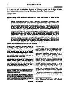
3.1 Experimental set-up and methodology Testbed configuration: Our wireless testbed [16] is deployed in the 3rd floor of Engineering Building II, at the University of California, Riverside. For the purposes of assessing the actual efficiency of MIMO in realistic environments, we utilize a powerful hardware platform. In particular, our testbed consists of 7 Dell PCs with 2.5 GHz dual-core CPU and 1 GB of memory, which run a Debian Linux distribution with kernel v2.6. The node layout is depicted in Figure 1. Each of these devices is equipped with one Ralink RT2860 card that supports MIMO-based (802.11n) communications. Each node carries three 5-dBi onmidirectional antennae, all connected on the RT2860 card. The Linux driver [17] (version 1.6) of the RT2860 can support both STBC and SDM. We have modified the Linux client driver of the RT2860 to enable 2×2 STBC support. This involves adding the line: {"HtStbc",
Set_HtStbc_Proc},
into the RTMP_PRIVATE_SUPPORT_PROC struct array, located in os/linux/sta ioctl.c. The 802.11n (mode 6 in the driver) operates in the 2.4 GHz band; therefore we use this band for all experiments. Note that the latest 802.11n draft standard specifies the WLAN mode only; hence each of our 7 nodes can be set to either Master (AP) or Managed (client) mode. We conducted our measurements when there was no interference from collocated 802.11 WLANs, late at night. Measurement methodology: We perform extensive mea-
3.2.1 Higher throughput with MIMO 2
1
3
6 5 4
7
Figure 1: Our 7-node 802.11n testbed, deployed in the EBU-2 building at UC Riverside. Nodes are represented by diamonds, along with their IDs. surements to characterize the higher layer behavior of 802.11n (MIMO) links in isolation as well as in the presence of other 802.11n and 802.11g (SISO) links. Note that the bit rates that are supported in 802.11n are different from those in 802.11g. Hence, for the experiments that involve similar fixed transmission rates for MIMO and SISO, we try to set rates that are as close as possible. We utilize the iperf measurement tool in all experiments. We inject fully-saturated UDP traffic onto every link; the packet size is 1500 bytes. Each experiment lasts for 30 sec. We provide details on specific measurement procedures later in this section.
3.2 Characterizing MIMO in isolated settings We first examine the possible gains from MIMO when links operate in isolation, i.e., without interference. Our objective is to compare the performance between this case and when operating in multi-access environments. For this, we activate one link at a time. For each link, we first set the two end nodes in 802.11n mode of operation (one as AP and the other as client) and measure the link performance. Subsequently, we set the end nodes of the same link in 802.11g mode and repeat the experiment. We make sure that the experiments for every link are conducted sequentially, one mode after the other, in order to avoid significant changes in the environment. We repeat the 2×30 sec measurements for both MIMO and SISO modes, 20 times. Our main observations are the following: • The throughputs achieved with the MIMO mode are much higher than the corresponding SISO mode (up to 12 times higher). In some scenarios we observed that isolated MIMO links can achieve up to 85 Mbits/sec with STBC! • For a fixed RSSI (Received Signal Strength Indicator) value, the PDR is higher with the MIMO mode of operation. • The number of links in our testbed is much larger with MIMO than with SISO for the same node layout (19% more links with MIMO). • The transmission power required for MIMO in order to achieve the same throughput as that with SISO (on the same link) is much lower; about 50% - 70% lower on average. Below, we deliberate on our experimental findings with regards to the behavior of MIMO in isolation.
As mentioned above, we sequentially activate the links on our testbed and we measure the achieved throughput, first using the MIMO mode and immediately after, with the SISO mode. For these experiments, the default rate control algorithm of the cards was used together with the maximum transmission power (18 dBm). At lower rates, STBC offers higher reliability and therefore provides better performance. Figure 2 depicts the CDF of the throughputs achieved with MIMO and SISO. We observe that MIMO provides tremendous throughput gains! Note also that when the throughput with SISO is low, MIMO boosts the throughput by 10 times or even more. In these cases, the links can support higher transmission rates with MIMO than that with the corresponding SISO. The reason for this improvement is that MIMO improves the reliability of packet transmissions; this in turn reduces the number of packet losses and retransmissions. Figure 3 demonstrates the superiority of MIMO; in this figure we present the corresponding throughputs for the 5 poorest (feasible) SISO links on our testbed when operating on SISO and MIMO mode respectively. Finally, we observe that the use of SDM can provide higher data throughputs; in Figure 4 we present the CDF of the throughputs achieved when SDM mode is used. Note again that, a more extensive study of SDM is beyond the scope of this paper.
3.2.2 MIMO achieves better performance in terms of Packet Delivery Ratio Using the same experimental settings, we measure the PDR (Packet Delivery Ratio) on every link for various RSSI values at the receiver; we vary the transmission powers in order to obtain different RSSI values. For this set of experiments we use fixed transmission rates in order to observe the performance for specific rates. We are mainly interested in high rates where the performance of SISO is expected to present high variations. In Figure 5 we present the results for the scenarios with 54 Mbps with SISO and 60 Mbps with MIMO2 . We observe that the performance benefits with MIMO are significant (as compared with SISO). In particular, the performance of the SISO link is highly unpredictable; high RSSI values do not automatically yield high PDRs on the link. In contrast, the performance of MIMO links is much more stable and predictable, as seen in Figure 5. This is a direct artifact of the higher robustness that MIMO links provide to fading on wireless links.
3.2.3 MIMO improves connectivity We are also interested in examining the percentage of the links on our testbed that are feasible under SISO and MIMO. To accomplish this, we set each node to transmit echo request packets to each of the other 6 nodes and collect the statistics. The maximum transmission power (18 dBm) is used by every node. Upon not receiving echo reply messages, we conclude that the corresponding link is unfeasible, i.e., it cannot sustain data traffic. The results are depicted in Figure 6. We observe that all 21 potential links on our 2 802.11g and 802.11n do not support identical rate specifications.
1
0.6 0.4 SISO MIMO-STBC
0 0
5
3 Link ID
4
0.6 0.4 SISO experiment SISO curve fit MIMO experiment MIMO curve fit −70
RSSI (dBm)
−60
−50
Figure 5: PDR vs RSSI for MIMO and SISO links. For fixed RSSI, PDR is always higher with MIMO.
5
MIMO-SDM 0
80 60 40 20 0 MIMO
SISO
Figure 6: Percentage of feasible links. The number of links with MIMO is much larger.
testbed are feasible with MIMO, whereas 19% of the links are unfeasible with SISO (e.g. links 1↔4, 2↔4, 3↔4 and 1↔7, in the deployment depicted in Figure 1). Note here that our testbed is comprised of 7 nodes only; we expect that in larger scale networks this difference will be much higher. Nevertheless, this set of experiments shows that much denser topologies may be created with MIMO. Again, the results are a direct consequence of the increased reliability with MIMO that is achieved through the use of the STBC mode of operation.
3.2.4 MIMO requires less transmission power than SISO for the same throughput Next, we seek to examine whether the use of MIMO requires less transmission power in order to achieve the same throughput as with SISO. We choose the target throughput to be the maximum sustainable throughput on the considered link (say ξ Mbps). We first set each link to operate in the 802.11g mode and progressively reduce the transmission power (starting at 18 dBm) at both ends until a further reduction in power causes the link to achieve a throughput that is lower than ξ Mbps. The transmission power is noted. Subsequently, we repeat the experiment in the 802.11n mode with the same target throughput. In all cases, the rate adaptation algorithm of our cards was used. Figure 7 presents a representative subset of our results. We observe that MIMO needs only 30-50% of the transmission power that SISO modes need in order to achieve the same throughput! The increased reliability with MIMO could thus be harvested as energy gains. Note also that a MIMO-enabled
20
40
60
80 100 120 140
Throughput (Mbps)
Figure 3: On poor SISO links STBC can boost the achievable throughput. Percentage (%) of total links
0.8
−80
0.4
0 2
100
0.2
0.6
0.2
1
1
PDR
10
0
10 20 30 40 50 60 70 80 90 Throughput (Mbps)
Figure 2: CDF of the link throughput. MIMO achieves higher link throughput in isolation.
0 −90
15
Figure 4: SDM can achieve even higher throughputs as compared to STBC. Percentage of MAX power used
0.2
0.8 Empirical CDF
Throughput (Mbps)
Empirical CDF
0.8
1
SISO MIMO-STBC
20
100 80 60 40 20
SISO MIMO
0 2
4
6
8
10
12
14
16
Link ID
Figure 7: MIMO requires lower transmission power to achieve the same throughput as SISO.
WiFi card may overall expend higher amounts of energy than a SISO card, since the card needs to process all the signals that arrive from the different antennae. Hence, the substantial energy-efficiency benefits that are achieved with a lower transmission power can be potentially handy in a network of mobile devices that are energy-constrained.
3.3 Behavior of MIMO in multi-user settings Next, we examine the behavior of 802.11n links in multiaccess environments, where interference is prominent. While the benefits with MIMO on isolated links are immediate, they are not always feasible in networked settings. In particular, our measurements indicate that: • The 802.11n employs the DCF function as with 802.11g. This does not effectively exploit the capabilities of MIMO. The behavior with MIMO links can significantly suffer when used with coexisting SISO links due to MAC layer effects. • When employed in multi-user scenarios, the use of a wider bandwidth with the channel bonding technique increases the levels of interference imposed from/on the MIMO link. We describe our observations and the interpretations thereof in more detail below. Experimental Settings: We seek to observe the performance of a MIMO link in the presence of other MIMO or
70 60 50 40 30 20 10
70 60 50 40 30 20
SISO
Figure 8: Interaction between a “good” MIMO link and a “good” SISO link.
50 40 30 20
0
0 MIMO
Isolation Competition
60
10
10
0
70
Isolation Competition
80 Throughput (Mbps)
Throughput (Mbps)
90
Isolation Competition
80
Throughput (Mbps)
90
MIMO
SISO
Figure 9: Interaction between a “good” MIMO link and a “bad” SISO link.
SISO links. We examine various pairs of links thereby ensuring that we have a rich set of channel variations between the interfering pairs. First, we activate two interfering links at a time. If the interfering link offers an RSSI that is higher than the CCA (Clear Channel Assessment) threshold [18] on the link under examination, transmissions are precluded on the latter (case a). If not, a transmission is possible but is possibly degraded due to interference (case b). In “case a”, a single link is sufficient to demonstrate the impact of the interfering transmission and thus, our experiments with a single interferer suffice. For “case b”, we also consider multiple such interferers (we call these far interferers). We set the maximum transmission power on all links, while the default rate adaptation algorithm is used by our cards. One of the two links is always in MIMO mode; the other is either a MIMO link or a SISO link depending on the experiment. “Good” SISO links are those links that achieve high throughput in isolation (higher than 20 Mbps); “Bad” SISO links are those that achieve low throughput (lower than 8 Mbps). We consider three representative scenarios that are described below.
3.3.1 Good MIMO links competing Good SISO links We simultaneously activate pairs of MIMO and SISO links that achieve very high throughputs in isolation. Now, we observe that the average throughput achieved on the MIMO link is dropped to approximately 55% of the throughput achieved in isolation (Figure 8). This is a direct artifact of the long term fairness achieved with 802.11. The 802.11n link competes with the 802.11g link and in the long run, is able to access the channel to a similar extent [19]. In other words, only the SISO or the MIMO link can be active at any given time and MIMO capabilities (communications could now be possible even in the presence of interference) are not at all exploited.
3.3.2 Good MIMO links competing Bad SISO links Representative measurement results for this scenario are shown in Figure 9. The performance of the MIMO link is degraded further as compared to the previous scenario. Now, the throughput is approximately 40% of that achieved in isolation. The reason for this is that, the poor quality of the SISO link causes it to operate at low rates. The packets now take longer for transmission and the MIMO link needs to wait in the meantime. Thus, its share of the channel is drastically reduced, causing its performance to degrade.
MIMO
SISO
Figure 10: CSMA/CA degrades the performance for 2 “good” MIMO competing links.
3.3.3 Interactions between pairs of MIMO links A competition between good MIMO links does not lead to a significant degradation in performance; there is approximately, only a 20% throughput degradation (Figure 10). The two MIMO links are able to quickly and efficiently transport their packets (reliable channel due to MIMO) and therefore the hit is not high. Summary: The main reason behind the performance degradation of MIMO in multi-user settings is the CSMA/CA functionality of 802.11n. The 802.11n does not exploit the PHY layer implementation of MIMO to allow multiple, successful concurrent transmissions. Due to this, backward compatibility with legacy 802.11g networks becomes a big issue. Our measurements clearly indicate that MIMO links with very high throughputs in isolation can only achieve much reduced throughputs in hybrid multi-user environments.
3.3.4 Channel bonding increases interference Devices compliant with 802.11n can operate on channels that span either 20 MHz or 40 MHz of bandwidth. In the latter case, channel bonding is used [20]. Channel bonding helps achieve higher data rates (practically doubles the rate). However, when used in a multi-user setting the bandwidth expansion will have side effects in terms of interference. In order to quantify this effect we perform the following set of experiments. a. MIMO vs. SISO on adjacent orthogonal channels. We activate a MIMO link operating on a channel of 20 MHz, i.e. channel X (X ∈ {1, 6, 11}). Simultaneously, we activate a neighbor SISO link (22 MHz) on the adjacent orthogonal channel Y (Y ∈ {1, 6, 11} : |X − Y | = 5); we collect throughput measurements on each link. Subsequently, we change the bandwidth of the MIMO link to 40 MHz and again measure the new throughputs on the two links. The results are plotted in Figure 11. Interestingly we observe that, despite the fact that channel bonding is employed in order to double the transmission rate (and consequently the link throughput), using this technique in a multi-user scenario is actually degrading the throughput! This is because the two previously adjacent orthogonal channels are now overlapping; as a consequence, energy due to transmissions on one channel is spilled into the other channel, thereby causing interference.
802.11n performance with MIMO using 40MHz
802.11n performance with MIMO using 20MHz
802.11n performance with MIMO using 20MHz
802.11g performance with MIMO using 40MHz
802.11g performance with MIMO using 40MHz
802.11g performance with MIMO using 20MHz
802.11g performance with MIMO using 20MHz
Throughput (Mbps)
802.11n performance with MIMO using 40MHz
20 40 Throughput in Mbits/sec
20 40 60 80 Throughput in Mbits/sec
Figure 11: Channel bonding degrades throughput when MIMO links compete with SISO ones on two adjacent orthogonal channels.
Figure 12: Channel bonding does not degrades throughput when MIMO links compete with SISO ones on two nonadjacent orthogonal channels.
c. MIMO vs. MIMO with channel bonding. Next, we consider a scenario with two contending MIMO links that employ channel bonding. As in the above case, the use of adjacent orthogonal channels will lead to performance degradation, as shown in Figure 11. Hence, we are mainly interested in the case where the two links use non adjacent orthogonal channels that span 40 MHz of bandwidth (Figure 12). For this we set one of the MIMO links on channel 1 and the other on channel 11; we activate them simultaneously. Figure 13 depicts a representative time-trace for one of the MIMO links. We observe that the performance of the link is slightly degraded! Note that the central frequencies of channels 1 and 11 are 2.412 MHz and 2.462 MHz respectively, while the bandwidth is 40 MHz, and thus there is no spacing between the two channels. Given that the RF filters of the hardware do not provide sharp cut-offs at the boundaries of the channels, the spectral masks of the signals transmitted in the two channels are partially overlapping [21]; This is the reason for the slight throughput degradation that we observe in Figure 13. In other words, it is extremely difficult (if not impossible) to guarantee complete isolation of two or more simultaneously-active neighbor MIMO links that employ channel bonding, by potentially using a frequency allocation scheme. Our results suggest that channel bonding is a useful technique for increasing the throughput of links operating in isolation. However, one needs to be very careful when adopting this technique in a wide network deployment, due to the aforementioned interference effects.
Isolated link Competing link 0
5
10
15 20 Time(sec)
25
30
Figure 13: Effect of channel bonding on links operating on two non adjacent orthogonal channels, when both links use channel bonding.
two other interferers that can be active at the same time as link 4↔5; the RSSI due to these interferers on the candidate link is lower than the CCA threshold (-80 dBm). The 2 interferers send broadcast messages. We consider both a single and two interferers. We observe in Figure 14 that 802.11n performance degrades much more gracefully due to the far away interferers as compared to 802.11g. In this regime, the benefits due to MIMO are again manifested since the DCF of the 802.11 MAC protocol does not play a role in precluding transmissions when the interferers are active. 90 80 Throughput (Mbps)
b. MIMO vs. SISO on non-adjacent orthogonal channels. We repeat the same experiment on orthogonal channels that are not adjacent. That is, X ∈ {1, 11} and Y ∈ {1, 11} : |X − Y | = 10. We plot the results in Figure 12. We observe that the performance of the links is not affected. This is somewhat expected, since now the two channels are still orthogonal and, as a result, the spectral masks of the transmitted signals do not overlap.
90 80 70 60 50 40 30 20 10 0
70
Isolated 1 interferer 2 interferers
60 50 40 30 20 10 0 SISO
MIMO
Figure 14: Impact of multiple far interferers: 802.11n performance degrades much more gracefully due to the far away interferers.
4. CHOOSING THE RIGHT HARDWARE In this section, we compare different hardware platforms, in order to assess their ability in reproducing our observations. We first provide a brief description of each candidate platform, and subsequently we discuss our comparison.
4.1 The Candidate Platforms We consider three hardware choices: the Soekris net4826, the Soekris net5501 and the Dell 530S desktop PC. Clearly more choices can be considered; we believe that these 3 candidate platforms represent the performance of a much wider pool.
3.3.5 Impact of Multiple Interferers Finally, we examine the impact of multiple distant interferers on 802.11n performance. We use the link 4↔5 as shown in Figure 1 as our candidate link. Through a search, we find
Candidate 1: Soekris net4826. This has been a very popular wireless testbed platform for the past 3 years [22, 16]. It has a 266 MHz i586 processor, an 128 MB of SDRAM
memory, and a soldered compact flash memory. It has been optimized for use as wireless router through the support of two MiniPCI wireless cards. We have extensively used this platform in our testbed for SISO experiments; examples can be found in [18, 23]. Candidate 2: Soekris net5501. The net5501 is a relatively new board, more powerful than the net4826. It contains a 500 MHz CPU and a 512 MB DDR-SDRAM. It can host one MiniPCI and one PCI card. We have drilled the box in order to mount the 3 MIMO antennae that are connected on the RT2860 card. Candidate 3: Dell 530S. This is a powerful PC; it hosts a 2.5 GHz dual-core Intel processor and 1 GB of memory. As with candidate 2, we have drilled the box to mount the 3 antennae. We also use a PCI-to-MiniPCI converter, in order to host the MIMO card (see Figure 15). We perform experiments with transmitter-receiver pairs, using each of the above candidate devices. We follow the methodology that was described in section 3. We would like to point here that other options such as the USRP [11] and WARP [9] boards are possible. However, we have not included measurements with such platforms in this study, since there are no implementations of the 802.11n protocol for these platforms, to date. While such solutions are quite costly, we believe that they can potentially reveal many aspects of the MIMO behavior from the PHY point-of-view, as well as various hidden interdependencies between the PHY and the higher layers.
4.2 Comparing the Platforms Our objective is to select a platform that can reveal the real behavior of MIMO, while addressing the following three objectives: (a) low cost, (b) extendability and (c) re-usability. Throughput. In order to compare the achieved throughput with each of the three platforms, we place a pair of (similar) devices at various locations and we measure the throughput for the following modes of operation: (i) SISO, (ii) MIMO STBC and (iii) MIMO SDM (20 MHz channel). Table 2 presents some representative results for a certain link. We observe that the poor CPU capabilities of the net4826 net5501 Dell
SISO 19.3 23.4 24.1
STBC 33.4 44.2 45.4
SDM 34.1 60.4 62.1
Table 2: Throughputs (Mbps) with various platforms and various modes of operation. net4826 boxes make them inappropriate for MIMO experiments. Their hardware design (weak processor, low memory) cannot perform sufficiently fast packet handling. As a result the end points observe much lower throughputs with MIMO. On the other hand, we notice that the net5501 boxes and the Dell desktops can potentially provide the benefits of MIMO communications. Channel bonding. Channel bonding, as described previously, is expected to (theoretically) provide double the throughput as compared to the default setting of 20 MHz
of channel bandwidth. We provide a comparison of the achievable throughputs with and without channel bonding when using the various candidate platforms. We conduct the same experimental process as in the previous section. The throughput results for the same characteristic link are presented in Table 3. net4826 net5501 Dell
SISO 19.3 23.4 24.1
STBC 20 33.4 44.2 45.4
STBC 40 33.5 83.7 85.9
SDM 20 34.1 60.4 62.1
SDM 40 33.1 118.6 121.2
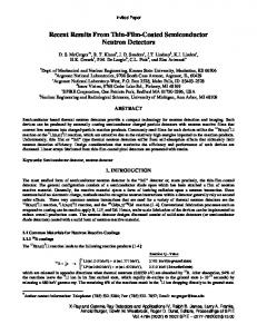
Table 3: Benefits of channel bonding with various platforms (throughput is in Mbps). We observe that the net4826 platform cannot support the true capabilities of MIMO, when channel bonding is enabled. However, the other two platforms are adequate. Connectivity and Energy savings. We conduct experiments with the different hardware choices, to assess their ability in reproducing our findings with regards to the network connectivity (node degree) and the energy savings, as described in section 3. We observe that all three platforms are able to reproduce our connectivity observations. In particular, the observed connectivity among the nodes in the testbed is exactly the same for all three platforms. This is somewhat expected, since connectivity is not related to the processing capabilities of the underlying platform. Finally, we observe that all three platforms are able to reproduce our findings, with regards to the transmission power savings with MIMO while achieving a target SISO throughput. Based on our comparison, we conclude that: (a) Low-CPU devices cannot exploit the tremendous potentials of the MIMO technology. MIMO requires fast packet processing and low hardware implementation overheads. Hence, the net4826 box is not a wise choice for MIMO experiments. (b) Since we prefer an affordable, extendable device, the most wise choice is a powerful desktop PC, such as our candidate Dell machine. Although its cost is similar to the net5501, the latter does not offer re-usability. As an example, due to its 500 MHz CPU, it cannot efficiently host USRP devices [11], which require at least 1 GHz server processors. Other, less affordable devices with more advanced capabilities could also be adequate (such as the ORBIT hardware [24]). Our testbed set-up. The core design of our testbed is described in [16]. Each node in the testbed is represented by a set of devices, which are connected as shown in Figure 16. In particular, device sets are interconnected through a PoE switch, while provides power to the Soekris boards. Moreover, a local switch in every set connects the Soekris board with the Dell machine. The latter carries the RT2860 card. It also hosts a USRP and a WARP device. In other words, the Dell machine works as a local server for these two devices. Note here that we are able to remotely power on/off the Soekris box by means of our PoE switch and a PoE splitter. Even when the power is off at the PoE port of the central switch, communications with the rest of the devices in the set, remain unaffected.
5. DISCUSSION AND CONCLUSIONS We perform a measurement study in order to understand the inherent properties of MIMO in real deployments. Our
SERVER PoE SWITCH SPLITTER
SWITCH
RT-MIMO
WARP SOEKRIS
USRP Device Set
Figure 15: Our selected platform for performing MIMO experiments. It carries a MIMO-enabled WiFi card, while it hosts a USRP and a WARP board.
Figure 16: The hardware connectivity in our testbed. Each node is represented by a device set of locally interconnected platforms. The device set is connected through a PoE splitter with the other sets.
measurements validate that the performance of an isolated 802.11n (MIMO) link provides significant benefits as compared to conventional 802.11g (SISO) systems. The performance of the same link can be significantly lowered in a networked setting. In particular, coexisting 802.11g links can be pernicious to 802.11n performance. The main reason for this degradation is the DCF function in the 802.11 MAC standard (the same in both 802.11n and 802.11g). We use our experimental observations to test the appropriateness of different hardware platforms that a network architect may choose for deploying a MIMO network. We observe that the CPU processing capabilities play a dramatic role in being able to exploit the performance benefits of the MIMO technology. Given this observation, we suggest the most appropriate hardware platform, taking into consideration the financial cost, the re-usability and the extendability of the device. We believe that our study can be a blueprint for future efforts towards designing and deploying efficient, affordable MIMO testbeds.
6.
REFERENCES
[1] H. Jafarkhani. Space-Time Coding: Theory and Practice. Cambridge University Press, 2005. [2] P. Goud Jr, R. Hang, D. Truhachen, and C. Schlegel. A Portable MIMO Testbed and Selected Channel Measurements. In EURASIP Journal of Applied Signal Processing, 2006. [3] C. Mehlfuhrer, S. Geirhofer, S. Caban, and M. Rupp. A Flexible MIMO Testbed wit Remote Access. In EURASIP Journal of Applied Signal Processing, 2005. [4] D. Kim and M. Torlak. Rapid prototyping of a cost effective and flexible 4x4 mimo testbed. In 5th IEEE Sensor Array and Multichannel Signal Processing Workshop, 2008. [5] MASCOT:Multiple-Access Space-Time Coding Testbed. http://www.ist-mascot.org/. [6] H. Van and Dyke Parunak. MASCOT: A Virtual Factory for Research and Development in Manufacturing Scheduling and Control. In 3rd Workshop on Intelligent Scheduling in Manufacturing, 1993. [7] S.M. Alamouti. A simple transmit diversity technique for wireless communications. In IEEE Journal on Selected Areas in Communications, October 1998. [8] J.-C. Belfiore, G. Rekaya, and E. Viterbo. The Golden
[9] [10]
[11] [12] [13]
[14] [15] [16] [17]
[18]
[19]
[20]
[21]
[22] [23]
[24]
Code: A 2 x 2 Full-Rate Space-Time Code with Non-Vanishing Determinants. In IEEE Transactions on Information Theory,, April 2005. WARP: Wireless Open Access Research Platform. http://warp.rice.edu/trac. J. Camp and E. Knightly. Modulation Rate Adaptation in Urban and Vehicular Environments: Cross-layer Implementation and Experimental Evaluation. In ACM MOBICOM, 2008. GNU Radio - The GNU Software Radio. http://www.gnu.org/software/gnuradio/. Ettus Research LLC. http://www.ettus.com/. G. Daniels H. Suzuki, M. Hedley and J. Yuan. Performance of MIMO -OFDM-BICM on Measured Indoor Channels. In IEEE VTC, Spring 2006. Ralink: MIMO technology. http://www.ralinktech.com. ANSI/IEEE 802.11-Standard. 1999 edition. UCR Wireless Testbed. http://networks.cs.ucr.edu/testbed. RT2860 wireless driver. http://www.ralinktech.com/ralink/Home /Support/Linux.html. I. Broustis, K. Papagiannaki, S. V. Krishnamurthy, M. Faloutsos, and V. Mhatre. MDG: Measurement-Driven Guidelines for 802.11 WLAN Design. In ACM MOBICOM, 2007. M.Heusse, F.Rousseau, G.Berger-Sabbatel, and A.Duda. Performance anomaly of 802.11b. In INFOCOM, 2003. B. O’hara and A. Petrick. IEEE 802.11 Handbook, a Designer’s Companion. IEEE Press, Second Edition, ISBN 0-73-814449-5. J. Yee and H. P-Esfahani. Understanding Wireless LAN Performance Tradeoffs. In http://www.commsdesign.com, 2002. Soekris Engineering. http://www.soekris.com. G. Jakllari, S. Eidenbenz, N. Hengartner, S. V. Krishnamurthy, and M. Faloutsos. Link Positions Matter: A Noncommutative Routing Metric for Wireless Mesh Networks. In IEEE INFOCOM, 2008. ORBIT, WinLab. http://www.orbit-lab.org.