Scalability Considerations and Evaluation for Distributed Mission Training Systems Hessam S. Sarjoughian Bernard P. Zeigler Xiaolin Hu Arizona Center for Integrative Modeling & Simulation University of Arizona, Tucson, Arizona Email: {hessam|zeigler|Hu}@ece.arizona.edu URL: www.acims.arizona.edu
Robert A. Strini
Daryl R. Hild
Emerging Business Solutions, Smithfield, Virginia Email:
[email protected]
MITRE Corporation, Sierra Vista, Arizona Email:
[email protected]
Keywords: Architecture, Co-Design, C2I, DEVS, Distributed Object Computing, DMT, JSAF, Methodology, Scalability
Abstract: Distributed Mission Training is a promising technology in support of training in general and within DoD in particular. Architectural considerations (interplay of hardware and software) is instrumental given high demands for network bandwidth and computing resources in relation to proliferating software complexity. This paper proposes a co-design modeling and simulation methodology and environment (Discrete Event System Specification/Distributed Object Computing) founded on the principles of concurrent software and hardware analysis and design. The methodology is exemplified via a prototype distributed Mission Training and Rehearsal System. The architecture of the prototype is discussed along with the simulation results depicting the prototype’s scalability given alternative configurations.
1
Introduction
Distributed simulation training systems have achieved various levels of success replicating battlefield conditions for the warfighter. The limitations that exist are often the result of inadequately designed training systems that do not consider or contain the ability for various input/output requirements of the warfighter. Within the Command and Control (C2) environment, this limitation is exaggerated due to the complexity of the various systems that support joint mission execution. Participating in this joint C2 mission is the USAF Ground Theater Air Control System (GTACS) which does not train today as a complete weapons system due to the limitations of a non-existent Distributed Mission Training (DMT) environment [1]. A potential solution was developed to meet this need and is the object of this evaluation. The Mission Training and Rehearsal System (MTRS) prototype demonstrated an initial proof-of-concept for a comprehensive training system to support Air Force Command and Control (C2) training. MTRS aim is to support academic learning, proficiency training and mission rehearsal through standalone and distributed methods. The payoff to the warfighter will be the ability to conduct various phases of mission execution within one training system on demand
and with minimal Human-in-the-Loop coordination at an acceptable level of resolution. The prototype includes a distributed simulation system with computer generated forces, terrain, environment and cognitive agents such as pilots, to replace today’s human support role players. The combat scenarios developed for this prototype provided training opportunities for four elements of the Ground Theater Air Control System (GTACS): Control and Reporting Center (CRC), Aerospace Operations Center (AOC), Air Support Operations Center (ASOC) and the Tactical Air Control Party (TACP). A single operator duty position for each element was designed to receive training through webbased courseware, practice sessions and distributed simulation mission sessions. Funding cutbacks reduced the AOC and ASOC positions to a role player observing the key elements of information necessary for the operator to execute mission processes. The two primary duty positions were the CRC Weapons Director (WD) and TACP Enlisted Terminal Attack Controller (ETAC). Differences in mission accomplishment by GTACS operators and individual pilot training are noteworthy in several ways. Initially, GTACS operator’s skill or positional training requires small-scale forces and scenario elements. As exercise level’s progress toward team or crew training, MTRS must support the ability to
1
scale the conflict towards a Major Regional Conflict (MRC) or Major Theater War (MTW). Operationally, this means the training system must be able to include many tactical missions, Rules of Engagements (ROE), Special Instructions (SPINS) and pre-mission planning considerations to handle the enormous number of combat situations that could arise. It is the responsibility of the training provider to determine how valid the training environment can support this requirement. Typically, human instructors maintain the realism factor by inserting expertise when the system cannot meet realistic demands. MTRS includes the use of intelligent tutors and a Computer Managed Instruction to support time management responsibilities of the limited human instructors. This element of support adds to the challenge of distribution responsibilities and is a factor in the evaluation of the MTRS architecture. The wide range of capabilities to be offered by MTRS demands an architecture that is scaleable, while supporting heterogeneity, openness, resource sharing, and fault-tolerance. Such considerations (captured as HLA management services) are essential in building HLAcompliant simulation models. Specifically, this study is to evaluate expected increased bandwidth requirements of successively larger organizations and the capabilities of projected network infrastructures based on candidate network infrastructures and hardware platforms. The objective of modeling MTRS architecture is to be able to predict the scalability of the developed prototype from a few trainees to larger command structure organizations in real time using HLA-compliant simulations. For example, initially, MTRS is to be used by a small number of interacting participants (eight or less) at multiple sites. The end-state vision of MTRS is to provide many users at many sites the ability to conduct a MRC or MTW.
2
focus in this report is on MTRS, the approach is applicable to distributed systems such as those required to meet other DMT requirements. The approach relies on an iterative process through which the accuracy of models is incrementally improved. This makes it possible to gain confidence that the overall MTRS model is valid at an adequate level of resolution. The model can then be extended and simulated to predict alternative, “scaled up” versions of MTRS without actually building them. 2.1
THE DEVS/DOC MODELING AND SIMULATION ENVIRONMENT M&S has become increasingly the most suitable vehicle to study the complexities associated with the development of distributed object computing systems such as Distributed Mission Training systems. The Discrete-event System Specification (DEVS) modeling and simulation framework supports modular, hierarchical representation of components of such systems [4]. With it, we can model hardware and software components (e.g., processors, networking topologies, communication protocols, software objects) of a distributed system with varying degrees of resolutions and complexities in a systematic and scaleable manner. The ability to evaluate architectural attributes (e.g., scalability) of distributed systems using dynamic models is invaluable to designers, developers, and decisionmakers. Within the DEVS/DOC modeling and simulation environment, important components of advanced systems such as MTRS can be represented and simulated to include the complex interactions occurring among hardware and software components. Furthermore, alternative design choices and tradeoffs among them can be studied. For example, a proposed MTRS architecture can be simulated to decide how well it scales as the number of its concurrent users increases.
Approach
The approach undertaken for evaluation of the MTRS is based on a modeling and simulation methodology called DEVS/DOC (Discrete Event System System/Distributed Object Computing) [2, 3]. This recently developed methodology provides a generic framework to model and simulate hardware and software components of distributed systems such as DMT networked systems. An essential part of this approach is based on the validation of model components and their integration against their real-world counterparts. Hardware components of MTRS (e.g., computers and network) are modeled based on manufactures’ specifications. Software components are modeled based on suitable abstractions of their execution behaviors. The general strategy is to model various capabilities of MTRS (and its future incarnations) and then validate the model against measurements made on the actual prototype. It should be noted that while our
Design choices to achieve scalability are available at the hardware and software levels. For example, from the hardware point of view, a processor’s speed, buffer size, and a network’s bandwidth are key design parameters. Similarly, from software point of view, the choice of data communication protocols, objects' multi-threading capabilities and memory requirements are important design considerations. These software/hardware design choices combine in complex ways so as to make the development of distributed systems such as MTRS very challenging. Complexities in the behavior and performance of such systems arise from two sources: 1) the intricacies of individual components (both software and hardware), and 2) more importantly, the numerous interactions of hundreds of components dispersed across a network. Without modeling and simulation tools at hand, these complexities make it difficult to know how to distribute software components across a network in order
2
to appropriately match software computational needs against hardware resources. And, without proper distribution of software components, we are likely to
greatly overestimate the bandwidth and processing requirements of the underlying hardware, resulting in greater costs for less performance.
Microphone
CourseBuilder
HTML events
User Interface
Client Application (VNC Client)
(MTRE)
iGEN
Database CMI
MTRS Trainee/Supervisor
Speaker
AAR
MTRS
Database Software Component Soar Speak/Generator (Via Voice)
Data Flow Control flow Databases
SAF
SOAR
JSAF Federation
Events to socket
Server Application (VNC Server)
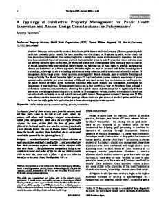
Expected heavy data traffic MTRE: Mission Training & Rehearsal Executive
Figure 1: MTRS architecture
MTRS (Software Components)
MTRS (Hardware Components)
Browser, VNC Client Courseware SoarSpeak/SoarGen Database, Computer Managed Instruction JSAF, Soar, VNC Server IGEN
DEVS/DOC Components (Simulation Model) WD: (Weapon Director) CW: Courseware SS: SoarSpeak DB: Database
Ethernet Computer (Win. 98) Computer (Win. NT) Computer (Linux)
JSAF: Joint SAF iGEN: AI Tutor Ether1 PC1 PC2 PC3
Table 1: MTRS hardware/Software components and their corresponding DEVS/DOC simulation models
3
MTRS Architecture
A simplified software component architecture of MTRS is shown in Figure 1. The Browser, Courseware, SoarSpeak, SoarGen, Database (Computer Managed Instruction),
JSAF, and AI-tutor (iGEN) constitute the major software components of MTRS. Data and control communication/interactions can take place among these components. Specifically, we will evaluate the increasing bandwidth requirements of successively larger
3
organizations and the capabilities of projected network infrastructures to support these requirements based on candidate network infrastructures (e.g., LAN vs. WAN) and hardware platforms. Table 1 shows MTRS components and their counterpart DEVS/DOC simulation models assuming three computers and a local area network. The table as shown includes all major software and hardware components of MTRS. The DEVS/DOC simulation models represent either distinctly or as an aggregate, the MTRS prototype. Consider the Virtual Network Computing (VNC) server and client applications. In the current realization and operation of MTRS, VNC client and server are distinct software applications. However, in the MTRS model they are aggregated as part of JSAF and WD simulation models.
4
MTRS DEVS/DOC Simulation Models
The system modeling effort for distributed systems such as MTRS can be managed in four steps. First, the network (processing nodes, gates, and links) is defined. Second, the software objects and their interaction with one another are defined. Third, software objects are mapped onto the processing nodes and interactions between software components and their links. Fourth, a set of experiments to simulate the model and to collect pertinent data for functional and behavioral analysis is defined. The products for steps 1-3 are a Loosely Coupled Network
(LCN), a set of Distributed Cooperative Objects (DCO), and an Object System Mapping (OSM), respectively [5]. The software components of browser (the interface to the trainee), courseware, SoarSpeak/SoarGen, iGEN, database, and JSAF are modeled individually (see Figure 2). Each model is specified in terms of operations (methods) it can perform and memory size required for an executing software application. Two essential elements of any software object model are attributes and methods. The methods of software applications are specified in terms of their data size and resources required for processing. For example, an executing JSAF application typically requires 256MB of RAM. Messages produced by JSAF have an average size of 1500 bytes and messages received by JSAF have an average size of 100 bytes (see MTRS Measurements subsection for further explanation). We note that while MTRS model is based on the MTRS prototype, it does not match it exactly in terms of LCN, DCO, and OSM. Nevertheless, we believe MTRS model captures essential characteristics of the MTRS actual realization. Similar to software components, hardware components exhibit dynamic behavior and therefore must be modeled (see Figure 2). Compared to software components, hardware components can be simpler to model and easier to customize. For MTRS, existing processors, hubs, and Ethernet models per specification of their real-world components were customized.
Network Traffic
VNC client
VNC server
Database
JSAF
Courseware Web Browser Software Applications (SA) SoarSpeak
PC (Windows 98 OS)
iGEN SA
Web Server Software Application
PC (Windows NT OS)
PC (Linux OS)
Weapon Director LAN
Figure 2: Simulation models of the MTRS
4
load transmitted. Similarly, transducers for processors reveal the amount of work each has performed during a simulation run. JSAF simulation model transducer measures number of messages received/invoked and workload (CPU processing cycles) allocated to it by its corresponding processor.
In order to evaluate MTRS model, a defined set of transducers to measure metrics of interest are listed in Table 2 [2]. Individual transducers (simulation models) are defined for all hardware and software simulation models. For example, with the transducer defined for the Ethernet, we measure metrics such as number of collisions, successful number of transmissions, and data
LCN Classes Description of Metric
Processor
Computational Work Performed Active Time/Utilization
Gate
DCO Classes Link
Domain
Object
∗
∑
∗
∗
∗
∗
I/O Data Load
∗
∑
∗
Utilization of Storage
∗
Percentage of Active Objects
∗
Degree of Multithreading
∗
Interaction Arc
∗ ∗ ∗
Length of Execution Queues # of Initialization Invocations
∗
∗
Total Execution Time
∗
∗
Coefficient of Interaction
∗
Data Traffic
∗
∑
Utilization of Bandwidth
∗
∑
∗
∑
∗
∗
∑
∗
∗
∑
∗
% of Packet Retransmission Length of Packet Buffer
∗
Net Throughput of Data Rate of Overhead
∗
Gross & Net Response Time
Table 2: Major DOC system simulation metrics
4.1 MTRS Measurements All MTRS models need to be verified and validated individually and in joint operation. Of particular importance is verification and validation of software components. The verification and validation of these models require measurements both in isolation and within the overall operation of MTRS. A series of measurements for JSAF and the database (MS Access database) were conducted under nominal conditions to measure their essential parameters (i.e., memory usage and CPU resource utilization). Some software applications (courseware and SoarSpeak/SoarGen) were not available for measurements and some others could not lend themselves for standalone measurements. However, we have characterized such software applications by gathering relevant knowledge from their developers. Aside from standalone testing, a set of measurements was obtained for the MTRS under the 1v1 scenario. These
measurements provide messages exchanged among software applications. Specifically, measurements were obtained in terms of frequency of messages sent from one software application to another, size of messages, and their transmission times. Thus, both component wise and system measurements have been used to verify and validate MTRS DEVS/DOC models individually and collectively to the extent possible (see Figure 4). 4.2 Scaling MTRS Architecture To study the scalability of MTRS, we have chosen a typical three-tier architecture. This architecture is composed of two computing nodes. One node executes VNC, JSAF, and Webserver software objects and another executing Database and iGEN software objects). Each client node (Trainee) executes SoarSpeak, Webrower, Courseware, and VNC client software objects. In this architecture, the number of clients can be increased from 1 to n assuming a single JSAF, iGEN, and database. The simulation of MTRS model reveals the impact of
5
900 800 Packet Size (bytes)
700 600 500 400
Series1
300 200
196
181
166
151
136
121
91
106
76
61
46
31
1
100 0 16
increased clients’ demand on resources such as database, iGEN, and JSAF. The MTRS architecture can be varied to examine other alternatives in terms of hardware configurations (e.g., changing Ethernet speed from 100 mbps to 100 kbps). In accordance to alternative architectures, the number of hardware and software components is increased to examine their scalability traits. For example, LCN simulation models are modified. Similarly, DCO simulation models and their interactions are revised.
Packet Num
120
(a) Messages sent from JSAF to iGEN (Average 364 bytes)
Aug 29, 2000
100 80 Series1 Series2
60
Series3
34
31
28
25
22
19
1
(a) CPU Utilization
Series1
16
23 45 67 89 111 133 155 177 199 221 243 265 287 309 331 353
13
1
10
0
7
Packet Size (bytes)
20
200 180 160 140 120 100 80 60 40 20 0 4
40
Packet Num
(b) Messages sent from SoarSpeak to JSAF (Average 124 bytes)
80 Aug 29, 2000
70 60 50
Series1
Figure 4: Message exchanged among JSAF, SoarSpeak, and iGEN
Series2
40
Series3 Series4
30 20 10 0 1
23 45 67 89 111 133 155 177 199 221 243 265 287 309 331 353
(b) Memory Usage
Figure 3: Memory and CPU usage for JSAF
4.3 Simulation Results In this section, we discuss simulation results depicting the scalability of the MTRS architecture. Specifically, we discuss the viability of scaled MTRS architecture in terms of its performance (e.g., network traffic, bandwidth effects, computational loads, etc.). Furthermore, we determine whether the system’s behavior can remain correct. We predict under what conditions the system will fail to operate correctly (e.g., due to insufficient memory or excessive message latency, software objects fail to send/receive messages from one another. The following figures illustrate simulation results obtained for MTRS using the 3-tier architecture. Figure 6 (a), (b), and (c) show the how increasing number of trainees (i.e., Weapon Directors (WD) and SoarSpeak (SS)) from 1 to 40 affects Ethernet data throughput, response time for invoked messages, and job throughput for the machine hosting JSAF. The measurements in Figures 6 are based on 10 multiple independent
6
simulation runs to account for randomness present in the DEVS/DOC models. These measurements are based on the followings:
actual measurements obtained from MTRS and its components. Examination of Figure 6 shows that with the scaled 3-tier architecture assumed for MTRS will begin to experience delays (see Figure 6(b)) as the number of trainees increases. Assuming 10 mbps Ethernet speed, 20 trainees accessing one JSAF computer supporting multiple simulation scenarios experience small delays of up to 0.059 seconds. The delay, however, becomes significant (0.269) assuming 1 mbps Ethernet speed.
LAN (TCP/IP Ethernet) Speed: 1-10 mbps Number of Segments: 5 Maximum Packet Size: 1500 Bytes CPUa (responsible for JSAF) CPU Speed: 800 MHz Memory: 512 MB CPUb (responsible for database and iGEN) CPU Speed: 600 MHz Memory: 256 MB CPU1,…,40 (each processor is responsible for browser, courseware, and SoarSpeak/SoarGen) CPU Speed: 400 MHz Memory: 128 MB
Due to limited space, only a few basic specifications for hardware components were included. No specifications for software components were included. Hardware and software simulation models have been designed based on
The MTRS architecture can support many to many JSAF back-end to front-end clients and thus can reduce undesirable delays due to CPU loading. It should be noted that although MTRS system responsiveness degrades significantly (sees Figure 6(b)), its behavior remains correct. The correct behavior is evident since the number of messages and amount data exchanged among software objects is proportional to scaled variations of MTRS. The behaviors of the alternative simulation models only differ in terms of their duration.
Data Throughput (bits/sec)
Ethernet Data Throughput 410000 408000 406000 404000 402000 400000 398000 396000 394000
10 mbps
0
10
20
30
40
50
Number of Trainees
Ethernet Data Throughput
Data Throughput (bits/sec)
4000000 3900000 3800000 1 mbps 3700000 3600000 3500000 0
10
20
30
40
50
Number of Trainees
(a) Ethernet data throughput
7
Response Time (sec)
Weapon Director Response Time 0.2 0.15 10 mbps
0.1 0.05 0 0
10
20
30
40
50
Number of Trainees
Response Time (sec)
Weapon Director Response Time 2 1.5 1 mbps
1 0.5 0 0
10
20
30
40
50
Number of Trainees
(b) Invocation message response time for Weapon Director (seconds)
Job Throughput (jobs/sec)
Job Throughput (PC Hosting JSAF) 250 200 150 10 mbps
100 50 0 0
10
20
30
40
50
Number of Trainees
Job Throughput (jobs/sec)
Job Throughput (PC Hosting JSAF) 35 30 25 20 15 10 5 0
1 m bps
0
10
20
30
40
50
Number of Trainees
(c) Job throughput for PC hosting JSAF
Figure 5: Measurements for 1 to 40 MTRS trainees on LAN Since bandwidth related constraints (Ethernet and NIC specification) are known to affect the behavior of distributed systems, we can evaluate the impact of alternative Ethernet and Network Interface Card (NIC)
configurations. We have, therefore, conducted 5 simulation runs according to Table 3, where decreasing capability of successive configurations is evident. In all simulation runs, the number of trainees is set to 5. To
8
account for randomness incorporated in the MTRS models, each scenario was repeated 10 times. The simulation results suggest that while it is possible to reduce the quality of Ethernet and NIC, there exist a breakpoint at which the system will not behave correctly. An examination of Figure 6 reveals that the number of messages drops from 330 to 24 depending on the configuration. While the MTRS architecture can maintain its correct behavior for scenarios I and II, the remaining scenarios show that fewer messages are produced by software objects and thus sent to others. Consider scenario III. In this scenario, the configuration of Ethernet
and NIC are responsible for messages not reaching their destinations and thus resulting in incorrect behavior. The source of system failure can be attributed to limited number of times a message can be sent across the network. After a finite number of attempts, messages will not be sent out which then results in intended software objects not receiving them. For example, in scenario III, IV, and IV, JSAF cannot receive all messages invoked by SoarSpeak. Unfortunately, in complex systems such as MTRS, lack of successful message transmission between two software objects results in cascading failures throughout the system.
Configuration
NIC Speed (bits/sec)
NIC Bandwidth (bits/sec)
Ethernet Speed (bits/sec)
1
1E8 (100 mbps)
1E7 (10 mbps)
1E6 (1 mbps)
2
1E7 (10 mbps)
1E6 (1 mbps)
1E5 (100 kbps)
3
1E6 (1 mbps)
1E5 (100 kbps)
1E4 (10 kbps)
4
5E5 (500 kbps)
5E4 (50 kbps)
5E3 (5 kbps)
5
1E5 (100 kbps)
1E4 (10 kbps)
1E3 (1 kbps)
Table 3: Ethernet and NIC alternative configurations
Successful Transmissions
Transmissions 350 300 250 200
Transmissions
150 100 50 0 0
1
2
3
4
5
6
Ethernet/NIC Alternative Configurations
(a) Successful transmissions Collisions
Number of Collisions
12 10 8 6
Collisions
4 2 0 0
1
2
3
4
5
6
Ethernet/NIC Alternative Configurations
(a) Number of collisions across Ethernet Figure 6: Ethernet successful transmissions and number of collisions
9
5
Related Work
Development of Distributed Mission Training systems is increasingly based on the HLA/RTI framework. An example of such an effort is the Joint Theater Level Simulation (JTLS) with reported improved capabilities [6]. While HLA/RTI framework is capable of supporting design of such distributed wargaming environments (e.g., JTLS-NATO and JTLS-EADSIM federations), it has not been devised to support explicitly combined hardware and software (co-design) architectural requirements. Analysis studies (see [7]) have been used to examine the applicability of HLA/RTI to high-fidelity distributed mission training. Such studies reveals important implementation related issues (e.g., alternative RTI implementations in order to evaluate performance metrics such as RTI data throughput and time synchronization) in contrast to the architectural issues. Another analysis study which is more closely related to ours considered the distributed C-5 Weapon System Trainer [8] in terms of network bandwidth utilization and RTI latency among others. The aim of the study was to determine the number of entities that can be supported. The analysis (testing) measured network bandwidth, CPU utilization, transport delay, and behavioral correctness (entity displacement inaccuracies between the true position computed by one simulator and its corresponding dead-reckoned position by another). Such measures showed, for example, that the distributed C-5 Weapon System Trainer could support a few 10’s of entities. Based on extrapolated simulated network bandwidth, it was predicted that some two hundred entities could be executed on a T-1 line with no voice channel. Another analysis showed that slow CPU speed could become the limiting factor scaling to hundreds of entities as opposed to the network bandwidth. Our approach, in contrast, enables model-based scalability predictions based on bandwidth, memory, CPU speed, computational workload, etc. using meta-simulation.
6
Summary and Future Research
In this study, we have examined architectural and scalability aspects of MTRS and Distributed Mission Training Systems in general using the proposed DEVS/DOC co-design methodology. Simulation models of the MTRS were devised based on architectural prerequisites and the interplay among its software and hardware components. The simulation results indicate how revealing concurrent hardware and software analysis and design can be – despite not having all models validated against their actual realizations. For example, up to 10 trainees per site can be accommodated for the nominal configuration based on MTRS hardware and software nominal specification (see Section 4.3). Using
the co-design methodology, the performance of MTRS can be improved by adopting an architecture accommodating a large number of users dispersed geographically while maintaining high fidelity simulation, voice recognition and synthesis, and AI-Tutor capability. For example, to reduce the number of messages and the data transmitted between simulation nodes of JSAF, techniques such as HLA’s Data Distribution Management [9] and quantization-based filtering [10] may be employed. Use of these and other techniques within a well-defined methodology can significantly advance the performance DMT systems. Furthermore, it suggests use of co-design for distributed simulation within the Simulation-Based Acquisition. 6.1 Acknowledgements We are thankful to the MTRS team and in particular to Derek Bryan (BMH), Paul Nielsen (Soar Technology, Inc.), Thomas Richards (Langley AFB), Keith Strini (Emerging Business Solutions), and Wayne Zachery (CHI Systems, Inc). This study was supported by Langley AFB, under Contract Number 1435-01-00-CT-31045.
References 1.
Strini, B., Airpower and Simulation Assessment of Ground Theater Air Control System Training, 1999, Emerging Business Solutions: Smithfield, Virginia. 2. Hild, D.R., Discrete Event System Specification (DEVS) Distributed Object Computing (DOC) Modeling and Simulation, 2000, University of Arizona: Tucson, AZ. 3. Sarjoughian, H.S., D.R. Hild, et al, DEVS-DOC: A CoDesign Modeling and Simulation Environment, IEEE Computer, 2000, 33(3): p. 110-113. 4. Zeigler, B.P., H. Praehofer, and T.G. Kim, Theory of Modeling and Simulation, Second Edition, 2000, Academic Press. 5. Butler, J.M. Quantum Modeling of Distributed Object Computing, in 28th Annual Simulation Symposium. 1995, IEEE Computer Society Press. 6. Prochnow, D.L., C.Z. Furness, et al, The Use of the Joint Theater Level Simulation (JTLS) with the High Level Architecture (HLA) to Produce Distributed Training Environment, in Simulation Interpretability Workshop, 00F-SIW-079, 2000, Orlando, FL. 7. Mealy, G.L., et al, Analysis of the Applicability of HLA/RTI to Distributed Mission Training, in Simulation Interpretability Workshop, 99S-SIW-083, 1999, Orlando, FL. 8. Murray, B. and S. Monson, Analysis of a Real-Time HLA Distributed Mission Training Federation, in Simulation Interpretability Workshop, 00S-SIW-045, 2000, Orlando, FL. 9. HLA, High Level Architecture, 1999, Defense Modeling and Simulation Office: http://hla.dmso.mil. 10. Zeigler, B.P., et al, Bandwidth Utilization/Fidelity Tradeoffs in Predictive Filtering, in Simulation Interpretability Workshop, 99S-SIW-063, 1999, Orlando.
10
11