Jul 2, 2016 - The pulse tone generator generates a square or rectangular wave of good audio up to 32dB. By application of a pulse width modulated signal ...
International Journal of Innovation and Scientific Research ISSN 2351-8014 Vol. 25 No. 2 Jul. 2016, pp. 405-412 © 2015 Innovative Space of Scientific Research Journals http://www.ijisr.issr-journals.org/
Design and Implementation of a Variable Pulse Tone Generator Based Alarm System for Emergency Signaling Ehiagwina Ojiemhende Frederick, Kehinde Oluseye Olufemi, Seluwa Emmanuel Oludare, Afolabi Lateef Olashile, and Yakub Bolaji Jamiu Department of Electrical Electronics Engineering, Federal polytechnics Offa, Offa Kwara state, Nigeria
Copyright © 2016 ISSR Journals. This is an open access article distributed under the Creative Commons Attribution License, which permits unrestricted use, distribution, and reproduction in any medium, provided the original work is properly cited.
ABSTRACT: The pulse tone generator provides one with the application of two 555 timers, resistors, electrolytic capacitors and a power source, all being connected together on a Vero board. This project attempted to incorporate into previously developed pulse tone generator useful features such as making the circuit simpler, variation to the tone by means of a variable resistor knob. A polyvinyl chloride (PVC) case is used as against metallic casings used in some previous works. In this project, a regulated dc power supply starting with a 220/12 volt, 500VA step down transformer is used to power the circuit. When the circuit is connected to the power source, the 555 timer IC triggers the loudspeaker to emit a loud audible sound. This sound will stay on for as long as the circuit is connected to the dc power supply. The component and circuits was tested and the design was implemented and realized.
KEYWORDS: 555 timer, alarm system, emergency signaling, multivibrator, and pulse tone generator. 1
INTRODUCTION
Pulse tone generator provides the base circuit in the construction a simple alarm system that can be placed on appropriate location such as the door of a house [1]. It can be used as a burglar alarm or emergency alert system. The system is portable and flexible. Also, the pulse tone based alarm system for emergency alert system can be placed in a vehicle, which can be switched ON in an emergency to emit sounds that can frightens an intruder [2]. The pulse tone generator is used in telephone number dial-tone system. The triggering circuits can easily be adapted to trigger type of stimulus sources other than tone pulses such as: flashes, stimuli, etc. for different kinds of psyco-psychological experiments [3]. The pulse tone generator generates a square or rectangular wave of good audio up to 32dB. By application of a pulse width modulated signal to a tuned resonant circuit having a loudspeaker, one is able to reproduce a wide variety of quality tones [4]. The waveforms generated by the pulse tone generator are either astable or monostable or bistable. However, pulse tone generator based alarm system for emergency signaling is yet to be fully localized and exploited within Nigeria. This project uses two 555 timer ICs, a loudspeaker, resistors, electrolytic capacitors, diodes and a step down transformer in the implementation of the system [1]. When the circuit is connected to 12 V power supply, the alarm will trigger at a frequency of approximately 1.27 KHz, and it will stay ON until the power source is removed. The aim of this project is to design and implement a pulse tone generator based alarm system for emergency signaling, with the following objectives: • • • •
Design and plotting of the electronic components Preconstruction of the components on the bread board Implementation of the circuit on a vero board Testing and packaging of the implemented circuit
Corresponding Author: Ehiagwina Ojiemhende Frederick
405
Design and Implementation of a Variable Pulse Tone Generator Based Alarm System for Emergency Signaling
2 2.1
LITERATURE REVIEW AND COMPONENTS DESCRIPTION 555 TIMER IC AND ITS OPERATION
The 555 timer is an integrated circuit used in several timer circuit such as pulse generation and oscillator applications. When the voltage at a pin 2 (the trigger) falls below 1/3 of the supply Vcc (brief connecting it to the ground). The IC is triggered and the output (pin3) rises to near Vcc, grounding pin 2 and also switches off the transistor grounding pin 7 and this allows its voltage to rise. The capacitor, which is connected between the Pin and the ground, starts to charge pin 6, and when its voltage reaches 2/3 of Vcc, it switched on the transistor causing pin 7 to return to ground again. The capacitor is discharged and will remain so until pin 2 is again triggered. Pin 4 is used to reset the IC i.e. it causes the output to return to zero volt if it is connected to zero volt (0V) the control (2/3Vcc) is brought out to pin 5 and therefore allows for a different control voltage to applied or for it to be completed decoupled to make the device more immune to noise (Unwanted Voltages) [3]. A general description of ICs and their families are described in [6]. The astable mode operation of the 555 timer IC is subsequently described.
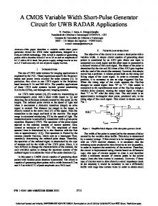
Fig. 1: 555 Timer as in an astable mode (multivibrator)
Figure 1 shows a 555 timer used as an astable multivibrator. In the astable circuit pin 2 is connected to pin 6, so as to allow a low voltage to be fed back to pin 2, which then triggers the circuit. A second resistor is added between pin 6 and pin 7 to shut down the discharge of the capacitor. The output duration is high and is given by equation 1, while the time for which it is low is represented as and is given by equation 2. (1) (2) The total duration ( ) for the oscillation is the sum of
and
* given by equation 3. (3)
The frequency (F) of the astable signal is determined by external components
and , which is given by equation 4. (4)
However, if
is larger than , then the mark space ratio is approximately equal to (5)
2.2
PRINCIPLE OF OPERATION OF PULSE TONE GENERATOR
The pulse to generator is based on two 555 timer ICs or a single 556 timer IC (which contains two 555 timer). The first is configured as a timer in a stable mode once triggered, it will emit a frequency from it output pin 3 that will drive Q1 transistor. Q1 transistor will then turn ON and OFF according to the frequency of the circuit, it will in turn use to drive an 8ohm loudspeaker to emit a loud audible sound. The astable frequency of the circuit is determined using equation 4: ISSN : 2351-8014
Vol. 25 No. 2, Jul. 2016
406
Ehiagwina Ojiemhende Frederick, Kehinde Oluseye Olufemi, Seluwa Emmanuel Oludare, Afolabi Lateef Olashile, and Yakub Bolaji Jamiu
Where Then, The frequency of the sound can be adjusted by appropriate choice of 2.3
,
and C .
PREVIOUS WORKS ON PULSE TONE GENERATOR
In this section, attempts are made to review past works on pulse tone generators. A pulse tonevgenerator for acoustic stimulation was applied in Evoked Response Audiometry by [7]. The system made use of Field Effect Transistor and triggering circuits with a random period mode. On the other hand, [8] highlighted 25 common things that can be done with function generator. While, solution was proffered by [9] for overcoming hindrances to test access points needed for instrumentationbased test for mixed-signal RF chip. It uses sigma-delta (∑∆) modulation technique and the same time developed two-tone RF generation for IP3/IP2 on-chip test based on a dedicated phase locked loop architecture. Reference [1] Constructed or designed a pulse tone generator with an astable wave form, uses two 555 timer, but he did not consider the (Pin 5) which is the control voltage and secondly he did not consider the C2 (Filtering Capacitor) in his project. While [2] designed a pulse tone generator with a Monostable or single pulse generation wave form. He used a 556 timer (which consist of two 555 timer) instead two 555 timer. His project requires triggering to vary the wave form, it is an unstable wave form because it requires triggers. Therefore, we are going to make an improvement on our work basically on their weak areas which speculated on pin 5 and C2. Additional, a lighter weight PVC casing will be used in contrast to metallic casings typically used.
3
DESIGN AND METHODOLOGY Figure 2 shows the block diagram of the system with its functional units.
Fig.2: Block Diagram of a the Pulse Tone Generator Based Alarm System
ISSN : 2351-8014
Vol. 25 No. 2, Jul. 2016
407
Design and Implementation of a Variable Pulse Tone Generator Based Alarm System for Emergency Signaling
The pulse tone generator operates with a dc power supply. The audio frequency generator automatically generates some noise immediately it is switched ON by an electronic switch and its output is increased by the amplifier. However, before amplification it may require triggering process if the signal is not in an astable waveform. The calibrating network receives part of the signal from the amplifier and the other signal goes to the power amplifier [10]. 3.1
CIRCUIT DIAGRAM OF THE PULSE TONE GENERATOR BASED ALARM SYSTEM
Fig.3: Circuit Diagram of the Pulse Tone Generator Based Alarm System [10]
3.2
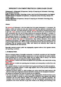
ADAPTED CIRCUIT OF THE VARIABLE PULSE TONE BASED ALARM SYSTEM
Some modifications were introduced into the circuit of fig. 3 which led to the circuit of fig.4a and b. The modification includes a variable resistor knob for varying tones generated. The modified circuit is simpler and cheaper because it consists of fewer number of components.
ISSN : 2351-8014
Vol. 25 No. 2, Jul. 2016
408
Ehiagwina Ojiemhende Frederick, Kehinde Oluseye Olufemi, Seluwa Emmanuel Oludare, Afolabi Lateef Olashile, and Yakub Bolaji Jamiu
Fig.4a: Modified Circuit Diagram of the Pulse Tone Generator Based Alarm System
Fig.4b: Power Supply unit of the Modified Circuit Diagram of the Pulse Tone Generator Based Alarm System
3.3
ANALYSIS AND DESIGN OF THE PULSE TONE GENERATOR BASED ALARM SYSTEM In this section the design for the system is made, especially the power supply unit
3.3.1
THE REGULATED POWER SUPPLY
The pulse tone generator requires 9 V DC and a current of 500 mA A centre tap transformer is used to step down the 220 V AC to 12 V AC Each of the 4 diode of the bridge rectifier drops 0.7V, but only 2 diodes operate per cycle.
ISSN : 2351-8014
Vol. 25 No. 2, Jul. 2016
409
Design and Implementation of a Variable Pulse Tone Generator Based Alarm System for Emergency Signaling
Therefore, the total voltage drop by the bridge rectifier The regulator used is 7809, and it is known that the 78XX series requires at least 2 V to operate, therefore we need at least 11 V from the rectifier’s output The AC input might varies by up to 10% But peak transformer voltage Minimum transformer voltage Hence, the ripple voltage (excess voltage that need to be filtered off by the capacitor In order to determine the value of the required filter capacitor, equation 6 is used. (6) (chosen) Therefore, However, a
can suffice.
The LED Resistor value, R is given by: (7) where: = supply voltage = LED Voltage (it is usually 2V for red LED and 4V for blue LED) = 20mA Hence, R6 = 350Ω 3.4
IMPLEMENTATION OF THE DESIGN
The pulse tone based emergency signalling alarm system is powered with 12 volts power supply, hence, the need to use a 220/12V, 500mA step-down transformer. The transformer output is rectified with the help of a diode as a rectifier after which the output was smoothed, so to remove the ac ripple from the circuit. The output is then used to power the circuit or system. This system makes use of the two NE555 timer and a 16 Ω, 3W loudspeaker marked LS1 in fig.4a. 3.5
CASING OF THE CIRCUIT
The case used for the project is made up of PVC materials. This material makes the casing for the system easier and lighter with the needed dimension (6cm ×6cm). Other advantages of using a PVC is to enhance the output of the system, and can be easily made in shapes, also it helps the system to look more presentable. Figure 6 shows the external features of the variable pulse tone generator based alarm system. Whereas the internal circuitry is shown in fig.7
ISSN : 2351-8014
Vol. 25 No. 2, Jul. 2016
410
Ehiagwina Ojiemhende Frederick, Kehinde Oluseye Olufemi, Seluwa Emmanuel Oludare, Afolabi Lateef Olashile, and Yakub Bolaji Jamiu
Fig. 6: External Features of the Variable Pulse Tone Generator Based System
Fig. 7: Internal Circuitry of the Variable Pulse Tone Generator Based System
4
CONCLUSION AND RECOMMENDATION
This project was designed and constructed as a portable device that will emit a loud enough sound through a suitable transducer (loudspeaker), if connected to a power supply. It is useful and applicable in various aspect of life since it is portable. It can also be placed in a vehicle, in time of emergency. One can easily switch it on and the loudspeaker will emit a loud sound that will frighten the intruder. Additionally, it can serve as typical burglar alarm system which can be placed at the entrance of a house.
ISSN : 2351-8014
Vol. 25 No. 2, Jul. 2016
411
Design and Implementation of a Variable Pulse Tone Generator Based Alarm System for Emergency Signaling
Future work could consider reducing the size of the cabinet, ensuring adequate ventilation of the system, improving the durability and reliability.
REFERENCES [1] [2] [3] [4] [5] [6]
J. Lawal, "Pulse Tone Generator for Home Burglar Alarm System," Offa, 2009. A. Aleshinloye, "Pulse Tone Generator for Car Touch Intruder Alarm," Offa, 2007. H. Davis and S. Zerlins, Acoustic Relation of the Human Vertex Potential, 1966. O. T. Adewumi, Electronic Communication, Offa: Olad Publisher, 2010. H. G. James, The Irwin Handwork of Telecommunication, A.R. Donelly and Sons Company, 2006. J. T. Ronald and S. W. Neal, Digital Systems Principles and Applications, 8th ed., Upper Saddle River, New Jersey, Columbus, Ohio: Prentice-Hall, 2001, pp. 412-483. [7] Stig D. Arlinger, "A Tone Pulse Generator For Acoustic Stimulation," Medical and Biological Engineering, vol. 7, pp. pp.627-632, 12 1969. [8] Tektronic, 23 08 2006. [Online]. Available: www.tek.com/dl/75w-23806-0.pdf. [9] S. Ahmad, "Stimuli Generation Techniques for On-Chip Mixed-Signal Test," Linkopings, 2010. [10] D. J. Comer, Electronic Design with ICs, Addison Wesley Publishing Company Inc., 1981. [11] D. M. Calcutt, Electronic Technology, Calcutt University.
ISSN : 2351-8014
Vol. 25 No. 2, Jul. 2016
412