Saeed Behzadipour et al. Emotional Learning Controller for a Robotic Laparoscopic Instrument
Design and Implementation of an Emotional Learning Controller for Force Control of a Robotic Laparoscopic Instrument Seyed Mohsen Khadem1, Saeed Behzadipour1,2,*, Mehrdad Boroushaki3, Farzam Farahmand1,2, Mahdi Tavakoli4 1. Department of Mechanical Engineering, Sharif University of Technology, Tehran, Iran. 2. Institute for Advanced Medical Technologies (IAMT), Tehran University of Medical Sciences, Tehran, Iran. 3. Department of Energy Engineering, Sharif University of Technology, Tehran, Iran. 4. Department of Electrical Engineering, University of Alberta, Edmonton, Canada.
Received: May 6 2014 Accepted: July 11 2014
A B S T RAC T Purpose: Force control of robotic instruments is a difficult task due to the uncertainties caused by changes in the instrument’s geometrical and mechanical characteristics during surgery as well as the nonlinear dynamics of the instrument. A new approach based on an intelligent controller is developed to control the force interactions of a robotic surgical instrument with delicate soft tissues. This feature assists the surgeon by providing a safe grasp of soft tissues during dissection or suturing. Besides, by controlling and optimizing the magnitude of the instrument/tissue contact forces, controlled grasp will significantly reduce the surgery trauma. Method: The controller is devised using a neuro-fuzzy regulator that receives the tracking error and its derivative as inputs, and a PD critic that evaluates the actual pinch force and produces an emotional signal. The controller tunes its parameters by means of minimizing the critic’s output signal, i.e., stress, so that the force tracking error is reduced. Numerical simulations and experimental tests were performed to evaluate the controller.
Keywords: Robotic Surgery, Neuro-Fuzzy Controller, Emotional Learning, Force Control.
Results: Simulation tests revealed that the controller can effectively adapt its rules when the instrument’s geometry and frictional behavior changes. The experiments revealed a settling time of 0.7 s with 3.1% overshoot. In comparison with a PID, the proposed controller reduced the mean squared error (MSE) by 94% for a target constant force, and 24% for a target sinusoidal trajectory. Conclusion: the proposed controller showed a superior performance in force control of tissue in safe grasp in comparison with a PID particularly for constant target forces.
1. Introduction
R
obotic surgery systems have eliminated many of the inherent limitations involved in minimally invasive surgeries such as low dexterity, surgeons’ fatigue, and poor ergonomics[1, 2]. Some other limitations of MIS, however, are still present in robotic surgery systems such as the lack of tactile sense that can negatively affect the efficacy and safety of surgery. With no or insufficient tactile information from the tool-tissue force
interactions, the surgeon might not be able to control the magnitude of the force he applies to the tissue properly, increasing the risk of surgery trauma [3]. As an attempt to remove this limitation, several sensor integrated laparoscopic instruments have been introduced in the last decade. However, there are still some challenges that impede their widespread application in robotic surgery systems. For instance, during a simple minimally invasive surgery, a variety of instruments with different tips and functionalities, e.g., cutter,
* Corresponding Author: Saeed Behzadipour, PhD Associate Professor, School of Mechanical Engineering, Sharif University of Technology, Azadi Avenue, Tehran, Iran. Tel: (+98) 21-66165542 / Fax: (+98) 21-66000021 E-mail:
[email protected]
168
August 2014, Volume 1, Number 3
grasper, dissector and needle holder, are usually used. For a force controller to be effective and safe, it should be able to handle such variations in the kinematics and dynamics of the system [4]. Another deterrent to the practical force control of robotic sensorized instruments is mechanical imperfection such as joint clearance and friction which may also change through time. Although these are ordinary qualities of any mechanical device, they become very annoying during the control of robot/human interaction, especially in dealing with delicate human organs. Thus, the controller should be also intelligent to identify instrument’s clearances and be robust against the change of its frictional behavior. Neural networks, with their intriguing properties such as learning ability, interpolation, parallel processing, and nonlinear function estimation, have been incorporated in many complex control problems. A neuro-controller in general, performs a specific form of adaptive control, with the controller in the form of a multilayer neural network with adaptable parameters defined as adjustable weights[5]. Alternatively, fuzzy controllers have been shown to work well as supervisory controllers in conditions involving high nonlinearities, time varying parameters or system uncertainties[6]. In order to realize the benefits of both Fuzzy and neural controllers, some modern intelligent methods have used neuro-fuzzy structures to combine the generalization capabilities of neural networks and the decision making competence of fuzzy systems [7, 8]. The heart of such intelligent control systems is a fuzzy controller whose parameters are self-tuned through a learning technique. Genetically optimized fuzzy controllers, back-propagation through plant and reinforcement learning have shown successful implementation of this method [9, 10]. Reinforcement learning is considered an effective learning technique, in which a critic agent gives rewards and punishments with respect to the states reached by the controller [11]. The advantages of this technique over previously used methods has been largely appreciated by the community [12] and it has been successfully implemented in a wide variety of applications, e.g., cars, missile guiding systems, steam generators etc.[13-15]. However, it suffers from a slow convergence speed and more importantly the critic`s hesitation for the failure of the controller and commencing to deliver correction signals [16]. This restricts the application of the reinforcement learning technique in zero-tolerance error systems such as robotic surgery in which any minor failure might lead to severe injury or huge financial loss.
A solution to this problem might be obtained using emotional based learning that integrates the sentimental factors into the decision making process. In general, decision making, even in case of human beings, is fully based on rationality and emotional cues are concealed [17]. However, the positive and important role of emotions in decision making has been recognized recently not only in psychology, but also in artificial intelligence and robotics [18]. For instance, Lucas developed a computational model based on the limbic system in the mammalian brain for control engineering applications [19]. He applied the proposed controller for some SISO, MIMO and nonlinear systems and the results demonstrated excellent control action, disturbance handling and system parameter robustness. In another work, Mehrabian et al. evaluated the performance of a proposed Brain Emotional Learning model by applying it on different nonlinear uncertain systems. The results showed very good adaptability and robustness, while maintaining stability [20]. In summary, emotional cues can provide an approximate method for selecting the appropriate actions, when uncertainties and limitations of computational resources interfere with the rational decision making. This feature can be used to develop an emotional based learning technique that generalizes the application of reinforcement learning and improves its performance. In this work, a novel emotional learning based intelligent controller is introduced and its application for force control of tissue grasp during a minimally invasive robotic surgery (MIRS) is addressed. The controller consists of a neuro-fuzzy regulator that receives the tracking error and its derivative as inputs, and a PD critic that evaluates the plant`s desired output and produces an emotional signal. The controller tunes its parameters by means of minimizing the critic’s output signal, i.e. stress, so that the tracking error is reduced. Moreover, the efficacy of the controller in controlling the tool- tissue force interactions is evaluated in a number of simulation and experimental tests.
2. Methods A mathematical model was developed to describe the mechanics of the robotic instrument and to represent its functional behavior. Then an emotional learning intelligent controller is introduced and the scheme of the proposed intelligent controller and the role of its elements are discussed.
169
Saeed Behzadipour et al. Emotional Learning Controller for a Robotic Laparoscopic Instrument
2.1. The Robotic Instrument
reference model of the instrument used for the simulation of the tool-tissue force interactions can be achieved:
The robotic laparoscopy instrument considered in this study is the end-effector of a slave robot [21], used in a haptic master-slave robotic surgery system. This 3-link serial spherical robot has a remote center of motion and includes 3 Degrees of Freedom (DoFs) for positioning the instrument during surgery.
2L a sin(θ ) + c )( b
= a cos(θ ) )] a sin(θ ) + c 2 1− ( ) b 2π 2π 1 2π ) + Jg ( ) + m ]θ + K T i ( N ) + mg − f g − f −[J m ( N l l N l Fj
[ −a sin(θ ) − (
j
(2)
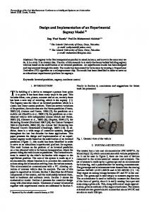
The force interactions of the instrument and tissue are measured using strain gauges installed on the instrument’s tip. In the present study, the instrument was a laparoscopic grasper with two strain gauges installed on both sides of one of the jaw`s tips. The target here is the control of the pinch force, i.e. the force exerted on the tissue by the jaws, using the output of the strain gauges as the feedback. Figure 1 shows a detailed view of the instrument. L is the contact length, i.e. the distance between the tissue contact point and the jaws pivot. a , b and c are geometrical parameters dependent on the jaw profile and θ is the jaw angle. Fj is the force at the tip of the jaws and Fi is the tool actuation force. Based on the geometrical equations that govern the instrument motion and the
virtual work principle ( 2.Fj .l.dθ − Fi .dx = 0 ) instrument`s dynamic model is as follows [22]:
F j=
a sin(θ + α 0 ) + c 1 )( Fi [−a sin(θ + α 0 ) − ( 2l b
a cos(θ + α 0 ) )] a sin(θ + α 0 ) + c 2 1− ( ) b
Figure 1. Geometrical parameters of laparoscopic instrument.
f g and f j are the gearbox and instrument joints` frictions, respectively. These two terms are estimated using conventional friction models. Actuator`s current
set point ( i ) is the model`s input and the output is the
(1)
exerted grasp force ( F j ).The parameters of the model as in (2), are given in Table 1:
In equation (1), we have neglected the effects of the weight of the tool tip. By implementing the dynamics of the motor and gearbox and the effects of the friction, the
In order to add the effects of the gearbox and the ball screw friction to the model, we used the friction estimation model developed by Canudas et al [23]. This
Table 1. Values of the laparoscopic instrument model parameters
170
Parameter
Description
Parameter
Description
Fj
tool-tissue interaction force
l
ball screw pitch
i
grasp motor current set point
fj
joints friction
KT
motor torque constant
fg
gearbox and ball screw friction
N
grasp motor gearbox`s transmission ratio
L
jaw pivot and tissue contact point distance (effective length of tip)
Jr
grasp motor`s rotor inertia
a , b, c
instrument jaw`s geometrical parameters
Jg
gearbox`s inertia
θ
instrument jaw angle
August 2014, Volume 1, Number 3
model is mostly used for actuator friction compensation in robot manipulators with low velocities. Since the instrument jaws move slowly during tissue grasping, this model seems appropriate for our study. The veracity of this model in predicting the actuators friction in mechanisms has been confirmed thanks to its vast applications in industrial robotic systems. Eq. (3) represents the friction model of the actuator in this robotic instrument:
f g =[α 0 + α1 (e
−β ω
) + α 2 (1 − (e
−β ω
))]sgn(ω ) (3)
where f g and ω are the actuator friction force and spindle drive angular velocity, respectively. The friction parameters α 0 , α1 + α 0 and α 2 are coulomb friction, static friction and viscous friction, respectively. β is a constant value.
Table 2. The values of the laparoscopic instrument model parameters. Parameter
Value
Parameter
Value
k
24.4 mNm/A
α2
0
N
720/25
β
20 sec/rad
l
2 mm
σ
0 N.m.sec/rad
L
18 mm
τ c1
1.6e-2 N.m
a
2.85 mm
τ s1
1.9e-2 N.m
b
5 mm
τ c2
1.85e-2 N.m
c
1.5 mm
τ s2
1.1e-1 N.m
α0
9.5 N
a1
55 sec/rad
α1 + α 0
14.3 N
a2
42 sec/rad
As Equations (2), (3) and (4a) indicate, the dynamics of the instrument is highly nonlinear. Also it is very susIn order to estimate the friction at the instrument ceptible to the geometrical parameters and the exact lojoints, we used the equation provided by Tavkoli et al. cation of the contact point of the instrument’s jaws and [24]. This model considers two rigid bodies in contact the tissue. In addition, the friction of the instrument’s through elastic bristles. The friction force/torque bejoints and the actuator are discontinuous and unstable tween the two bodies can be modeled based on their when velocity tends to zero. In here, the possibility of relative velocity ω and the bristles’ average deflection. such situations in which the value of the system paramBy assuming asymmetry in Stribeck friction affects eters are slightly different from their nominal ones are when the instrument moves in the positive and negative referred to as uncertainties and will distort the accurate directions, one can write: control of the tissue/instrument interaction forces. Another uncertainty comes from the fact that the friction −a ω −a ω −a2 ω −a2 ω ) + τvary τ j =σω + τ c 1 (1 − e 1 u ω ) + τ s 1 (e 1 u ω ) + τ c 2 (1 − e constants u −ωmay s 2 (e due touthe −ω )continuous use of the instrument. Therefore, a nonlinear controller is needed to −a ω −a ω −a ω + τ s 1 (e 1 u ω ) + τ c 2 (1 − e 2 u −ω ) + τ s 2 (e 2 u −ω ) control the tool-tissue force interactions which is also robust against the unpredictable variations of these pa(4a) rameters. In the next sections of this paper, an emotional learning intelligent controller is introduced for this ap2π fj =τ j (4b) plication and the effects of unpredicted changes in the l model parameters are investigated. where τ j , f j and ω are the joints friction torque, 2.2. Emotional Based Intelligent Controller joints friction force and angular velocity of the tool tip at the motor output shaft, respectively. The first term in Cognition and emotion are two prominent factors in Eq. (3a), σω accounts for the viscous friction. Friction pathe development of decision making skills in human rameters τ ci ,τ si and ai with i=1 correspond to the movebeings. Human cognition strength uses perception and ment of the tool tip in the positive direction (ωm > 0), and rationalization to take a decisive action. However, anfor the tip movement in the negative direction (ωm < 0) other important aspect of human`s mental life is emoi is set to 2. Also, u x is the step function, i.e. u x = 1 if x tion. The human`s actions are affected by sentimental > 0; and 0 otherwise. elements such as stress, satisfaction or excitement. Humans always try to reduce the stress or get excited by The reference model`s parameters for the robotic inachieving a certain goal [25]. Therefore, despite animal strument of our study are shown in Table 2. Since the learning which is proportional to the reinforcement coninstrument`s jaws move slowly during tissue grasping, tingency and the effects of reward and punishment, in the coefficients of the viscous friction were assumed to humans, other factors such as intensity and quality of be negligible.
171
Saeed Behzadipour et al. Emotional Learning Controller for a Robotic Laparoscopic Instrument
reinforcement and possession of stress or excitement are involved [26, 27]. In the last few years, a great attention has been devoted to develop a computational model for human emotional learning. Our model of emotional-based learning is in fact a cognitive restatement of reinforcement learning, firstly introduced in 1983 by Barto [28]. It includes a critic or supervisor that continuously compares the plant’s output with the desired target to produce a stress signal that modifies the controller. The main goal of the system is to minimize the critic`s stress (emotional) signal via updating and modifying the controller. The key difference between emotional learning and classic reinforcement learning is in the evaluating signal produced by the supervisor. In the classic reinforcement learning model, supervisor's signal, namely r, accepts binary values, i.e. r=+1 for total failure of the controller and r=0 if the controller meets the demands. However,
in the modern approach critic`s signal is allowed to take real values between -1, +1; where -1 and +1 describe the boundaries of the total failure, and the closer the signal to zero, the better the performance of the controller [29]. This means that the system does not wait for total failure of the plant. Instead, at each sample time, it updates the controller variables to minimize the critic`s output signal which is interpreted as emotional or stress signal. The emotional learning based controller consists of three main elements. The first one is a neuro-fuzzy controller that receives the current state of the plant as an input and issues the appropriate control signal. The critic agent assesses the behavior of the controller, criticizes it and provides the system with the stress signal. Finally, the learning element utilizes an optimization method to minimize the stress signal and modify the controller variables. Figure 2 shows structure of the proposed emotional learning based controller.
Figure 2. Structure of emotional learning based controller.
2.3. Neuro-Fuzzy Controller The model of Takagi-Sugeno-Kang (TSK) [30] is used here to develop the fuzzy controller. This model is characterized by N rules:
network (Figure 3). This network is equivalent to a 2-input and 1-output TSK controller with 4 rules. The first layer maps the input data into [-1, 1] interval. In the second layer, the inputs` degree of membership in fuzzy
Ri : If ( x1 is F ) and ( x is F ) and … and ( x is F ) 2 i1 n in i2
sets is calculated, giving an output as µ F ( x j ) . In the third layer, each neuron, by using the product-operator, multiplies the incoming inputs and establishes the antecedent
Then ci = gi ( X )
parts of the fuzzy rules, i.e.,
ij
(5)
where i = 1, 2,..., N are the number of rules; are the input variables;
Fij
x j ( j = 1, 2,..., n )
th
is the i linguistic value,
and ci = gi ( X ) is the consequence of the ith rule, where n gi : R → R . The
output of the TSK model is the weighted average of each rule’s output. Implementing the fuzzy system in the framework of a neural network would result in a six layer neuro-fuzzy
172
i
F1 × F2 ×...× F
. The fourth
layer normalizes the firing strengths, leading to an outN
put as ui
∑ u . The fifth layer uses TSK defuzzifier rule i =1
i
of (5) and the final output of neuro-fuzzy network is the summation of the fifth layer outputs. The last layer acts as a defuzzifier to determine the final output accordingly. For a 2-input 1-output TSK controller, the output is calculated as the following:
August 2014, Volume 1, Number 3
Figure 3. Sample neuro-fuzzy network equivalents with MISO fuzzy system with 2 inputs.
yi =
(ai u1 + bi u2 + ci )ui
(i = 1, 2,3, 4)
n
∑u i =1
(6)
E=
1 2 r 2
(8)
i
where ai , bi and ci are the coefficients of the TSK rules that are tuned via emotional learning.
This error function can be interpreted as the stress applied to the controller. The main goal of the emotional learning controller is to minimize the overall stress of the system.
2.4. Emotional Critic
2.5. Emotional Learning
In our proposed method, the critic`s inputs are the plant`s output error and its first derivative. The critic`s output signal is the commensurate emotional signal ( r ). We defined as a linear combination of the out-
As it was mentioned in the previous sections, the purpose of learning is to minimize the stress signal via updating the parameters of TSK controller. Here, we used the steepest decent method for adjusting the weights of the fifth layer of the controller:
put signal error = (e
yref − y
) and its first derivative.
y ref
stands for the reference input, i.e. the desired pinch force in the tool-tissue interaction, and y represents the actual output force. Therefore, the critic`s output is calculated as:
= r k1e + k2e
(7)
where r is the output signal of the critic, k1 and k2 are positive constants. This formulation, in fact, leads to a proportional-derivative (PD) critic. For instance, if the error of the pinch force is high but decreasing (negative derivative), then the performance of the controller is acceptable and a better performance is expected in future. As another example, if the error is low and its derivative has a large positive value, the critic should disapprove this as an unsatisfactory performance of the controller. These examples show the fuzzy nature of the critic itself. The critic`s signals are used to continuously update the TSK controller output layer parameters. The aim of the control system is to minimize the sum of the squares of the emotional signals. Thus, we can describe the error function, E, as the following:
∆w =−η
∂E ∂w
(9)
where η is the learning rate of the controller and w represents its tunable parameters ( ai , bi and ci ). By applying the chain rule, we have:
∂E ∂E ∂r ∂y ∂u = ∂w ∂r ∂y ∂u ∂w
(10)
The first term in the chain is obtained using (8): ∂E =r ∂r
(11)
∂y
Also ∂u is the Jacobin of the system, J , which represents the system`s gradient, i.e. the long term variation of the plant output with respect to the control signal. Estimating J with its sign would be sufficient and it can be simply found through a trial and error process. Therefore, using (11) and (10) along with (9), the adaptation rule of the tunable parameters is achieved as the following:
173
Saeed Behzadipour et al. Emotional Learning Controller for a Robotic Laparoscopic Instrument
∆w = η rJ
∂u ∂r ∂w ∂y
(12)
Hence, considering e and e as the neuro-fuzzy network inputs, in accordance to (12), (7) and (6), the update rules for a , b and c are given as [15]: ui
= aiold + η Jre ainew
n
∑u i =1
= biold + η Jre. binew
(13a)
ui n
∑u i =1
= c iold + η Jr c inew
i
(13b) i
ui n
∑u i =1
(13c) i
2.6. Control System Architecture The main objective of the force controller is to track a target pinch force, assumed to be both effective and safe, so that while the desired surgical function, e.g. su-
turing, dissecting, etc. is achieved, excessive harmful forces are avoided. Through tissue grasp, depending on the relative magnitude of applied forces, the tissue may slip, be damaged, or grasped successfully. When external pull forces are high compared to the pinch force, the tissue slips out of the forceps, whereas when both pull and pinch forces are high, the tissue might be damaged. This means that during an auto grasp, while external forces are applied to the tissue, the instrument should exert a controlled force to ensure that neither the tissue will damage nor it would slip [4]. The architecture of the designed controller, using the emotional based learning technique is shown in Figure 4. The desired pinch force is given as the system`s input and the control system determines the error and its derivative as inputs of the neuro-fuzzy controller. In order to track the desired pinch force, the parameters of the controller are continuously updated through emotional learning using (13a). The force interaction of the model with the soft tissue was modeled using two springs and dampers, attached perpendicularly to the instrument jaws. Using the data reported in the literature, the springs` stiffness and the damping coefficient were assumed to be 400 N m-1 and 5 N sec m-1, respectively [31].
Figure 4. Structure of the emotional learning based intelligent controller proposed for controlling the instrument’s pinch force.
Because of the large variations in the magnitude of error and its derivative as the inputs of TSK controller, the fuzzy system has five linguistic labels for each input, i.e., Negative (N), Small Negative (SN), Zero (Z), Small Positive (SP) and Positive (P). Thus, the neurofuzzy network includes 52 =25 rules in its rule base. We used Gaussian membership functions for Z, SN and SP, and Sigmoidal membership functions for N and P, as the following: µGaussian ( x : l ,= σ ) exp(−
µ sgm ( x : m, n) =
174
( x − l )2 ) σ2
1 1 + exp(−m( x − n))
(14a)
(14b)
where l , m , n and σ are the membership functions coefficients. As the values of these parameters change, the Gaussian and Sigmoidal functions vary accordingly, exhibiting various forms of membership functions on linguistic labels. Figure 5 illustrates the shape of the membership functions of TSK controller. A linear combination of error and its first derivative, i.e. linear PD, was chosen as the critic of the control system. In fact, a major advantage of our control system, in comparison with other intelligent controllers, is the insensibility of the critic to the exact values of its coefficients. We found the values of the critic coefficients by trial and error, in a way that the plant shows a reasonable and allowable response. These
August 2014, Volume 1, Number 3
coefficients were found in response to a step input signal in such a way that the error reaches zero in the fastest way without any overshoots. The final values obtained
for k1 and k2 were 8 ×10⁻² and 5 ×10⁻⁶ , respectively. Since the system`s output increased with increasing the input, J was estimated to be +1 .
Figure 5. Neuro-fuzzy network membership functions for (a) error (b) error derivative.
The main drawback of a linear PD critic arises from the fact that it might not be able to predict the nonlinear behavior of complex dynamics. The main solution is to use adaptive gains for the PD critic by means of a gain schedule [13]. Such a schedule can be achieved by an iterative trial and error process. However sometimes in practice, in systems such as ours, obtaining these gains might be very difficult. The reason is the unpredicted fluctuations in the magnitude of error and its derivative. In here, in order to enhance the controller`s performance and makes its response more accurate, we used adaptive learning rates. Firstly, we separated the learning rate of each input in (13a), which is responsible for tuning the parameters related to the system`s error. Then, we used (15) as the adaptation rule for tuning s in (13a): = η 100r + 2
(15)
and error procedure, to assign appropriate learning rates based on the magnitude of stress signal. In fact, using this method, we have given the critic the ability to act faster by choosing higher learning rates at the starting point, when the error is higher than normal. As the error becomes smaller and the learning element becomes weaker in tuning the controller parameters, the critic`s stress signal becomes inert. By assigning smaller learning rates, using (15), the performance of the learning element is enhanced and the controller accuracy in diminishing the error increases. In our study, the two other learning rates in (12b) and (12c) were kept constant at 0.01. 2.7. Experimental Setup This section describes the experimental setup that was used to evaluate the controller`s functionality, and compares its performance with a well-tuned PID controller.
where η is the learning rate for pinch force error and is the stress signal. Equation (15) was achieved in a trial
175
Saeed Behzadipour et al. Emotional Learning Controller for a Robotic Laparoscopic Instrument
The top and front views of the experimental setup, including a robotic gripper, a laparoscopic instrument, and a synthetic soft material are shown in Figure 6. The robotic gripper was an active mechanism which could easily hold different laparoscopic instruments and actuate them. The actuating system consisted of a servo DC motor, a gear head with spindle drive and an encoder. A graphite brushed 11WDC-motor (RE-max 24, Maxon Motor AG., Switzerland) with a digital servo drive (EPOS2, Maxon Motor AG., Switzerland), were used in combination with a spindle drive with 29:1 ratio, 6mm diameter ball screw, and 2mm lead (GP 22 S, Maxon
Motor AG., Switzerland). By means of a specially designed coupling, any conventional laparoscopic instrument could be connected to the actuation system. The coupling consisted of two parts, tube gripper that held the instruments tube still, and the insert gripper that connected the instrument`s insert to the actuation system. By pushing a button, the instrument could be simply released from the insert gripper, as shown in Figure 6. The instrument was mounted on a fixed support, designed for the experiment. During the tests, a rubber block with a 3 MPa Young’s modulus was used as the soft tissue.
Figure 6. Top and front views of the experimental setup.
Two small self-temperature-compensated strain gauges with a gauge factor of 2.11 (BFLA-2-8, TML Co., Ltd., Tokyo, Japan) were used to obtain the force feedback. The strain gauges were attached to the proximal parts of the jaws. They were wired into a Wheatstone bridge circuit with 10 V excitation voltages. Adjustable potentiometers were used to calibrate the output voltages. The output signal of the bridge was passed through a 10Hz low pass filter and amplified 1000 times by a dynamic load cell amplifier (DN-AM100, DACELL Co., Ltd., South Korea). Furthermore, the amplified voltage was digitized using a Quanser USB data acquisition card (Q8-USB, Quanser Inc., Ltd., Canada) with the sampling frequency set at 0.5 KHz. In order to calibrate the force sensors, the instrument`s jaw was held horizontally to act as a cantilever beam. A calibrated digital force gauge (FG-5005, Lutron Electronic Enterprise, Taipei, Taiwan) was mounted on a vertical test stand, with its tip placed vertically. The tip of the force gauge was lowered steadily, using the setup’s handle, so that a known force was applied perpendicular to the jaw. The external force was increased from zero to about 10N and then returned to zero and the outputs of the strain gauges, as
176
well as the digital force gauge reading, were recorded. This data, along with a linear regression model, were used to obtain the relationship between the pinch force and the amplified output voltage of the bridge. Figure 7 shows the architecture of the proposed force control scheme used in experiments. The strain gauge force feedback from the grasper jaw, i.e. the actual pinch force, and the desired pinch force were the control system`s inputs. The programming was done in Quanser hardware-in-the-loop environment which is supported by MATLAB.
3. Results 3.1. Simulation Results In this section, the simulation results of the designed control system are presented. The simulation was performed on the mathematical model of the instrument, described previously, using MATLAB. In the first simulation, the control system was used as a regulator to keep the pinch force constant at 0.5 N. This is an ap-
August 2014, Volume 1, Number 3
Figure 7. Architecture of the force control scheme of the instrument.
propriate pinch force for slip/damage free grasping of soft tissues, when there is no external pull or pinch force [4]. At first, the instrument started grasping the tissue with an insignificant constant force. After 0.5 sec, when the contact between jaws and tissue was established, the controller became initiated. The performance of the control system to reach the target force is illustrated in Figure 8. After a settling time of 2.7 sec, the target force was achieved by the controller. The disturbance in the pinch force before actuation of the controller was due to the impact between the instrument’s tip and the soft tissue. Figure 8 (b) illustrates the sequential trend of some chosen tuning parameters for the controller. As the time passed, these parameters were modified and the controller learned the appropriate rules to improve its performance. In order to investigate the controller robustness against model uncertainties, we simulated an abrupt 20% decrease in the friction of the instrument’s joints, after 5 sec from the start of the grasping procedure. Also, in two other simulations, the controller was tested for changes in the geometry of the instrument, when the jaws were 15% larger and when the effective length of the tip was decreased by 20%. Figure 9 shows the response of the proposed controller to these variations. As the controller encountered the sudden change in the friction at 5 sec from the starting point, it adapted the parameters of the control rules and improved its performance gradually. The oscillating disturbance with a maximum value of 0.73 N was damped after 0.48 sec. Also, replacing the instrument jaws had no major impact on the controller's performance.
Figure 8. Performance of the control system in simulation: (a) pinch force (b) sequential trend of the selected tuning parameters.
177
Saeed Behzadipour et al. Emotional Learning Controller for a Robotic Laparoscopic Instrument
Figure 10. Performance of the controller in tracking a target pinch force in simulation.
in particular to compare its performance with a welltuned PID controller.
Figure 9. Performance of the control system in simulation after (a) 20% decrease in the joint friction after 5 seconds (b) 15% enlargement of the instrument’s jaws.
Figure 10 shows the performance of the controller as a tracker. The desired pinch force was considered to have a second order polynomial profile, starting from 0.5 N and reaching 5 N in 5 seconds. This profile is consistent with the clinical practice considering the fact that surgeons manipulate delicate organs with caution and avoid applying fast movements and exerting continuous pinch forces larger than 5N. At first, the tracking error of the controller was considerable. However, in less than 0.1 seconds, the critic started modifying the controller parameters to decrease the error, and as soon as the controller reclaimed itself the error went to zero. 3.2. Experiments Results The implementation of the proposed emotional learning controller for the force control of the robotic laparoscopic instrument is presented here. Experiments were performed to evaluate the controller`s functionality, and
178
In the first set of experiments, the proposed control system was commanded to grasp the rubber band with a constant force of 1.5 N. Figure 11 illustrates the controller`s performance in two situations with different initial settings for the TSK’s coefficients. In the first experiment, the coefficients of the TSK controller were set randomly between 0 and 1. In the next experiment, we used the average values of these parameters, achieved through the first tryout, as the initial setting of the controller. As it can be seen, by using the trained controller, the performance of the controller was significantly enhanced. At the beginning of the real surgery, the controller can be simply trained through one controlled tissue grasp. In the next set of experiments, we evaluated the performance of the designed controller in tracking a force trajectory. The desired trajectory was a sinusoidal force with 0.08 Hz frequency. As illustrated in Figure 12, except for the peak of the first cycle, the performance of the emotional controller was more satisfactory than that of the PID in tracking the target pinch force profile. In fact, the intelligent feature of our emotional controller was well demonstrated in the trend of the resulting pinch force. The small deviation in the control action at the first peak was probably due to the adverse clearances in the instrument`s joints; it became considerable when the direction of the velocity changed. Although the PID`s response to this unsought disturbance was more favorable for the first cycle, the emotional intelligent controller tended to learn these sudden disruptions and provided improved responses in the next cycles.
August 2014, Volume 1, Number 3
Figure 11. Performance of the control system (in experiment) to achieve a target constant pinch force (a) untrained controller (b) trained controller.
4. Discussion The main reason to develop a sophisticated controller was the nonlinearities involved in the dynamics of the instrument and the uncertainties caused by the changes in its geometrical and mechanical characteristics during surgery. The designed controller included three elements: a neuro-fuzzy controller, a critic agent, and a learning element. The critic and learning elements were emotion based, to handle the uncertainties of the system and to react to the output errors faster, before a complete failure occurs. The performance of the controller was evaluated in a number of simulation and experimental tests. In simulation tests, the controller was examined for changes in the instrument geometry and frictional behavior, and was found effective in adapting the parameters of the control rules and improving its performance. The experimental results were also promising in
Figure 12. Performance of the controllers (in experiment) in tracking a sinusoidal pinch force (a) emotional controller (b) PID controller (c) tracking error.
179
Saeed Behzadipour et al. Emotional Learning Controller for a Robotic Laparoscopic Instrument
meeting the expectations. A settling time of 0.7 sec with 3.1% overshoot was achieved, using the trained emotional controller. In order to evaluate the performance of the designed intelligent control system in more detail, we compared the results of the controller with those of a PID that was well-tuned using Ziegler–Nichols tuning method. The comparison was performed quantitatively, based on the
mean square of error (MSE) index. Values of the MSE for the PID and the designed emotional control system in trained and untrained conditions are given in Table 3. In both cases, the emotional controller exhibited an enhanced performance in comparison with the PID. In particular, the trained emotional controller provided a reduction of 94% in the mean squared error (MSE) compared to the PID.
Table 3. MSE performance index for PID and emotional controller as regulators. Controller Type
PID
Emotional Controller
Trained Emotional Controller
MSE Index
0.0672
0.0297
0.0034
Table 4 shows the MSE index of the PID and the designed emotional controller in tracking a sinusoidal pinch force calculated in a 40 second interval. Similarly,
the emotional controller had an enhanced performance compared to a PID in tracking a sinusoidal trajectory, by providing a 24% lower MSE.
Table 4. MSE performance index for PID and emotional controller in tracking a sinusoidal pinch force. Controller Type
PID
Emotional Controller
MSE Index
0.1573
0.1194
The sequential trends of some of the tuning parameters of the controller are shown in Figure 13. Some parameters underwent constant changes during the experiment while others remained unaffected in the initial period of the test. The untouched parameters (such as b19 and c16 ) were coefficients of non-active rules in the initial period. As time passed and the controller faced new disturbances, new rules became identified, leading to sudden changes in the frozen parameters. Consequently, it could subtle the disturbances and resulted in lower errors compared to the PID in average.
5. Conclusions An intelligent controller based on emotional learning concept was developed for force control in robotic grasping of tissue in surgery. It was implemented on a robotic grasper which is made for a tele-surgery robotic system. It was shown by simulations and experiments that the application of such control scheme is more effective compared to a conventional PID controller. The main reason may be in the high variations of kinematics and dynamics characteristics of the plant during the course of surgery. The tests were designed to evaluate the performance of the controller using MSE index in maintaining a constant grasp force (as a regulator) and in tracking a desired pinch force. The tests were performed on a phantom test from synthetic materials. The proposed controller showed a significant improvement while performing as a regulator after the training is complete. In tracking control, the improvement was considerable but not as significant.
Acknowledgements
Figure 13. Sequential trend of the selected tuning parameters (in experiment) while tracking a sinusoidal pinch force.
180
The authors would like to acknowledge the Robotic Surgery Lab at Institute for Advanced Medical Technologies and particularly Dr. Mirbaghery for their support of this project.
August 2014, Volume 1, Number 3
References [1] S. Thielmann, et al., "MICA - A new generation of versatile instruments in robotic surg," IEEE/RSJ Intrnational Conference on Intelligent Systems (IROS), pp. 871-878, 2010. [2] A. Mirbagheri and F. Farahmand, "A triple-jaw actuated and sensorized instrument for grasping large organs during minimally invasive robotic surgery," Int J Med Robotics Comput Assist Surg, vol. 9, pp. 83-93, 2013. [3] M. MacFarlane, et al., "Force-feedback grasper helps restore sense of touch in minimally invasive surgery," Journal of Gastrointestinal Surgery, vol. 3, pp. 278-285, 1999. [4] E. A. M. Heijnsdijk, et al., "Slip and damage properties of jaws of laparoscopic graspers," Surgical Endoscopy, vol. 18, pp. 974-979, 2004. [5] P. K. Dash, et al., "Fuzzy and Neural Controllers for Dynamic Systems: An Overview," IEEE Proceedings of International Conference on Power Electronics and Drive Systems, vol. 2, pp. 810-816, 1997. [6] C. Von Altrock and J. Gebhardt, "Recent successful fuzzy logic applications in industrial automation," presented at the Proceedings of the fifth IEEE International Conference on Fuzzy Systems, pp. 1845-1851, 1996. [7] H. R. Berenji and P. Khedkar, "Learning and tuning fuzzy logic controllers through reinforcements," IEEE Trans. Neural Netw., vol. 3, pp. 724–740, 1992. [8] Z. HeydariI, et al., "Adaptive Neuro-Fuzzy Inference System for Classification of ACL-Ruptured Knees Using Arthrometric Data," Annals of Biomedical Engineering, vol. 36, no. 9, pp. 1449-1457, 2008. [9] A. Bergman, et al., "Adjusting parameters of genetic algorithms by fuzzy control rules," New Computer Techniques in Physics Research, pp. 235-240, 1994. [10] X. Xu, et al., "Efficient Reinforcement Learning Using Recursive Least-Squares Methods," Journal of Artificial Intelligence Research, vol. 16, pp. 259-292, 2002. [11] L. Jouffe, "Fuzzy inference system learning by reinforcement methods," IEEE Trans. Syst., Man, Cybern. C, Appl. Rev., vol. 28, no. 3, pp. 338-355, 1998. [12] A. H. Klopf, The Hedonistic Neuron: A Theory of Memory, Learning and Intelligence. Washington, DC: Hemisphere, 1982. [13] A. Fakhrazari and M. Boroushaki, "Adaptive critic-based neuro-fuzzy controller for the steam generator water level," IEEE Trans. On Nuclear Science, vol. 55, 2008. [14] H. Rouhani, et al., "Brain emotional learning based intelligent controller applied to neurofuzzy model of micro-heat exchanger," Expert Systems with Applications, vol. 32, pp. 911-918, 2007. [15] R. Farhangi, et al., "Load–frequency control of interconnected power system using emotional learning-based intelligent controller," International Journal of Electrical Power & Energy Systems, vol. 36, pp. 76-83, 2012.
[17] K. M. Galloti, Cognitive Psychology In and Out of Laboratory. Pacific Grove, CA.: Book/Cole, 1999. [18] J. Velasquez, "A computational framework for emotionbased control," in Proceedings Grounding Emotions in Adaptive System Workshop SAB’98, Zurich, Switzerland, 1998. [19] C. Lucas, et al., "Introducing BELBIC: brain emotional learning based intelligent controller," International Journal of Intelligent Automation and Soft Computing vol. 10, 2004. [20] A. R. Mehrabian and C. Lucas, "Emotional learning based intelligent robust adaptive controller for stable uncertain nonlinear systems," International Journal of Computational Intelligent, vol. 2, p. 2005, 2005. [21] A. Alamdar, et al., "Design of a 4 DOF Laparoscopic Surgery Robot for Manipulation of Large Organs," Studies in Health Technology and Informatics, vol. 173, 2012. [22] S. M. Khadem, et al., "Design and fabrication of a 2 DOF Haptic End-effector to be used in a Tele-Operation Surgery," in Iranian International Conference on Biomedical Engineering (ICBME) Tehran, Iran, 2011. [23] D. W. Canudas and B. Armstrong-Hélouvry, "A survey of models, analysis tools and compensation methods for the control of machines with friction," Automatica, vol. 30, pp. 1083-1138, 1994. [24] M. Tavakoli, et al., "A haptic interface for computer-integrated endoscopic surgery and training," Virtual Reality, vol. 9, pp. 160-176, 2006. [25] M. Fatourechi, et al., "Control effort reduction using emotional learning. ," in Proceedings of the Ninth Iranian Conference on Electrical Engineering, 2001, pp. 41-1 to 41-4. [26] R. W. Kentridge and J. P. Aggleton, "Emotion: sensory representations, reinforcement and the temporal lobe," Cognition and Emotion, vol. 4, pp. 191–208, 1990. [27] S. S. Khorramabadi, et al., "Emotional learning based intelligent controller for a PWR nuclear reactor core during load following operation," Annals of Nuclear Energy, vol. 35, pp. 2051-2058, 2008. [28] A. G. Barto, et al., "Neurolike adaptive elements that can solve difficult learning control problems," IEEE Transaction on System, Man and Cybernetics, vol. SMC-13, pp. 834–846, 1983. [29] H. R. Berenji and P. Khedkar, " Learning and tuning fuzzy logic controller through reinforcements," IEEE Transactions on Neural Networks, vol. 3, pp. 724–740, 1992. [30] T. Takagi and M. Sugeno, "Fuzzy identification of systems and its applications to modeling and control," IEEE Transaction on Systems Man and Cybernetics, vol. 15, pp. 116–132, 1985. [31] J. Rosen, et al., "Biomechanical Properties of Abdominal Organs In Vivo and Postmortem Under Compression Loads," Journal of Biomechanical Engineering, vol. 130, p. 021020, 2008.
[16] C. K. Lin, "Adaptivecritic autopilot design of bank-to-turn missles using fuzzy basis function networks," IEEE Transaction on System, Man and Cybernetics, vol. 35, pp. 197-207, 2005.
181