Internet Protocol (IP) based surveillance security .... From the block diagram,
figure .... Figure 1 Schematic representation of PC based IP surveillance security.
IJCSI International Journal of Computer Science Issues, Vol. 9, Issue 5, No 1, September 2012 ISSN (Online): 1694-0814 www.IJCSI.org
391
Design and Implementation of an IP-Based Security Surveillance System Cletus O. Ohaneme1, James Eke2, Augustine C.O. Azubogu3, Emmanuel N. Ifeagwu4 and Louisa C. Ohaneme5 1
Department of Electronic and Computer Engineering, Nnamdi Azikiwe University Awka, Anambra State, Nigeria. 2
Department of Electrical/Electronic Engineering, Enugu State University of Science & Technology (ESUT) Enugu, Nigeria.
3
Department of Electronic and Computer Engineering, Nnamdi Azikiwe University Awka, Anambra State, Nigeria.
4
Department of Electronic and Computer Engineering, Nnamdi Azikiwe University Awka, Anambra State, Nigeria.
5
Department of Computer Engineering Federal Polytechnic Oko, Anambra State, Nigeria.
Abstract The tremendous loss of lives and properties that may be attributed to criminals in recent times worldwide has become a source of worry to all and sundry. The situation has come to the alarming rate that the authority has sought for the immediate means of checkmating it without delay. Therefore, this work centers on the design and implementation of an Internet Protocol (IP) based surveillance security system. It incorporates remote viewing and storage of live video feeds and also remote motion control of the camera, all monitored with the use of a Personal Computer (PC). All the designs in this paper are software based. Hence the software applications are developed using Visual C-Sharp (C#) programming language to enable the proper monitoring and control of the entire system in which video feeds from the camera are viewed and also recorded on PC. The result obtained showed that with proper implementation, the surveillance system was found to be superb in all its ramifications. Keywords: Surveillance security system, visual CSharp, PC, passive infrared detector, camera.
1. Introduction The alarming crime rate in various homes and offices around the globe has necessitated the installation of surveillance security systems in most establishments. The security threats ranging from armed robbery, kidnapping and recently bomb blasts has kept the entire regions on their toes to the extent that no one can be sure of his/her security in the next moment. Surveillance is the systematic investigation or monitoring of the actions or communications of one or more persons in a place [1]. Surveillance security systems monitor the activities that go on in areas of the establishment with the use of surveillance cameras. The cameras may be stationary or it may rotate in different directions to achieve more coverage of activities in an
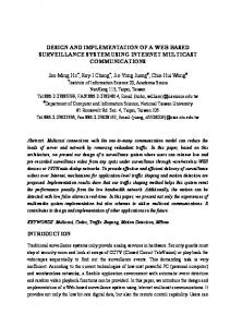
area. Such rotation of cameras is achieved with the use of DC motors or stepper motors. Currently, emergence of personal computers made security operatives to be efficient and equal to the task in keeping the entire populace to abreast with the latest security challenges in the course of discharging their duties. The PCs replace the close circuit television which had been in use prior to the emergence of IP-based surveillance system. So with this development in the security monitoring system, it is becoming apparent that acquisition of PCs by individuals is becoming mandatory if one should meet up with security challenges around his vicinity. With flexibility of surveillance security systems being a major consideration, this work focuses on the software designs and implementation of a system that enables a remote personal computer (PC) which is connected to a wireless local area network to view the activities captured by a surveillance camera. The PC also controls the direction of rotation of the camera remotely, with the use of a pair of wireless transceivers. Due to its wireless nature and its use of IP (Internet Protocol) data packets, this system provides remote access and greater flexibility compared to other visual surveillance systems, as the system can be hosted on the internet and thus made accessible from anywhere in the world. Figure 1 gives the schematic representation of the IP based surveillance security system which is developed in this paper. For rotation of the camera in different directions, a user interface application on the PC sends data through the PC serial port, MAX 232 and microcontroller (A) to microcontroller (B) wirelessly by means of the RF transceivers (A and B). The RF transceivers
Copyright (c) 2012 International Journal of Computer Science Issues. All Rights Reserved.
IJCSI International Journal of Computer Science Issues, Vol. 9, Issue 5, No 1, September 2012 ISSN (Online): 1694-0814 www.IJCSI.org
have a coverage distance of about 50 meters radius. Microcontroller (B) then generates the signal used to drive the DC motor in the camera holder on which the camera is mounted, thus the camera rotates in different directions. To view video feeds from the camera, the camera sends its video feed wirelessly to the router which then broadcasts this feed wirelessly to any authorized PC connected to the router. The router has a radial coverage distance of about 140 meters. Another user interface application on the PC is then used to view and record sessions of the video feed. Both user interface applications are developed using Visual C# (Visual C-Sharp) programming language. The applications developed are implemented to enable the user to view video feeds from the camera as well as to record video footage of events and save the recorded footage on the PC. The developed system also has playback capability which can play saved video footage whenever the user wishes to do so. There is no limit to the number of cameras that this application can accommodate. As long as the cameras are assigned an IP (Internet Protocol) address by the router, the camera video feed can be displayed by the application. The ‘Camera Motion Control’ application controls the direction in which the camera faces. It is equipped with a ‘user-control mode’ and an ‘auto-control mode’. The ‘user-control mode’ allows the application user to control the camera at will to face any direction along a horizontal plane while the ‘auto-control mode’ controls the camera in a timed manner, to rotate in both left and right directions along a horizontal plane. There had been another technique called intrusion detection system which is designed to detect unauthorized entry into a building or area. It consists of an array of sensors, a control panel and alerting system. Sensors detect intruders by many methods such as monitoring door and window contacts, hallways, by infrared motion detectors (active and passive types), ultrasound motion detectors etc. The sensors may be directly wired to a control panel that provides sensor power, or may communicate wirelessly. The active infrared detectors use a transmitter to send a beam of invisible infrared light to a receiver which monitors the received signal and can detect changes in the signal caused by attempts to pass through the beam [2]. Using the active infrared as a sensor to detect intrusion has advantages of fast response, and is insensitive to mechanical and acoustics noise. However this system can only be used to detect intrusion in an idle area
392
with no motion and does not provide facial recognition of the intruder. In the work presented by [2], Passive Infrared Detector (PIRD) was used as one of the most common detectors found in household and small business environments. The term passive means the detector is able to function without the need to generate and radiate its own infrared energy (it does not emit infrared beam but passively accepts incoming infrared beam). All objects emit what is known as black body radiation. It is usually infrared radiation that is invisible and can be detected by electronic device designed for such a purpose. PIRDs are able to distinguish if an infrared emitting object is present, by first learning the ambient temperature of the monitored space and then detecting a change in the temperature caused by the presence of an object. Using the principle of differentiation, which is a check of presence or absence, PIRDs verify if an intruder or object is actually present. PIRD motion detectors can be falsely triggered by warm air movement or other disturbances that can alter the infrared radiation level in an area. This system can only be used to detect intrusion in an idle area with no motion. It cannot be used in busy areas where movement and activities are executed. Also, this system does not provide facial recognition of the intruder. [3], in their own work introduced ultrasonic detectors to enhance the security of lives and properties. Ultrasonic detectors are active detectors that transmit ultrasonic sound waves, of frequency between 15KHz and 75KHz, that are inaudible to humans. The ultrasonic detector operates by the transmitter emitting an ultrasonic signal into the area to be protected. The sound waves are reflected by solid objects (such as the surrounding floor, walls and ceiling) and then detected by the receiver. When the objects are stationary, the frequency of the waves detected by the receiver will be equal to the transmitted frequency. However, a moving body causes a shift in phase of the ultrasonic signal received. A phase comparator detects the shift in phase and sends a triggering pulse to an alarm. Ultrasonic motion detector has the advantage that they are very sensitive and extremely fast acting. However, it has the disadvantage of responding to normal environmental vibration that can be caused by a passing car or a plane overhead. This system can only be used to detect intrusion in an idle area with no motion. It cannot be used in busy areas where movement and activities are
Copyright (c) 2012 International Journal of Computer Science Issues. All Rights Reserved.
IJCSI International Journal of Computer Science Issues, Vol. 9, Issue 5, No 1, September 2012 ISSN (Online): 1694-0814 www.IJCSI.org
executed. Also, this system does not provide facial recognition of the intruder.
Besides, there had been an existing monitoring system known as Closed Circuit Television (CCTV) which had been in use. A major setback with CCTV systems is its fixed nature and lack of flexibility. The monitor on which activities are viewed is always at a fixed position, thus for effective real time surveillance monitoring, the security personnel must always be at the position where the monitor is permanently stationed which is quite tasky if long hours are to be involved [4].
All the shortcomings of the already developed existing security systems are taken care of by the introduction of a PC based surveillance system. In this system, a typical IP (Internet Protocol) video surveillance system which is PC controlled (using serial communication for the interfacing), IP cameras are used. The cameras are IP addressable, thus they can be accessed from anywhere in the world via the internet or any wide area network (WAN), provided the user has the sufficient network access and security privileges to the camera. The IP camera is connected directly to a Local Area Network (LAN) and transports digital video signals across the network via Unshielded Twisted Pair (UTP) cabling (or by wireless means), to any PC or server on the network which views the video feeds received and records the video footage for future use. The network over which the camera transports the digital video signal is entirely wireless, thus the PC on which surveillance footage is viewed is not limited to a particular position. As long as the PC is within the coverage area of the wireless network, video surveillance can be viewed on the PC irrespective of location. Also smart phones and Personal Digital Assistants (PDA) with Wi-Fi capabilities can be used to view video footage from the camera, thus providing increased flexibility. Serial communication is used to interface a PC to the camera holder so that the direction in which the camera holder rotates the camera is controlled by the PC. Serial communication is a mode of data transfer where only one bit of data is transferred at a time [5]. This surveillance system overcomes the limitations of the existing systems described previously in the following ways [6]:
IP Cameras are used wirelessly to monitor both idle and busy areas.
393
IP cameras with motion detection capabilities can be used to detect motion in idle areas. IP cameras produce higher image resolution. Larger pictures with more image detail and clearer image quality are produced. IP cameras provide advanced PTZ features (i.e. pan, tilt, zoom) and the transmission of the commands is via a single network cable. Encryption & authentication: IP cameras offer secure data transmission through encryption and authentication methods such as WEP, WPA, WPA2, TKIP, and AES. Flexibility: IP cameras and PCs can be moved around anywhere when integrated on a wireless IP network. Remote accessibility: live video from selected cameras can be viewed from any computer, anywhere, and also from many mobile user and other devices. Better wireless reception and security: Interference is not a problem with wireless IP based systems. Digital video from IP cameras can be encrypted, thus providing security from unauthorized persons.
2. System Design As stated earlier in this work, the entire system is software-based design. It comprises of two major parts: (a) PC based control of camera rotation, and (b) Remote viewing of video feeds from camera. However, these two parts are achieved respectively using; (i) Computer interfacing by means of serial communication, and (ii) Streaming of digital video feeds across a wireless IP network. Computer interfacing can be defined as the art of connecting computers and peripherals together, so that both devices can communicate with each other. From the block diagram, figure 1, it is seen that it is microcontroller (B) that drives the external device which in this case is the DC motor contained in the camera holder. Thus the actual interfacing is between the PC and microcontroller (B). To achieve interfacing between the PC and microcontroller (B), microcontrollers (A and B) are both programmed with instructions which they execute. The microcontrollers perform their various functions by executing the instructions programmed into them. A camera motion
Copyright (c) 2012 International Journal of Computer Science Issues. All Rights Reserved.
IJCSI International Journal of Computer Science Issues, Vol. 9, Issue 5, No 1, September 2012 ISSN (Online): 1694-0814 www.IJCSI.org
control application is developed and installed on the PC. This application establishes connection between the PC and the external circuit, and sends serial data to the external circuit through the serial port.
2.1 Streaming Live Video Feed Streaming involves sending video/audio feed in compressed form over a network and the video/audio is displayed to the viewer in real time. With streaming video or streaming media, a user does not have to wait to download a file to play it. Instead, the media is sent in a continuous stream of data and is played as it arrives. The user needs a stand-alone player, which is a special program that uncompresses and sends video data to the display and audio data to speakers [7]. A plug-in that works as part of a Web browser can also be used to view and listen to the video/audio stream. In a live broadcast, the video signal is converted into a compressed digital signal and transmitted from a special Web server that is able to do multicast, i.e., sending the same file to multiple users at the same time. In a multicast stream, one stream of data travels to a router, which copies the stream and sends it to multiple viewers [8]. With digital technology, a digital (IP) camera translates the viewed image into digital signals which it then converts (encodes) into a series of IP packets that can be sent out over an IP-based network as a data stream. The IP network may be a local area network, a company wide area network, or even the public internet. At the destination, the receiver re-assembles these packets back into the original video stream [9]. The reconstructed video can then be viewed, stored, searched, replayed, or retransmitted to virtually any location anywhere in the world. An IP camera, also known as a network camera is a combination of a camera and a computer. The camera can be connected directly to a network. An IP camera consists of 3 main components:
Camera Encoder Server (web server, streaming server)
The camera and microphone are both input transducers that capture images/sound and transform them into electrical signals which are analog in nature. The Encoder converts the analog video/audio signal to digital format (raw video) and compresses (encodes) the raw video using a video codec (compression/
394
decompression) e.g. M-JPEG, MPEG4 (H.264) [10]. Compression makes the video streamable by discarding unnecessary data, lowering the overall resolution and taking other steps to make the video feed smaller. For storing and transmitting images over a network, they must be compressed or they will consume too much disk space or bandwidth. Audio is normally encoded using an audio codec e.g. AAC, AMR, MP3. Encoded audio and video streams are assembled in a container bit-stream or wrapper such as FLV, 3gp, AVI, MJPEG, MPEG4. The above data (wrapper of 3gp, MJPEG or MPEG4) contains both the audio and video as two different "channels". The web server hosting the Web page requests the bit-stream from the streaming server [8]. The bit-stream is delivered from a streaming server to a streaming client using a transport protocol, such as Real-time Transport Protocol (RTP). The streaming client, which is a PC, may interact with the streaming server using a control protocol, such as RTSP (Real-time Streaming Protocol). However, the PC is connected to the camera using RTSP. RTSP can be seen as the remote control for streaming and the remote has selected play so that the packets start being sent to you. The packets are UDP (User Datagram Protocol) or RTP packets, basically the same thing. The PC then uses a similar codec to repack the data stream received and decodes it to reconstruct the video and audio which can be displayed using a player or a web browser. For the interfacing process, 3 main programs are designed. Two programs are for the two microcontrollers (A and B) while the last program is the application for controlling the camera motion. The video streaming aspect of this work requires just one software to be designed and developed. It is the video player software which displays the real time video feeds from the camera.
Motion Control Application
This application allows the user to select the mode in which the camera motion operates and also to select the direction of motion, based on the mode selected. There are two modes: Auto control mode and User control mode. The interface of this application contains the following components: Serial-communications control, Auto mode radio button, User mode radio button, LEFT direction check box, RIGHT direction check box, LEFT motion radio button, RIGHT motion radio button, Mode/motion monitor label, and CLOSE button.
Copyright (c) 2012 International Journal of Computer Science Issues. All Rights Reserved.
IJCSI International Journal of Computer Science Issues, Vol. 9, Issue 5, No 1, September 2012 ISSN (Online): 1694-0814 www.IJCSI.org
The flow chart for the camera motion control application shows the sequence of operation of the application. The flow chart for the application is shown in figure 2.
The flow chart for the add/select camera and the add/select view functionality the application provides to the user is shown in figures 3(a) and 3(b).
Microcontroller Programs
Two microcontrollers are involved in this work and each of them is being controlled by a program. One of the programs allows the microcontroller (A) to receive data from the PC via one of the pins. The program sets the transceiver (A) in Tx (transmitter) mode and then generates and sends the appropriate data to transceiver (A) based on the data it received from the PC. This program is written in C (high level programming language). Another program allows the microcontroller (B) to sets the transceiver (B) in Rx (receiver) mode. Microcontroller (B) receives a stream of data from transceiver (B) and then it sets or clears the two of the pins of the system depending on the data stream it received from transceiver (B). This program is also written in C (high level programming language). These written programs are burnt into these microcontrollers for effective control of the system. 2.2 Mobility of the Cameras This application allows the user to add/select a camera whose video stream will be displayed, to add/select the pattern of view in which the camera video will be displayed, record the frames gotten from the camera as images in the JPEG format and also play back the stored recording from a camera at a specific date. The flow chart for the camera vision application shows the sequence of operation of the application.
DC motor in camera holder
IP camera
Microcontrolle r (B)
3. System Implementation and Analysis The implementation of this work is entirely software based which gives the interrelationship between the camera and the personal computers that may be attached to the network system. It therefore involves proper interfacing of the camera in motion and the PC for proper monitoring and documentation so that the security system will be effective and efficient. Interfacing is also between the PC and the DC motor which shows the angle at which the camera is to be moved for proper surveillance. Figure 3 shows the sequence of operations on how a particular camera can be selected to view the event that are going on within the area of coverage or to play the events that had been earlier recorded. Figures 4 and 5 show the flow diagrams of the sequence of operations of the microcontrollers that perform the interfacing capabilities between the two microcontrollers and the PC. Interfacing also involves communication between the PC and the DC motor which will be controlled by the PC. Serial communication between the PC and the DC motor is used to achieve the interfacing. The realization of the interfacing actions is by the use of software known as Visual C-Sharp (C#) language. The results obtained when implemented were found to be efficient in operation.
RF Wave (2.4 GHz) Transceiver (B)
395
Transceiver (A)
Microcontrolle r (A)
Linksystem wireless router
Figure 1 Schematic representation of PC based IP surveillance security
system
Copyright (c) 2012 International Journal of Computer Science Issues. All Rights Reserved.
MAX 232
PC
IJCSI International Journal of Computer Science Issues, Vol. 9, Issue 5, No 1, September 2012 ISSN (Online): 1694-0814 www.IJCSI.org
396
Start
Select Camera
Enter URL for Camera
Auto mode selected
Mode Selected?
User mode selected
User mode is disabled
Auto mode is disabled
Auto mode Selected displayed
User mode selected displayed
Select direction in which auto motion starts
Select direction of motion
Left direction selected
Direction Selected?
Right direction selected
left direction selected
Direction Selected?
Left motion in progress displayed
Right direction selected
Right motion in progress displayed
Auto motion control in progress displayed
Stop
Figure 2: Flow chart showing the sequence of operation of the Camera Motion Control application
Copyright (c) 2012 International Journal of Computer Science Issues. All Rights Reserved.
IJCSI International Journal of Computer Science Issues, Vol. 9, Issue 5, No 1, September 2012 ISSN (Online): 1694-0814 www.IJCSI.org
397
Start Start Add View Add Camera Enter View name, number rows, number of columns
Enter URL for Camera
Enter User name and password
Select view
Add Camera to View Select Camera Logged in
No Logged In?
No
Yes Viewing camera X-frame per second
Yes Viewing camera X-frame per second
Stop Stop (a)
(b)
Figure 3 (a): Flow chart showing the sequence of operation of the add/select view operation, (b): Flow chart showing the sequence of operation of the add/select camera operation
Copyright (c) 2012 International Journal of Computer Science Issues. All Rights Reserved.
IJCSI International Journal of Computer Science Issues, Vol. 9, Issue 5, No 1, September 2012 ISSN (Online): 1694-0814 www.IJCSI.org
398
Start
Assign the names; MISO, MOSI, SCK, CE, CSN, IRQ to pins
Create data variable character_rx
Execute a delay
Initialize the SPI control lines CE, MOSI, CSN, SCK to 0, 0, 1, 0 respectively
Initialize the special function register for serial communications. SCON=0x50, TMOD=0x20, THI=0xFD, TI=1, TRI=1
Execute a delay
Configure transceiver registers to accept data
Execute delay
Wait for data input from pin 10
Is data=’A’? Yes Transmit stream of byte “Fan Off”
No
Is data=’B’? Yes
Transmit stream byte “Fan On”
No
Is data=’C’? Yes
Transmit stream of byte “Lamp Off” to MOSI
No Is data=’D’?
No
Yes Transmit stream of byte “Lamp On” to MOSI
Figure 4: Flow chart showing the sequence of operation of the program for microcontroller (A)
Copyright (c) 2012 International Journal of Computer Science Issues. All Rights Reserved.
IJCSI International Journal of Computer Science Issues, Vol. 9, Issue 5, No 1, September 2012 ISSN (Online): 1694-0814 www.IJCSI.org
399
Start Assign the names; MISO, MOSI, SCK, CE, CSN, IRQ to pins
Create data variable char_rx
Execute a delay
Initialize the SPI control lines CE, MOSI, CSN, SCK to 0, 0, 1, 0 respectively
Initialize thespecial function register for serial communications. SCON=0x50, TMOD=0x20, THI=0xFD, TI=1, TRI=1
Execute a delay
Configure transceiver registers to accept data
Execute delay
Wait for data input from pin 10
Is data=’A’? Yes Clear FAN
No Is data=’B’? Yes Set Fan
No Is data=’C’? Yes Clear Lamp
No Is data=’D’?
No
Yes Set Lamp
Figure 5: Flow chart showing the sequence of operation of the program for microcontroller (B)
Copyright (c) 2012 International Journal of Computer Science Issues. All Rights Reserved.
IJCSI International Journal of Computer Science Issues, Vol. 9, Issue 5, No 1, September 2012 ISSN (Online): 1694-0814 www.IJCSI.org
4. Conclusion The feeling of being secured is second to none and this has made security a primary concern everywhere and for everyone. Every person wants his home and properties to be secured, while business organizations spend heavily for the security of their domain and assets. This paper has firmly presented the idea of IP video surveillance with great details on flexibility, remote access and remote control. This model is appropriate for securing homes, industries and offices. The work on the development of the PC based IP Surveillance Security System can be improved upon by the use of a DC stepper motor in the design of the camera motion control mechanism because a stepper motor rotates in steps slow enough for the camera to produce clear videos so that persons and things can be appreciably recognized as the camera is in motion.
References [1]
L. Franck, "Encryption and Cryptosystems in Electronic Surveillance: A Survey of the Technology Assessment Issues", 2001
[2]
M. Walker, "Electronic Security Systems", University Press, Cambridge UK, 2008, pp 66-75.
[3]
T. Weber, "Alarm Systems and Theft Protection", Stoneham Publishers, Buttersworth, 2006 pp 33-45.
[4]
E.L. Keifer, “The cons of analog cameras”, http://ipvideomarket.info/report/cctvsurveillance.htm August, 2011.
[5]
G. Mary, “Serial Port Communication”, http://beyondlogic.org/serial/serial.htm, July, 2011.
[6]
A.M. Tony, “IP camera: advantages”, http://en.wikipedia.org/wiki/IPcamera.htm July, 2011.
[7]
R. Bret, "Streaming Video", http://searchunifiedcommunications.techtar get.com/streaming-video.htm August, 2011.
[8]
V.W. Tracy, "How Streaming Video and Audio Work? ", http://howstuffworks.com/internet/basics/st reaming-video-and-audio3.htm August, 2011.
[9]
J. Anthony, "Streaming Video over Wireless Networks",
400
[10]
C.U. Xenny, "How does an IP Camera Works?", http://answers.yahoo.com/question/index.ht m, August, 2011.
[11]
B.C. Ying,“The Windows Serial Port Programming Handbook”, Auerbach Publishers, New York, 2005, pp 183-293.
Authors’ Profiles Cletus Ogbonna Ohaneme obtained B.Eng. in Electrical/Electronic Engineering in 1994 and M.Eng. in Telecommunication Engineering in 2000 respectively, both from Enugu State University of Science and Technology (ESUT) Enugu Nigeria. He is presently a lecturer in the Department of Electronic and Computer Engineering Nnamdi Azikiwe University Awka, Anambra State Nigeria. Also he holds PhD degree in Communication Engineering from the Department of Electrical/Electronic Engineering of Enugu State University of Science and Technology (ESUT) Enugu, Nigeria, with research interest on Wireless Network Capacity Improvements and Spectrum Management Systems. James Eke obtained his B.Sc. in Solid State Electronics and M.Sc. in Electronics from University of Essex, England in 1980 and 1981 respectively. He also obtained his M.Eng. in Electrical/Electronic Engineering and PhD in Communication Engineering from Enugu State University of Science and Technology (ESUT) Enugu, Nigeria in 1995 and 2006 respectively. Presently, he is a senior lecturer in the department of Electrical/Electronic Engineering, Enugu State University of Science and Technology (ESUT) Enugu, Nigeria. Augustine C. Okwudili Azubogu holds B.Eng. in Electronic Engineering from University of Nigeria Nsukka in 1986, M.Eng. Telecommunications Engineering from University of Portharcourt Nigeria in 2004, and PhD in Telecommunications Engineering from Nnamdi Azikiwe University Awka, Nigeria in 2011. He is currently a lecturer in the Department of Electronics and Computer Engineering of Nnamdi Azikiwe University, Awka, Nigeria. Emmanuel Ncheta Ifeagwu holds B.Eng. in Electrical/Electronic and Computer Engineering from Nnamdi Azikiwe University Awka, Nigeria in 2004. He also holds M.Eng. in Communication Engineering from University of Benin, Edo State, Nigeria in 2008. He is also a lecturer in the Department of Electronic and Computer Engineering Nnamdi Azikiwe University Awka, Nigeria. Currently he is pursuing his PhD programme in the department of Electrical/ Electronic Engineering Enugu State University of Science and Technology (ESUT) Enugu, Nigeria. Louisa Chizoba Ohaneme holds BSc. in Computer Science from University of Nigeria Nsukka in 2000, and M.Sc. in Computer Science from Nnamdi Azikiwe University Awka, Nigeria in 2007. She is currently pursuing her PhD degree programme in Computer Science with special interest in Artificial Intelligence and Network Security at Kogi State University, Ayingba, Nigeria. Besides, she is presently a lecturer in the Department of Computer Engineering Federal Polytechnic Oko, Anambra State, Nigeria.
http://knol.google.com/k/streaming-videoover-wireless-networks.htm August, 2011.
Copyright (c) 2012 International Journal of Computer Science Issues. All Rights Reserved.