VOL. 13, NO. 10, MAY 2018
ISSN 1819-6608
ARPN Journal of Engineering and Applied Sciences ©2006-2018 Asian Research Publishing Network (ARPN). All rights reserved.
www.arpnjournals.com
DESIGN AND IMPLEMENTATION OF AN OPTIMAL HYBRID CONTROL FOR A HYDRAULIC SYSTEM OF COUPLED TANKS Jeidy Johanna Gómez Montiel1, Adrián Fernando Chávarro Chávarro2, Carlos Alberto Pérez Camacho2 and Ruthber Rodríguez Serrezuela3 1
Faculty of Business Administration, Corporación Universitaria Minuto de Dios, Neiva, Colombia Manager of Electronics and Telecomunications, Servicio Nacional de Aprendizaje, Tecnoparque Neiva, Colombia 3 Industrial Engineering Program, Corporación Universitaria del Huila, Neiva, Colombia E-Mail:
[email protected]
2
ABSTRACT In this document, we investigate the problem of optimal hybrid control for a non-stationary hydraulic system with autonomous location transitions. Using the Lagrange approach and the reduced gradient technique, we derive the optimality conditions necessary for the class of problems considered. These conditions of optimality are closely relate to a variant of the Maximum Hybrid Principle, are simulated in Matlab and implemented in Labview. They can be used for constructive optimization algorithms. Keywords: hybrid control, hydraulic system, labview, couple tank.
INTRODUCTION Currently the optimal hybrid control systems have become a new approach to non-linear control theory (see e.g., [1], [2], [3]). Hybrid control systems are mathematical models of heterogeneous systems that consists of a continuous part, a finite number of continuous controllers and a discrete supervisor [4], [5], [6]. The main tool for an optimal hybrid control problem is the construction of optimal trajectories using the Maximum Hybrid principle, which is the generalized result of the classical Pontryagin maximum principle [7], [8], [9]. The techniques of "needle variations" are the fundamental tests of the Pontryagin Maximum Principle, and the possibility of using this technique changes according to the character of the problem of optimal hybrid control [10], [11], [12]. Consequently, a variation of the Maximum Hybrid Principle for our hydraulic system can be tested under the assumption of certain restrictive. In this way, these assumptions will ensure that classic "needle variations" will still be acceptable variations [13], [14], [15]. Likewise, in the implementation scenario in Labview of the Maximo Hybrid principle, we need to simulate in Matlab a concurrent solution of a large dimensional limit value problem and a group of complex problems to minimize the best [17], [18], [19]. Modern microprocessors are each time faster for being used in more complicated and demanding work [20], [21], [22]. Hence the unavoidable need to develop applications that allow implementing real-world situations to consolidate the acquired knowledge [23], [24], [25]. In this article, we must bear in mind that our plant is a hydraulic system to which we are going to apply optimal hybrid control with autonomous location transitions (not controlled). For the general theory of hybrid systems and the basic definitions, we can mention, for example [26], [27]. Using Matlab and using an approach based on Lagrange-type techniques and at
reduced gradients; we obtain a set of necessary first-order optimality conditions for this class of problems. This will allow the application of some optimization algorithms based on efficient gradients for optimal hybrid control problems [28]. This article is distributed as follows. Section 2 contains the methodology and materials of the optimal initial hybrid control problem and some basic aspects. Session 3 is dedicated to show the results and the discussion of the evaluation obtained from the optimal hybrid control problem of the hydraulic system. In section 4, we present the conclusions obtained from the computational approach used gradient-based for the initial problem [29], [30]. PROBLEM FORMULATIONOPTIMAL CONTROL CLASSIC We consider a dynamical system represented by the following linear equation: {
𝑥̇
= ( ,𝑥
, 𝑥
), = 𝑥
∈ [
,
]
(1)
Where ∶ [ , ]x 𝑹 x 𝑹 → 𝑹 . Mapping . ∶ [ , ]→ 𝑹 month called control where 𝑥 ∈ 𝑹 is the primary phase and the response of (1) is a function continuous 𝑥 . : [ , ] → 𝐑n called path state control . [13], [14]. Now we assume that for any 𝑥 and any controls . there is one answer to the equation (1). Performance control applied to the system as follows is also evaluated: (
. )= ∫
𝑓
( ,𝑥
,
)𝑑 + ℎ 𝑥( )
(2)
Where ∶ [ , ]x 𝑹 x 𝑹 → 𝑹𝒚𝒉 ∶ 𝑹 → 𝑹.the term of the right side of the equation described above is called 'running cost' and the term on the left is called 'cost terminal' [15]. It is common to find optimal
3481
VOL. 13, NO. 10, MAY 2018
ISSN 1819-6608
ARPN Journal of Engineering and Applied Sciences ©2006-2018 Asian Research Publishing Network (ARPN). All rights reserved.
www.arpnjournals.com
control restrictions in the states and control, they are characterized as follows: 𝑥
∈
∈ 𝑈,
,
∈ [
, ].
Where S 𝑹 y U 𝑹 . . Or control is called admissible control, and the pair 𝑥 . , . Admissible if:
a) . ∈ 𝑈. b) 𝑥 . is the only continuous solution (1). c) the restriction status is satisfied. d) → ( ,𝑥 , ) ∈ [ , ]. 𝑈𝑎
The group of admissible controls is framed by , ].
[
PONTRYAGIN’S PRINCIPLE OF MAXIMUM The principle of maximum is very important in the optimal control theory. It says that any optimal control along with state trajectory must satisfy the condition called Hamiltonian system [16], [17]. In addition to the mathematics of the maximum principle, it is easy to maximize the Hamiltonian system as the main topic. Maximum principle: let 𝑥 ∗ . , ∗ . . An optimal pair of classical optimal control, then there is a continuous function . ∶ [ , ] → 𝑹 {
ṗ t = f x ∗ t , u∗ t = −h (x ∗ t
p t
)
p t + g x (t, x ∗ t , u∗ t ), t ∈ [t , t ]
Where 𝑥 is the partial derivative, o be; 𝜕 , = 𝜕𝑥
𝑥
( ,𝑥
∗
( , 𝑥∗
𝑥
,
∗
, ,
,
)=
),
∈ [
. )= ∫
𝑓
𝑥
,
,
𝑑 + ℎ 𝑥( )
It should be noted that the initial time and the initial state𝑥 = 𝑥 , which are represented in the problem, remain static [18]. A. Minimum time switched control As an application case for the principle of the maximum, the problem of minimum time control is presented, in which an optimization problem with restrictions is proposed, where: (
. )= ∫
𝑓
𝑑 =
−
Subjected to − ≤
≤
and desired null
end conditions for the vector of states (i.e.Ψ 𝑥( ) = ), starting from arbitrary initial conditions [19].Thus, the form taken by the Lagrangian system: L X, U =
Where it is possible corresponding Hamiltonian: ( , 𝑥∗
, ,𝜆
)=
+ 𝜆𝑇
to
formulate
the
𝑥,
That for the case of a linear system: 𝑥̇ = 𝑥
+
By the principle of maximum, in an optimal solution of type [20]:
𝜕 𝜕ℎ = , ℎ𝑥 = 𝜕𝑥 𝜕𝑥 𝑎𝑥 ∈𝑈
(
=− 𝑖
𝑇
𝜆
B. Optimal hybrid control of the coupled hybrid system ,
].
Where U represents the set of admissible controls plus: , 𝑥, ,
=
, , 𝑥, ∈ [ ,
− , 𝑥, , , 𝑥, , ]𝑋𝑹 𝑋𝑼𝑋𝑹 .
With . , . Represents the standard domestic product in 𝑹 .
THE HAMILTON-JACOBI-BELLMAN EQUATION AND DYNAMIC PROGRAMMING SYSTEM We consider a dynamic system as follows: {
𝑥
𝑥̇
= ( ,𝑥 = 𝑥
,
),
∈ [
,
]
It seeks to minimize performance control applied to the given system:
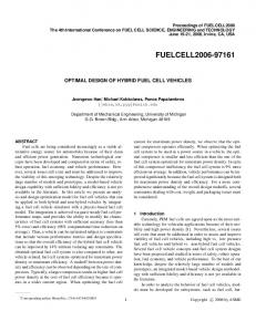
Figure-1. Hydraulic system consisting of three tanks, Source: Labvolt.
3482
VOL. 13, NO. 10, MAY 2018
ISSN 1819-6608
ARPN Journal of Engineering and Applied Sciences ©2006-2018 Asian Research Publishing Network (ARPN). All rights reserved.
www.arpnjournals.com
In the following Figure-1, we can see the schematic diagram of the hydraulic system of three coupled tanks. All tanks are identical therefore; they have the same cross sectional area S. Two cylindrical tubes with a cross-sectional area interconnect the tanks. The output flow coefficients of tank 1 and tank 2 are 𝑎 and𝑎 , respectively. The measured variables are the level of tank 1 (ℎ ), tank 2 (ℎ ) and tank 3 (ℎ ).The nominal inflow is located for tank 1 and the nominal inflow for tank 3. The control objective is to control level of tank 1 and tank 3 by manipulating the inflow rates and .Using the mass balance can be represented the following hydraulic system consisting of three tanks mediating the following equations: 𝑑ℎ = 𝑑
−
𝑎 ℎ −ℎ √
dh s a h −h √ g h −h = dt ℎ
=
−
𝑎 ℎ −ℎ √
ℎ −ℎ −s a h −h √ g h −h s
ℎ −ℎ −
𝑎 √
ℎ
(6)
Table-1. We can see the physical parameters of the hydraulic system of three tanks. Values
Maximum in-flow rate Maximum level Pipe cross- section area Pipe outflow coefficients Tank cross-section area
𝑎𝑥
= . 𝑥
−
ℎ 𝑎𝑥 = . = = = = . 𝑎 = . 𝑎 = . 𝑎 = , = .
The equations of the hydraulic system constituted by the three tanks present nonlinearities of quadratic order and the flows present in the system have linear behaviour to the square root of the level of each of the tanks.For the process of linearized equations of the robotic arm, Taylor series are used to design a state feedback controller. fa = x, u = fa x , u
+
∂f |x , u x − x ∂x
+
∂f |x , u ∂u
u−u
𝜕 | , 𝜕𝑥
𝜕
𝜕
𝑥 Being x∈ the state vector, is the input signal to the robotic arm; 𝑥 and 𝑥 are the equilibrium points, then to find and evaluate the partial derivative f (𝑥 , ) at breakeven, it is f (0, 0):
𝜕 𝜕𝑥 𝜕 𝜕𝑥 𝜕 𝜕𝑥
𝜕
| ,
𝜕 𝜕
=
𝜕 𝜕𝑥 𝜕 𝜕𝑥 𝜕 𝜕𝑥 ]
𝜕 𝜕
[𝜕 ]
The linearized state space continuous form is given in Equation: Above ẋ 𝑖 =
In the following
Parameters
𝜕 𝜕𝑥 𝜕 = 𝜕𝑥 𝜕 [𝜕𝑥
𝑥̇ [𝑥 ̇ ]= 𝑥̇ ẋ [x ̇ ]= ẋ
−
−
[
[
a
a
𝜕ℎ ̇ 𝜕ℎ
𝜕ℎ ̇ 𝜕ℎ
𝜕ℎ ̇
[𝜕ℎ
√
√
𝑥
𝜕ℎ ̇
+
𝜕ℎ
𝜕ℎ ̇ 𝜕ℎ
𝜕ℎ ̇ 𝜕ℎ
√
−
√
−[
−
𝜕ℎ ̇ 𝜕ℎ
𝜕ℎ ̇ 𝜕ℎ
𝜕ℎ ̇ 𝜕ℎ
a
− a
(√
]
a
√
𝑥 [𝑥 ] + [ 𝑥
√
+a
−
√
−√
√
−
−
√
−
model
in
]
]
)
]u t
−[
a
a
√
(√
√
−
+a
−
√
−√
)
] ]
x [x ] + x
(7)
Arrays are described above in the continuous space, to need credit in our system: 𝑥𝑘+ = 𝑥𝑘 + 𝑘 0.002 seconds. Our goal is to find a permissible control law, which minimizes the value of the second functional level costs J(u . ) =
min f ∫ [X t + QX t + u t + Ru t ]dt → u . (8)
The resulting Linear Quadratic Regulator has the following form =−
−
𝑋
(9)
where P (t) is a solution of the Riccati equation: P t = − A P t + P t A t + Ṗ t B t R− t B t P t −
With the final condition:
3483
(10)
VOL. 13, NO. 10, MAY 2018
ISSN 1819-6608
ARPN Journal of Engineering and Applied Sciences ©2006-2018 Asian Research Publishing Network (ARPN). All rights reserved.
www.arpnjournals.com
( )=
(11)
RESULTS With the data obtained by modeling the system, the system matrices were obtained in state variables and analyzed in the toolbox for Hybrid Systems of Matlab.
through the application of a generator of P.W.M. With the technique in which the work cycle of a periodic signal is modified, control is exerted on the pump.
Figure-5. Jump applied to the simulated pump in Matlab/Simulink.
Figure-2. Block diagram of the hybrid control system developed in Simulik.
In Figures 6 and 7, we can see the dynamic behavior of a system tank by using the optimal hybrid controller. It can be seen that the maximum height of the tank will be 1.3m; it has a minimum height of 0.8 m. It has an inlet flow in valve 1 of 0.5 m3 / s, starting from a height of 2.0 m.
With these results, the optimal hybrid control was implemented, obtaining the following results from the modeled system.
Figure-6. Level of the tank obtained through the simulation toolbox of hybrid systems. In Figure-7, it can be observed how the behavior of tank 2 is. It is observed that it has an initial height of 2 m, which decreases but remains at a stable level given the presence of the optimal hybrid control action. Figure-3. Hybrid systems simulated in MATLAB/ Simulink. Includes Simulink implementation and MATLAB. In Figures 4 and 5, we can see the behavior of pump 2 in front of the optimal hybrid controller with Hybrid Equations Toolbox. It can be seen that the jumps present in the pump and the behavior of the electrovalves. Figure-7. Level of the water tank with respect to the jump applied to the pump.
Figure-4. Pump status as a function of time in Matlab/Simulink. We can see that the signal that reaches the pumps has a frequency of 0.25 Hz. This frequency can vary
Labview has the optimal hydraulic system control consisting of three coupled tanks after obtaining the results in Matlab / Simulink, using the MyRIO card of the National Instrument. MyRIO is an embedded device that provides configurable inputs and outputs that allows you to design and implement various concepts with a single device. It includes analog inputs, analog outputs, digital I / O lines, LEDs, a push-button, an internal accelerometer, a Xilinx FPGA and a dual-core ARM Cortex-A9 processor. Some models also include support for Wi-Fi. Work with Labview's programming language.
3484
VOL. 13, NO. 10, MAY 2018
ISSN 1819-6608
ARPN Journal of Engineering and Applied Sciences ©2006-2018 Asian Research Publishing Network (ARPN). All rights reserved.
www.arpnjournals.com
The following figure shows the front panel implemented in Labview for the visualization of the optimal hybrid control system for the coupled tank system. It has horizontal displays that show the operator the level of each of the tanks. Likewise, control knobs are provided for the valves of the two keys present in the system.
The level sensor is used by radar, Micropilot FMR20, it has the following characteristics: Temperature: -40 to +80 ° C (-40 to +176 ° F), Pressure: -1 to +3 bar (14.5 a +43 psi), Accuracy: ± 2 mm. Likewise, the valve model 750-80-X is used as a hydraulic operation level control valve. Below is the code in Labview G language developed for the configuration of the previous devices.
Figure-11. Configuration of the instrumentation devices of the hydraulic system.
Figure-8. Front panel developed in Labview of the display hybrid control system. The following program code developed in G language shows the configuration of the tasks developed for the start of operation of the hydraulic system. The start of the electro valves, the filling of the tanks, the starting of the sensors, the communication with the embedded MyRIO system, among others.
The following graphs correspond to the level of the three coupled tanks of the hydraulic system using the optimal hybrid control. Figure-11 (a) shows the behavior of the level of tank 1 that is affected by the flow of liquid delivered by the valve or key 1, represented by the red line. (b) and (c) represent the behavior of tanks 2 and 3, respectively and (d) the position of control valve 1, with green color.
(a)
(b) Figure-9. Configurator of the starting tasks of the hybrid control system of the coupled tanks implemented in Labview. Figure-10 shows the supervisor system refers to software technology programmable in G language capable of performing the switching based on the previously implemented control algorithm.
(c)
(d) Figure-12. Configuration of the instrumentation devices of the hydraulic system. Figure-10. Part the supervisor system developed in Labview.
3485
VOL. 13, NO. 10, MAY 2018
ISSN 1819-6608
ARPN Journal of Engineering and Applied Sciences ©2006-2018 Asian Research Publishing Network (ARPN). All rights reserved.
www.arpnjournals.com
CONCLUSIONS In the development of optimal hybrid system control, the stability of the system could be guaranteed a priori using the Hamiltonian. One of the problems found in this implementation of the control was the discontinuities in the control actions that in the future could cause damage to the actuator, as a solution to this, it was proposed to tune LQR controllers for each submodel of the dynamic hybrid system and subsequently guarantee the stability of the system through the Ricatti equation. The results through the optimal hybrid system were acceptable, allowing the reduction of the discontinuities in the control signal with respect to the obtained with the Maximum Principle of Pontryagin. It can also be seen that these control signals are not saturated, which allows the system pump not to work in extreme conditions. For future work the modification of the Hamiltonian in its hybrid version is proposed, with the objective that the control to be used is an observer of states, this in order to guarantee the stability of the system a priori and the discontinuities in the actions of control can be worked through the method proposed in [11]. REFERENCES [1] Azhmyakov V., Boltyanski V. G. & Poznyak A. 2008. Optimal control of impulsive hybrid systems. Nonlinear Analysis: Hybrid Systems. 2(4): 10891097. [2] Rojas J. H. C., Serrezuela R. R., López J. A. Q. & Perdomo K. L. R. 2016. LQR hybrid approach control of a robotic arm two degrees of freedom. International Journal of Applied Engineering Research. 11(17): 9221-9228. [3] Attia S. A., Azhmyakov V. & Raisch J. 2010. On an optimization problem for a class of impulsive hybrid systems. Discrete Event Dynamic Systems. 20(2): 215-231. [4] Azhmyakov V., Rodriguez Serrezuela R., Rios Gallardo A. M. & Gerardo Vargas W. 2014. Approximations based approach to optimal control of switched dynamic systems. Mathematical Problems in Engineering. [5] Azhmyakov V., Serrezuela R. R. & Trujillo L. G. 2014, October. Approximations based optimal control design for a class of switched dynamic systems. In Industrial Electronics Society, IECON 2014-40th Annual Conference of the IEEE (pp. 90-95). IEEE. [6] Serrezuela R. R., Chavarro A. F. C., Cardozo M. A. T. & Zarta J. B. R. 2016. An Optimal Control Based
Approach to Dynamics Autonomous Vehicle. International Journal of Applied Engineering Research. 11(16): 8841-8847. [7] Serrezuela R. R., & Chavarro A. F. C. 2016. Multivariable control alternatives for the prototype tower distillation and evaporation plant. International Journal of Applied Engineering Research. 11(8): 6039-6043. [8] Aroca Trujillo J. L., Pérez-Ruiz A. & Rodriguez Serrezuela R. 2017. Generation and Control of Basic Geometric Trajectories for a Robot Manipulator Using CompactRIO®. Journal of Robotics, 2017. [9] Serrezuela R. R., Chavarro A. F., Cardozo M. A., Caicedo A. G. R. & Cabrera C. A. 2017. Audio signals processing with digital filters implementation using MyD. SP. Journal of engineering and applied sciences. 12, 1. [10] Montiel J. J. G., Serrezuela R. R., & Aranda E. A. 2017. Applied mathematics and demonstrations to the theory of optimal filters. Global Journal of Pure and Applied Mathematics. 13(2): 475-492. [11] Azhmyakov V., Martinez J. C., Poznyak A., & Serrezuela R. R. 2015, July. Optimization of a class of nonlinear switched systems with fixed-levels control inputs. In American Control Conference (ACC), 2015 (pp. 1770-1775). IEEE. [12] Perdomo E. G. & Cardozo M. A. T. 2017. A Revieew of the User Based Web Design: Usability and Information Architecture. International Journal of Applied Engineering Research. 12(21): 11685-11690. [13] Rodríguez Serrezuela R. & Carvajal Pinilla L. A. 2015. Ecological determinants of forest to the abundance of Lutzomyialongiflocosa in Tello, Colombia. International Journal of Ecology. [14] Serrezuela R. R., Sánchez N. C., Zarta J. B. R., Ardila D. L. & Salazar A. L. P. 2017. Case Study of Energy Management Model in the Threshing System for the Production of White Rice. International Journal of Applied Engineering Research. 12(19): 8245-8251. [15] Serrezuela R. R., Villar O. F., Zarta J. R. & Cuenca Y. H. 2016. The K-Exponential Matrix to solve systems of differential equations deformed. Global Journal of Pure and Applied Mathematics. 12(3): 1921-1945.
3486
VOL. 13, NO. 10, MAY 2018
ISSN 1819-6608
ARPN Journal of Engineering and Applied Sciences ©2006-2018 Asian Research Publishing Network (ARPN). All rights reserved.
www.arpnjournals.com
[16] Sánchez N. C., Serrezuela R. R., Ramos A. M. N. & Trujillo J. L. A. 2017. Real Process Characteristic Capacity Weight in the Product 500 Grams in a Rice Mill. International Journal of Applied Engineering Research. 12(21): 11588-11597. [17] Pinilla L. A. C., Serrezuela R. R., David J., Díaz S., Martínez M. F. & Benavides L. C. L. 2017. Natural Reserves of Civil Society as Strategic Ecosystems: Case Study Meremberg. International Journal of Applied Environmental Sciences. 12(6): 1203-1213.
of linear systems with piecewise constant inputs. IFAC Proceedings Volumes. 47(3): 6976-6981. [27] Poznyak A., Polyakov A. & Azhmyakov V. 2014. Robust State Feedback Control. In Attractive Ellipsoids in Robust Control (pp. 47-69). Birkhäuser, Cham. [28] Azhmyakov V., Polyakov A. & Poznyak A. 2014. Consistent approximations and variational description of some classes of sliding mode control processes. Journal of the Franklin Institute. 351(4): 1964-1981.
[18] Foroozandeh Z., Shamsi M., Azhmyakov V. & Shafiee M. 2017. A modified pseudospectral method for solving trajectory optimization problems with singular arc. Mathematical Methods in the Applied Sciences. 40(5): 1783-1793.
[29] García A. E. G., Azhmyakov V. & Basin M. V. 2014. Optimal control processes associated with a class of discontinuous control systems: applications to sliding mode dynamics. Kybernetika. 50(1): 5-18.
[19] Azhmyakov V. & Juarez R. 2017. A first-order numerical approach to switched-mode systems optimization. Nonlinear Analysis: Hybrid Systems. 25, 126-137.
[30] Poznyak A., Polyakov A. & Azhmyakov V. 2014. Attractive Ellipsoids in Sliding Mode Control. In Attractive Ellipsoids in Robust Control (pp. 163-185). Birkhäuser, Cham.
[20] Goebel R., Sanfelice R. G. & Teel A. R. 2009. Hybrid dynamical systems. IEEE Control Systems. 29(2): 2893.
[31] Poznyak A., Polyakov A. & Azhmyakov V. 2014. Mathematical Background. In Attractive Ellipsoids in Robust Control (pp. 11-45). Birkhäuser, Cham.
[21] Azhmyakov V. & Velez C. M. 2017. The singular optimal control of switched systems. In Advances in Communications and Media Research, 12: 127-143. Nova Science Publishers, Inc.
[32] Poznyak A., Polyakov A. & Azhmyakov V. 2014. Robust Stabilization of Time-Delay Systems. In Attractive Ellipsoids in Robust Control (pp. 187-223). Birkhäuser, Cham.
[22] Bonilla M., Azhmyakov V. & Malabre M. 2017. Linearization by means of Linear Implicit Rectangular Descriptions. IFAC-PapersOnLine. 50(1): 1082210827.
[33] Bonilla M., Alvarez N., Malabre M. & Azhmyakov V. 2014, June. Internal stability of a class of switched systems designed by implicit control techniques. In Control Conference (ECC), 2014 European (pp. 22542259). IEEE.
[23] Zhu X. L., Feng Z. G. & Peng J. W. 2017. Robust design of sensor fusion problem in discrete time. Journal of Industrial & Management Optimization. 13(2): 825-834. [24] Zhang C., Zhang S. & Liu Q. 2017. Homotopy method for a class of multiobjective optimization problems with equilibrium constraints. Journal of Industrial & Management Optimization. 13(1): 81-92. [25] Poznyak A. S. 2018. Dr. Alexander Semionovich Poznyak Gorbatch: Biography. In New Perspectives and Applications of Modern Control Theory (pp. 124). Springer, Cham. [26] Azhmyakov V., Basin M. & Reincke-Collon C. 2014. Optimal LQ-type switched control design for a class
[34] Aroca Trujillo J. L., Rodríguez Serrezuela R., Ramírez Zarta J. B. and Navarrete Ramos A. M. 2018. Direct and Inverse Kinematics of a Manipulator Robot of Five Degrees of Freedom Implemented in Embedded System - CompactRIO, In B. S. Ajaykumar and D. Sarkar, Advanced Engineering Research and Applications (pp. 405-419), Nueva Deli, India, Research India Publication. [35] Muñoz Calderón Y., Marín Zambrano A. M. and Rodriguez Serrezuela R. 2018. Didactic Mathematical Developments Applied to the Learning of Classic Passive Filters, In B. S. Ajaykumar and D. Sarkar, Advanced Engineering Research and Applications (pp. 420-438), Nueva Deli, India, Research India Publication.
3487
VOL. 13, NO. 10, MAY 2018
ISSN 1819-6608
ARPN Journal of Engineering and Applied Sciences ©2006-2018 Asian Research Publishing Network (ARPN). All rights reserved.
www.arpnjournals.com [36] Navarrete Ramos A. M., Aroca Trujillo J. L., Rodríguez Serrezuela R. and Ramírez Zarta J. B. 2018. A Review of the Hotel Sector in the City of Neiva and the Improvement of its Competitiveness through Quality Management Systems, In B. S. Ajaykumar and D. Sarkar, Advanced Engineering Research and Applications (pp. 439-452), Nueva Deli, India, Research India Publication.
Phytoplanktonic Community in a Neotropical Dam with Environmental Tension.
[37] Rodríguez Serrezuela R., Aroca Trujillo J. L., Navarrete Ramos A. M. and Ramírez Zarta J. B. 2018. Applications Alternatives of Multivariable Control in the Tower Distillation and Evaporation Plant, In B. S. Ajaykumar and D. Sarkar, Advanced Engineering Research and Applications (pp. 452-465), Nueva Deli, India, Research India Publication. [38] Licht Ardila D., Ramírez Zarta J. B., Navarrete Ramos A. M. and Paque Salazar A. L. 2018. Degree of Outsourcing of the Logistics Operations of a Group of Companies in the City of Neiva, In B. S. Ajaykumar and D. Sarkar, Advanced Engineering Research and Applications (pp. 466-476), Nueva Deli, India, Research India Publication. [39] Cortés Ortiz D. L., Rodriguez Serrezuela R. and Chávarro Chávarro A. F. 2018. Design and Implementation of a System of Control of Temperature and Oxygen for Tilapia Culture Pond Built on a Scale, In B. S. Ajaykumar and D. Sarkar, Advanced Engineering Research and Applications (pp. 477-493), Nueva Deli, India, Research India Publication. [40] Trujillo J. L. A., Zarta J. B. R. & Serrezuela R. R. 2018. Embedded system generating trajectories of a robot manipulator of five degrees of freedom (DOF). KnE Engineering. 3(1): 512-522. [41] Trujillo J. L. A., Serrezuela R. R., Azhmyakov V. & Zamora R. S. 2018. Kinematic Model of the Scorbot 4PC Manipulator Implemented in Matlab’s Guide. [42] Zarta J. B. R., Villar F. O., Serrezuela R. R. & Trujillo J. L. A. 2018. R-Deformed Mathematics. International Journal of Mathematical Analysis. 12(3): 121-135. [43] Losada V. A. R., Bonilla E. P., Pinilla L. A. C. & Serrezuela R. R. 2018. Removal of Chromium in Wastewater from Tanneries Applying Bioremediation with Algae, Orange Peels and Citrus Pectin. [44] Silva P. M., Yustres J. L. M., Pinilla L. A. C. & Serrezuela R. R. 2018. Structure of the
3488