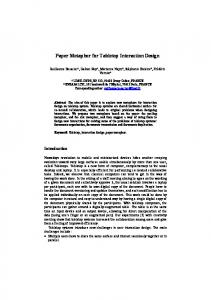
From left to right. a) a single LED puck, b) A puck. TableMouse without buttons, c) A puck shaped TableMouse, d) The full TableMouse with buttons and ID. Proc.
Proc. 11th Australasian User Interface Conference (AUIC2010), Brisbane, Australia
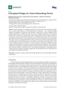
Design and Impressions of a Multi-User Tabletop Interaction Device Andrew Cunningham, Ben Close, Bruce Thomas and Peter Hutterer Wearable Computer Lab School of Computer and Information Science University of South Australia {andrew.cunningham, ben.close, bruce.thomas, peter.hutterer}@unisa.edu.au
Abstract TableMouse is a cursor manipulation device designed specifically for multiple users interacting on large tabletop surface. TableMouse tracks position, height, orientation, button state, and unique identification. It is designed using infrared light emitting diodes and computer vision to perform device tracking and identification. This paper explores the functional design of such a device. Insights into the inherent features enabled by this functionality – out of arms reach interaction, collaborative interaction – are described. The architecture, vision analysis process, and issues to consider are described. Finally two example applications utilising the TableMouse are described. Keywords: Input Devices, Tabletop Computing, CSCW.
1
Introduction
Horizontal display surfaces, tabletop displays, are a logical solution to a number of computing applications such as military (P. Hutterer, Close, & Thomas, 2006), photographic sharing (Apted, Kay, & Quigley, 2006), planning (Reitmayr, Eade, & Drummond, 2005), and entertainment (Patten, Recht, & Ishii, 2002). Proper interaction techniques and technologies are crucial for the effectiveness of these applications. Traditional desktop input technologies have been utilised with limited success to provide tabletop interaction mechanisms. Tabletop displays are suited toward absolute positioning devices which operate directly upon the display surface, while traditional input devices such as the mouse are indirect may require a separate surface to be used. Furthermore, many tabletop applications run in collaborative environments where multiple users work closely together and any interaction device should take this into consideration. The TableMouse (Figure 1) is a solution developed for multi-user tabletop interaction. The TableMouse is a visually tracked device, which is orientation independent, supports multiple devices for multiple users, is uniquely identified, and is tracked in three-dimensional space. We have previously described an experiment comparing the accuracy of the TableMouse against a traditional mouse and an eBeam pen device in a Fitts Law experiment run on a tabletop computer (Cunningham, Close, Thomas & Hutterer, 2009). The result of this experiment show the TableMouse as a suitable tabletop Copyright (c)2010, Australian Computer Society, Inc. This paper appeared at the 11th Australasian User Interface Conference (AUIC 2010), Brisbane, Australia, January 2010. Conferences in Research and Practice in Information Technology, Vol. 106. P. Calder, C. Lutteroth, Eds. Reproduction for academic, not-for profit purposes permitted provided this text is included.
Figure 1: A user with the TableMouse pointing device, especially in difficult tasks where the target is small or distant. This paper explores the unique features enabled by the design of the TableMouse. Out of reach interaction and territoriality in multi-user environments is discussed in depth. The paper describes the client-server architecture of the TableMouse system, the computer vision algorithms used and technical issues addressed.
2
BACKGROUND
As prevalent technologies such as the traditional mouse do not address the requirements of tabletop display interaction, past and current research has looked at applying a variety of solutions. Notable of these are touchscreen input, pointing based devices and tangible interaction devices.
2.1
Touchscreen Input Devices
Touchscreen technologies are an obvious choice for interaction devices for tabletop displays. Buxton et al. (1985) notes the most critical requirement of touchscreens is that “the user is not required to point with some manually held device such as a stylus or puck.” They note a number of properties that differentiate touchscreens from other mouse-like devices: 1) the number and type of events they can transmit, 2) touchscreens may support multiple points of interaction, and 3) a touchscreen device may be divided into an assortment of independent virtual devices. A severe limitation they note is the inability to signal while pointing to a touchscreen. Albinsson and Zhai (2003) note that touchscreens have two special limitations: first, the screen may become obscured by the user’s finger, hand, or arm; and second, the finger is a very low “resolution” pointing device which may adversely affect compatibility with legacy applications. Esenther and 71
CRPIT Volume 106 - User Interfaces 2010
Ryall (2006) note that the low resolution of finger input can make standard GUI widgets unusable as their size is usually optimised for the more accurate mouse pointer. Precise software-based selection techniques for touchscreens have been investigated starting with the take-off techniques (Potter, Weldon et al. 1988). Albinsson and Zhai investigated a number of possible high precision touchscreen interaction techniques which require the user to perform gross placement of the cursor near the point of selection through the initial touch, and then a second different form of interaction for the fine grain cursor positioning. Multi-touch displays allow for the extremely accurate selection on the display surface. Benko et al. (Benko, Wilson et al. 2006) investigated the following four different forms of dual finger selection: Dual Finger Offset, Dual Finger Stretch, Dual Finger XMenu, and Dual Finger Slider. They found dual finger selections increased the precision and accuracy in small target selection tasks, and in particular the increasing of the target size overcame the problem of fingertip occlusion. DiamondTouch (Dietz and Leigh 2001) is a multi-user touch input device designed to work in collaboration with a front-projection display device. The current version of the device allows for multiple touch points, and the ability to differentiate between four different users. Wu and Balakrishnan (Wu and Balakrishnan 2003) investigated the use of multiple finger and whole hand gestures with a DiamondTouch input device. These forms of interaction not only support traditional pointing, but complex command entry with concurrent direct manipulation. While DiamondTouch provides consistent unique identification, the cost of the system can be prohibitively expensive. Frustrated total internal reflection (FTIR) has been shown to provide a low-cost solution to multi-touch interaction on a tabletop display (Deutscher, Hoskinson et al. 2005 ), however it relies upon computer tracking to provide unique identification of touch locations and therefore cannot consistently uniquely identify touch locations when the user removes their hand from the table’s surface.
2.2
Tabletop Pointing Devices
There are a number of other input technologies (commercial and prototype) that have been explored for the use with tabletop displays. Guimbretière and Winograd (Guimbretiere and Winograd 2000) utilised ultrasonic EFI e-Beam pen devices to support the FlowMenu system. To support the marking menu functions an extra button had to be added to the pen device. Laser pointers (Olsen and Nielsen 2001) have been utilized as cursor control devices for large displays, where mouse button presses have been supported through various means (dwell time, strobing the laser, and an external wireless mouse button on the laser).
72
TractorBeam (Parker, Mandryk et al.) combines the natural interaction of a pen device for graphical objects within arms reach with virtual laser pointing for further objects on tabletop displays. TractorBeam is a 4DOF device (x, y, z, azimuth and elevation) utilising a topprojected display and a Polhemus Fastrak for 6-DOF tracking. TractorBeam only supports a single user and, due of the limitations of the tracking technology, the pen device must be tethered, reducing user mobility. Furthermore, metal objects in the presence of the tracker may interfere with accuracy. The Sensetable (Patten, Ishii et al. 2001) electromagnetically tracks the positions and orientations of up to ten wireless objects on a tabletop display surface. The Sensetable employs the Wacom IntuousTM sensing tablets that support 32-bit identification numbers for each mouse on the tablet. The authors state this form of technology is superior to vision based tracking as it is not susceptible to occlusion or changes in lighting conditions. A novel feature of the Intuous tablets is that tracked objects have state that can be modified by attaching physical dials and modifiers. Each tablet only supports two tracked objects natively; the Sensetable multiplexes the tracking by randomly switching the sensing coils in the tracked devices on and off. This multiplexing limits the number and performance of devices on one table; as the number of devices increases, the latency of tracking increases. A second limitation is only two devices may be moved at one time. The Sensetable was extended with the AudioPad (Patten, Recht et al. 2002), which allows for detection of rotation of the pucks and can track up to nine pucks simultaneously to an accuracy of 4mm.
2.3
Device Identification
Fiducial markers have been used to visually track objects in the physical world (Kato and Billinghurst 1999; Rekimoto and Ayatsuka 2000). The fiducial marker allows 6DOF tracking and unique identification of the individual markers. Rekimoto and Ayatsuka (Rekimoto and Ayatsuka 2000) developed CyberCode, a 2D-barcode technology as a visual tagging system. They developed their own version of tabletop phicons (physical icons), which are tangible objects that provide a means of interaction with a computer. CyberCode’s phicons track translation and orientation and are uniquely identified but do not have the notion of mouse buttons. An I/O Bulb (Underkoffler and Ishii 1998) configuration has been used tracked physical objects coded with colour dots on a table surface. This coding scheme allowed for the position, orientation, and identification of the object to be tracked. The identification is determined by the relative position of the centre dot on the object.
2.4
PuckControl
Proc. 11th Australasian User Interface Conference (AUIC2010), Brisbane, Australia
Figure 2: Four different configurations of the TableMouse. From left to right. a) a single LED puck, b) A puck TableMouse without buttons, c) A puck shaped TableMouse, d) The full TableMouse with buttons and ID The PuckControl (Takatsuka, Lowe et al. 2006) employs infrared (IR) Light Emitting Diodes (LED) as visual landmarks for a 2D translation and button activation vision based tracking system. The motivation for this device was to fill a gap between the current tabletop input devices, such as the traditional mouse, pen-based, and hand gestures. IR LEDs were employed as ambient IR levels are usually quite low in an indoor setting. Four IR LEDs are positioned on the bottom of the puck device arranged in a circle configuration. Devices are operated on top of a back-projected screen, which allows the IR LED positions to be captured by an infrared camera placed underneath the screen. Two LEDs allow for a cursor position to be calculated. The activation of one of the LEDs signals a button press from that respective mouse button thus providing the advantage of being a wireless/radio-free solution. A major benefit of PuckControl is its scalability, as many pucks can be easily supported on the tabletop surface simultaneously.
the casing of a two-button traditional mouse with custom circuitry. The custom circuit is mounted upon an insulated steel plate bracket which is attached to the front of the mouse, and positions the custom board and LEDs 30mm above buttons of the mouse. Two of the LEDs are used to indicate device state, corresponding to the mouse button clicks, and the remaining two LEDs, which are always illuminated, are used in combination with the two button LEDs to track position and orientation of the table mouse. Initially, nine LEDs were used in this device; however, visual tracking became error-prone due to the size of the board and the close proximity of the LEDs. The identification LEDs were disabled to overcome this problem. The nine-LED TableMouse requires a larger circuit board (60mm x 60mm) to be created (Figure 2c). The extra five LEDs are used to indicate a unique binary pattern for identification of devices.
3
The TableMouse is designed to be both a graphical user interface (GUI) pointing device and a tangible interaction device supporting a wide range of tabletop configurations and software. The software layer of the TableMouse consists of 1) a server backend performing the image processing and messaging of TableMouse events to registered client applications and 2) an optional client framework. The TableMouse supports most tabletop configurations and legacy applications currently available. At its most basic configuration, TableMouse can be used as a single operating system cursor device. This provides the TableMouse the ability to seamlessly interact with legacy applications while maintaining orientation independence. Under Linux with MPX (described below) TableMouse can support multiple pointing devices at a system level and therefore integrates multiple cursor support for legacy applications. Finally, custom applications that support multiple cursors with 4DOF information can use the TableMouse client framework to subscribe and interpret TableMouse server events into unique device information, making use of the full capabilities of the TableMouse.
TableMouse
The TableMouse is a visually tracked device based on a unique arrangement of up to 9 infrared LEDs, providing position, elevation, orientation, button state and unique identification. We take a computer vision approach as it allows devices to be operated untethered, is not affected by interference and can handle a large number of simultaneously tracked devices. We imagined two different form factors for the TableMouse; a puck-like device to act as a tangible prop, and a mouse-like device to interact with a traditional graphical user interface system. Four configurations have been prototyped (Figure 2), three of which have the puck form factor, while the last is based on a modified traditional mouse. The exact feature set available to each configuration is defined by the number of active LEDs on the device. A single LED configuration (Figure 2a) conveys only two-dimensional position. A 4 LED configuration (Figure 2b) conveys two-dimensional position, height and orientation, while a nine LED configuration (Figure 2c) has the complete feature set. The mouse-like TableMouse (Figure 2d) is our most successful configuration from a usability and acceptance point of view. It is a 4LED configuration, consisting of
3.1
Functionality
73
CRPIT Volume 106 - User Interfaces 2010
Figure 3: Device Orientation Figure 4: TableMouse Projection
3.1.1
Orientation independence
As an absolute positioning device, the TableMouse is orientation independent from the display, letting users operate the device from any edge of the screen.
3.1.2
4 Degrees of Freedom
Being a visually tracked device allows the TableMouse to perform 4DOF tracking (x, y, z, and θ) in real time. Orientation (θ) is calculated in 1D around the camera’s view direction.
3.1.3
TableMouse as a pointing device
3.2.1
Device Height
Although the TableMouse physically resembles a traditional mouse, it isn’t restricted to the tabletop surface. From our experiments, however, we have found that people instinctively use it on the tabletop surface, most likely due to its familiar traditional mouse form factor. Given this default behaviour, we experimented with using the device height for secondary functionality. We felt that secondary functionality usually reflects advancement in the user’s knowledge of the system, and this in-turn is reflected by the advanced usage of the TableMouse. As an initial test, we use device elevation to simulate the scroll wheel functionality of a traditional mouse. When the table mouse was elevated above the tabletop and the right-button held down, a scroll event would be sent to the application current application, allowing users to scroll long documents or pan through an image, for example. This scroll event, being the delta (Sx,Sy) from the current position of the active application’s viewport, is defined as follows:
The TableMouse can operate as a normal Microsoft Windows, X Windows or MacOS X mouse device. To perform this, a client application called Squeak listens for TableMouse events and propagates them back to the underlying operating system as native system cursor and button calls. This allows the TableMouse to be used with all legacy applications that are not natively aware of the TableMouse. Specialised applications can use the TableMouse client application framework to subscribe to the same events as Squeak to determine the orientation and height of the (Sx,Sy) = (Ddx •Dh • k), (Ddy •Dh • k) device controlling the system cursor. This allows a user to € the seamlessly work with legacy applications, where TableMouse would operate as a traditional 2DOF mouse, Where Ddx , Ddy are the delta of the horizontal and and TableMouse aware applications, where the device vertical TableMouse movements, respectively, Dh is the € of the device from the table’s surface and k is would have the full 4DOF support. Such functionality is height essential for a tabletop device as this reduces cognitive some scaling constant. context switching that would otherwise occur when € This€ allows a user to fluidly scroll, overcoming the € continuous or changing from legacy applications to custom TableMouse’s inability to have any applications. Having two different physical input devices analogue buttons such as a scroll wheel. € for each set of applications would require the user to 3.2.2 Device Orientation switch devices. To improve usability when operated from an orientation 3.1.4 Unique Identification that is not aligned with the system orientation, the Each TableMouse may be uniquely identified through a TableMouse positions the system cursor in-front of and orientated with the particular device (Figure 3). This binary pattern of the fixed IR LEDs. feature is also crucial to ensure the user can aim with the cursor as it renders it always visible. 3.1.5 Multiple pointer support The TableMouse has support for up to 16 devices operating as 16 independent X Windows system cursors. To achieve this, TableMouse integrates with MPX (Hutterer and Thomas 2007), a windowing system that natively supports Single Display Groupware features.
3.2
Features
We have identified and explored several features that emerge from the functionality of the TableMouse.
74
3.2.3
Out of Arms Reach Interaction
While we are primarily interested in investigating an absolute positioning device, being able to interact with parts of the display which are out-of-reach, similar to the pointing feature of TractorBeam (Parker, Mandryk et al. 2005), is desirable. As a by-product of the top-down camera configuration, the TableMouse can operate as an absolute-positing device or as a scaled positioningdevice, where absolute movements of the device are
Proc. 11th Australasian User Interface Conference (AUIC2010), Brisbane, Australia
scaled on to display. When operated exclusively on the tabletop surface there is a one-to-one mapping between the cursor position and the position of the device on the display. As the device is raised above the table’s surface however, the cross section of the capturing camera’s view frustum is reduced and movements of the device are scaled relative to the device’s height from the table. This property allows the user to manipulate cursors in a larger display area than their arm’s reach is capable of, as depicted in Figure 4. The black rectangles in the figure indicate positions of TableMouse devices. By raising the device from the tabletop surface the user is able to interact with the far end of the display thus reducing the user fatigue that can occur when they are required to physically reach across the table. Comparatively, go-go interaction techniques (Poupyrev, 1996) can confuse a user. These techniques provide a linear mapping up to an arbitrary point, beyond which a non-linear mapping is used. Confusion occurs since predicting from which point a non-linear mapping occurs and the function used is difficult without any cue. The TableMouse relies upon the implicit projective nature of the device to perform out-of-reach interaction. This is intuitive as it replicates the interaction a shadow would have if the top mounted camera were a light source. Through user study feedback, we have found this unique out-of-arms-reach interaction to be a beneficial attribute of the technology. One user commented positively that in certain cases the device was less strenuous than the e-Beam. This was especially obvious in cases where the user was not tall enough to comfortably reach the end of the table. Based on this feedback we have implemented a “scaling” property into the TableMouse software, allowing the out-of-arms reach to be exaggerated on a per-user basis. Out of arms reach interaction is of interest to the territories (Stacey, Sheelagh et al. 2004) that occur naturally in collocated collaboration. Users collaborating on a tabletop have tendencies to partition the available space into personal, group and shared territories. Personal territories are established closest to the user for ergonomic reasons, under which case it would be preferential to use the TableMouse exclusively on the tabletop to stabilize the hand for better accuracy. Group territories represent shared space between all users and tend to be located in a position optimal for all those involved. In this case, the out-of-reach interaction would be preferential as the user could reach further into the group territory without having to relocate. This also serves as a social cue to indicate when interaction with a group territory is occurring. Collisions in group territories may be avoided since users can “hover” the TableMouse above the other users, an aspect which just is not possible with many touchscreen and pen-based interactions. Furthermore, since the elevation of the device is tracked, when a user positions their TableMouse to cover another TableMouse, a client application could employ an artificial “veto” function – the social cue of covering up another user’s device may be recognized and enforced by the software.
Figure 5: System Diagram
3.3
Vision Analysis
The image processing side of the server is built upon the open source OpenCV image processing library. Images are captured from an IEEE1394 camera at 30 frames-persecond (FPS) at a resolution of 1024x768, in 8bit mono. The camera has an IR bypass filter installed over the lens allowing the infrared near and medium light (750nm – 2000nm) to pass through to the camera. We chose a binary pattern of fixed IR LEDs to represent the unique position and identification of each TableMouse. We rejected a blinking binary pattern for identification due to latency in determining the identification pattern. As Moore et al. (Moore, Want, Harrison, Gujar, & Fishkin, 1999) note, the theoretical throughput for detecting a pattern is one half the framerate of the digital camera observing the pattern. Given that we are trying to use common components (such as a 30 FPS camera), this option just isn’t sufficient.
3.3.1
Development Issues
Before discussing the vision analysis process, it is worth mentioning several issues that should be noted to anyone developing similar technology to the TableMouse. Issue 1. LED divergence. The LEDs used have a light distribution that is restricted to a low divergence. Low divergence becomes a problem when the beam of light produced by the LED does not enter the camera field-ofview (FOV) because the LED is angled away from the FOV of the camera. This can be addressed by increasing the intensity of the LED, however this creates a flood of light when the LED directly points into the camera. These are diametric issues; increase the LED brightness too much and it will flood the camera image when it is incident with the camera, don’t increase the brightness and it will not be visible when angled away from the camera. Issue 2. Rapid movement causes LEDs captured by the camera can appear smeared. In the worst case, the LEDs will appear to blend into each other. Issue 3. Accuracy is a major objective of the TableMouse. In our experimental setup, where the 75
CRPIT Volume 106 - User Interfaces 2010
camera is mounted 1.5 meters above the table, we capture more than the full screen surface in the camera image. This means that some of the image resolution is beyond screen space, effectively reducing the number of useful image pixels. From where our camera is mounted, approximately 720 x 534 of the 1024 x 768 image is used by the screen surface; almost a 30% reduction. Several solutions were employed to address these issues in the vision analysis process (Figure 5), which is described in the following sections.
3.3.2
Camera Image Undistortion
Initially in the vision analysis, an image is captured from the camera and processed through the Camera Coordinate Transformer, which applies a homography to the image to correct for the radial and tangential distortion of the camera as well as mapping coordinates in the image into 2D screen space.
3.3.3
Particle Recognizer
The corrected image is passed to the Particle Recognizer, which captures “particles” in the image. In this case, particles are LEDs, however any sort of distinguishable point may be considered a particle, hence the generalised term of “particles”. This allows us to adapt the TableMouse vision analysis to alternate technologies to IR LEDs and cameras. The Particle Recognizer begins by thresholding the image to remove any low-level noise. Through experimentation, we settled on an adaptive thresholding, which performs a threshold on the pixel T(x, y) against a Gaussian averaged n-by-n region around the pixel. We chose this method as this produced the best results to address Issue 1, which causes the LEDs near the periphery of the camera to appear far less lit than those in the centre. After thresholding, the particle recognizer identifies all contours within the image. To compute the centre of mass of the detected contours, which is required to determine the exact device location, we use the contour moments. This decision was made following experimentation to increase the pixel accuracy of the TableMouse (Issue 3). To compute the centre, we find the zeroth and first moments: n
∑ x=
n
i= 0 n
3.3.4
i
,y =
i
i= 0 n
∑ I (x , y )
∑ I (x , y )
i= 0
i= 0
i
Where x and the contour. €
∑ I (x , y )y
I (xi, yi)x
i
i
i
TableMouse without requiring expensive code rewrites, as the graphs could be specified in an easily rewritable configuration file. Eventually, an optimal device layout was determined (Figure 6) based on tracking accuracy in most common circumstances. At this stage the generalized graph matching algorithm was replaced with an optimized discreet syntactic pattern recogniser (Schalkoff 1992), that attempts to match relative distances between sets of particles with a set of known constraints. These constraints are split into required structural constraints and secondary state and identification constraints. Required structural constraints identify the particles that must be present on the device, otherwise a device’s position and orientation cannot be determined. These constraints and related margins of error provide optimal tracking under normal operation without resulting in erroneous devices being identified, as specified in Table 1. These constraints allow for some margin of error as the camera introduces noise into the data. Furthermore, if the user were to tilt the device, the angles and relative distances would vary from the ideal state, which the margin of error to compensates for. Description
Margin of error
1
A and B are the closest particles to each other
N/A
2
C is closer to A than to B
N/A
3
|AC| ≈ |AB| * 1.5
|AB| * 0.05
4
|BC| ≈ |AB| * 2.5
|AB| * 0.05
5
∠BAC ≈ ±0.75π rad
0.05
Condition
Table 1: Constraints The computer vision algorithms were chosen to be computationally inexpensive, as we wanted to rapidly prototype a variety of device designs and functionality without relying on any hardware vision processing. The final algorithm returns a list of devices P, where each device is defined as: pi = (xi, yi,zi,θi,ℑi,εi) Where x i and y i are the coordinates of the device, z i is the height, θ is the orientation, ℑi is the set of button state and εi is the unique identification. Besides the € coordinates, any of these values may be null, indicating € that the € device does not support that particular€feature. € Given this definition€of the device, the following € parameters are used in the vision analysis process:
y are the computed sub-pixel centre of
Device Recognizer
€These€particles
are passed to the Device Recognizer. During initial development, device recognition occurred through graph matching, which attempts to match an ideal template graph to a set of input graphs. In this case, the graphs were specified as particles being vertices of the graph, and the edges being physical relationships between the vertices (e.g., vertex N should twice as far from vertex M as vertex O). This choice was essential in allowing us to rapidly prototype the physical layout of the
76
Figure 6: Device Layout
Proc. 11th Australasian User Interface Conference (AUIC2010), Brisbane, Australia
V := {v0, v1 … vn}, where each vi is an identified particle of the form (x, y) V’ := set of particles in V that are recognised as forming a device, initially Ø D := (dij)n×n is a n × n symmetric matrix, where dij is equal to the distance between the particles vi and vj (||vi – vj||) E := (eij)n×n is an n × n matrix where for any row in E, ei,1…n = argsort(ai,1…n) and argsort is a function that returns the indices of its sorted argument values. P := {p0, p1 … pm}, set of identified devices, initially Ø, m is the number of identified devices. Q := set of particle secondary constraints specified as tuples of the form (β, dx, dε, ax, aε), where β represents which particle, either state or unique identification, this constraint specifies (one of D…I), dx represents the ratio |AB|:|A β|, dε represents the acceptable distance error, ax represents the angle BAβ and aε is the acceptable angle error Pre-computing D and E allows the classification to be run as a linear search through the set V, as shown here: Algorithm 1: DOCLASSIFY for i from 0 to |V| comment: only process particles that do not already form another device if v ∉ V’: result = CLASSIFY(i, D, V) if result ≠ Nothing V’ ← V’ + result The classify function performs constraint matching against the particles in V in an attempt to determine if and vi corresponds to LED A of a unique device. The function can be divided into two parts. The first part attempts to match the required structural constraints as a series of assertions. If one assertion fails, the function terminates returning nothing: Algorithm 2: CLASSIFY(i, D, V) output: Nothing if Vi is not LED A of a device, else comment: copy the indices of the 3 closest particles to Vi into a, b and c, and copy the coordinates of the 3 closest particles in A, B and C a,b,c ← Di,0, Di,1, Di,2 A,B,C ← Va, Vb, Vc
if ∠BAC ≠ -2.8c ± 0.5c then return ( Nothing ) comment: We have recognized a device At this stage, classify has recognized a device via the required structural constraints, with its centre located at A, and an orientation determined by AB. The second part of the classify function uses secondary state and identification constraints to recognise the identification and state particles of the device. Since A, B and C are known, the identification and state LEDs of the device can be recognised by a linear search through the next 6 adjacent LEDs to A. So for any η in Di,i+3…i+9, this search will attempt to match the characteristics specified in the set of tuples Q against the ratio |AB|:|Aη| and ∠BAη. This determines if any of the LEDs match the state particle D or identification particles {E F G H I}. Any recognised identification LEDs are placed into a bit set which corresponds to the unique identity of the device. The function finally returns identified device, which is appended to P.
3.3.5
Device Tracking
The identified devices, referred to as “device samples”, are passed to the Device Tracker. The purpose of the Device Tracker is to assign a consistent unique identification to successive samples (known as assigning a device track to a device sample). This unique identification may either be persistent, which is based upon the identification LEDs on the device, or transient, for devices without identification LEDs. In the persistent case, the tracker is used to enforce or correct the syntactic classification. In the transient case, the tracker assigns an arbitrary unique identification that exists only as long as the device is present on the interaction surface. The Device Tracker is currently implemented with the transportation algorithm, which was chosen for it is low processor usage while still providing stable tracking. The algorithm attempts to minimize the cost of assigning a previously identified device (referred to as a track) and devices recognized in the current frame (referred to as samples). The cost is determined by a cost function, which applies a set of heuristics to a track and a sample, and may be described as: Γ(T ) COST = Spos − Tpos + Tv + 360 Where Spos and Tpos are the position of the sample and the track respectively, Tv is the velocity of the track as
€
€
€
€
comment: C must be closer to A than to B if |AC| > |BC| then return ( Nothing ) comment: |AC| must be within 1.5 • |AB| if |AC| is not ≈ |AB| * 1.5 or |BC| ≈ |AB| * 2.5: then return ( Nothing ) comment: The angle ∠BAC must be within -2.8c
Figure 7: Server Architecture
77
CRPIT Volume 106 - User Interfaces 2010
4.1
Figure 8: CheeseDraw computed from previous matching tracks. Γ is a function that returns the number of milliseconds that have elapsed since the last observation of its argument. This cost function is minimized across all tracks and samples to € perform tracking.
4
Server-Client Architecture
TableMouse is designed as TCP/IP client-server framework. The server performs the image processing and vision analysis and distributes the identified devices as events to subscribed clients. While this approach does introduce latency into the system, we chose a clientserver architecture as this is the most flexible in terms of writing client applications as most languages have a TCP/IP stack – currently there are TableMouse client stacks for C++, Java, and Python. Basic TableMouse system interaction can occur by running the client program, Squeak. Squeak manipulates the standard operating system mouse pointer using the position and state of the first device returned by the TableMouse server. Specialised applications can use the TableMouse client application framework to subscribe to the same events as Squeak to determine the orientation and height of the device controlling the system cursor. This architecture is illustrated in Figure 7. This allows a user to seamlessly work with legacy applications, where the TableMouse would operate as a traditional 2DOF mouse, and TableMouse aware applications, where the device would have the full 4DOF support. Such functionality is essential for a tabletop device as reduces the effect of the cognitive context switch that would otherwise occur when switching from legacy applications to custom applications while using the TableMouse.
Figure 9: A rotation in CheeseDraw
78
Applications
We developed two notable applications that take advantage of the TableMouse; CheeseDraw and MalaMinya. CheeseDraw is a vector-based drawing application that demonstrates the rich interactions possible enabled by the TableMouse. CheeseDraw leverages the 4DOF nature of the TableMouse to create, manipulate and delete graphical objects on a canvas. CheeseDraw appears as a standard GUI application with a minimal interface (Figure 8). The left side of the window contains controls for the user to select the type of vector shape they will create, including rectangles, ellipses and photographs. The process of creating vector shapes resembles most drawing applications, requiring the user to click and drag regions on the canvas with the TableMouse to specify position and size of the new shape. Once created, the user may manipulate the shapes using the full capabilities of the TableMouse. Clicking and dragging a shape will translate the position of the shape around the canvas. One-degree orientation of the TableMouse is directly reflected in the dragged shape so that the orientation of the TableMouse affects the orientation of the shape in a one-to-one mapping (Figure 9). Raising the TableMouse from the table surface while dragging a shape causes the shape to scale respective to the elevation of the device from the table. This unique interaction allows a user to alter three attributes of a shape (position, orientation and scale) of a shape in one continuous motion of the TableMouse Our multi-user drawing tool MalaMinya (not pictured) utilises SDG functionality to provide a drawing canvas that can be operated by use to eight users simultaneously. Figure 5 shows MalaMinya begin operated by three different users. The users have unique icons assigned to their cursors and can draw lines, delete with an eraser or wipe the whole canvas. Initiating a tool only activates the tool for the activating device. Toolbars are aligned around the table for close proximity to the user’s physical position, and each user has their own toolbar. The user’s toolbar is identified by the user’s unique cursor icon. This is indicated on the left side of the user’s tool bar. The toolbars are limited to a single user each using MPX’s floor-control mechanism, whereas the various colour buttons are accessible for anyone. The available colours are spread around the drawing canvas and each user can pick a colour at any time. Doing so only changes colours for the user’s device. MPX allows MalaMinya to be used simultaneously with legacy applications such as a web browser or office applications.
5
Discussion
We have received extensive subjective feedback from a previous user study (Cunningham et al. 2009). Consistently, users have commented that the TableMouse feels “smooth” and “fluid”, despite the fact that the device is limited to the camera’s frame-rate of 30fps. We believe this perceived smoothness is due to the TableMouse being unrestricted to any surface, unlike a traditional mouse where lifting it from its surface will stop the tracking, causing a discontinuity between the
Proc. 11th Australasian User Interface Conference (AUIC2010), Brisbane, Australia
cursor and the physical device. This theory is enforced by user comments repeatedly mentioning that they appreciated being able to lift the device from the table while still controlling the cursor. Users have found it disconcerting that under rapid movement the cursor would trail behind the mouse. This is a technical limitation between the time of moving the mouse and processing the captured frames from the camera to move the cursor. However, we feel that this issue is acceptable given the benefits of the approach we have taken. The TableMouse requires more physical prototyping. The most successful design, based on the traditional mouse, carries with it an incorrect intuition of how the device should be used; it can still be utilised above the tabletop. This would be addressed by a more unique form factor and instruction.
6
Conclusion and Future work
We have detailed the design and implementation of a multi-user tabletop interaction device. We have discussed the features that are enabled by this implementation. The concepts of out-of-reach interaction and territoriality, upon further exploration, may prove to be boons to multiuser collaboration. We also discussed the issues and solutions we came upon when implementing the TableMouse and its computer vision algorithms, which would prove useful to anyone researching a similar technology. There are a number of future research directions we would like to pursue. Firstly, we plan to write more client applications to leverage the concepts of territoriality and out of reach interaction. To improve the feel of the device, we will look at incorporating some physical features of a pen-like device to encourage it to be lifted above the tabletop surface and we will experiment with multiple camera tracking to provide full 6DOF tracking of the TableMouse, as we envision tilt gestures to be a useful interaction technique.
7
References
Albinsson, P. and S. Zhai (2003). High precision touch screen interaction. Proc. of the ACM SIGCHI conference, Ft. Lauderdale, ACM Press. Benko, H., A. D. Wilson, et al. (2006). Precise selection techniques for multi-touch screens. Proc. of the ACM SIGCHI conference, Montreal, Quebec, Canada. Buxton, W., R. Hill, et al. (1985). Issues and techniques in touch-sensitive tablet input. Proc. of the 12th annual conference on computer graphics and interactive techniques, ACM Press. Cunningham, A., Close, B., Thomas, B., and Hutterer, P. (2009). “TableMouse: A Novel Multiuser Tabletop Pointing Device” to appear in 21st Annual Conference of the Australian Computer-Human Interaction Special Interest Group (CHISIG) of the Human Factors and Ergonomics Society of Australia (HFESA). Deutscher, M., R. Hoskinson, et al. (2005 ). Echology: an interactive spatial sound and video artwork http://doi.acm.org/10.1145/1101149.1101347 Proceedings of the 13th annual ACM international
conference on Multimedia Hilton, Singapore ACM Press: 937-945 Dietz, P. and D. Leigh (2001). DiamondTouch: a multiuser touch technology. Proc. 14th ACM symposium on User interface software and technology, Orlando. Esenther, A. and K. Ryall (2006 ). Fluid DTMouse: better mouse support for touch-based interactions Proceedings of the working conference on Advanced visual interfaces Venezia, Italy 112-115 Guimbretiere, F. and T. Winograd (2000). FlowMenu: combining command, text, and data entry. Proc. 13th ACM symposium on User interface software and technology, San Diego, CA. Hutterer, P. and B. H. Thomas (2007). Groupware Support in the Windowing System. Eighth Australasian User Interface Conference (AUIC2007), Ballarat, Australia. Kato, H. and M. Billinghurst (1999). Marker Tracking and HMD Calibration for a Video-based Augmented Reality Conferencing System. Proc. 2nd IEEE and ACM International Workshop on Augmented Reality '99, San Francisco, CA. Olsen, D. R. and T. Nielsen (2001). Laser pointer interaction. Proc. ACM SIGCHI conference, Seattle. Parker, J. K., R. L. Mandryk, et al. (2005). TractorBeam: seamless integration of local and remote pointing for tabletop displays. Proc. of the 2005 conference on Graphics interface, Victoria, BC, Can. HC Comm. Soc. Patten, J., H. Ishii, et al. (2001). Sensetable: a wireless object tracking platform for tangible user interfaces. Proc. ACM SIGCHI conference, Seattle. Patten, J., B. Recht, et al. (2002). Audiopad: A Tag-based Interface for Musical Performance. NIME 02, Dublin. Potter, R. L., L. J. Weldon, et al. (1988). Improving the accuracy of touch screens: an experimental evaluation of three strategies. Proc. ACM SIGCHI conference, Washington, D.C. Rekimoto, J. and Y. Ayatsuka (2000). CyberCode: designing augmented reality environments with visual tags. Proc. DARE 2000, Elsinore, Denmark. Schalkoff, R. (1992). Pattern recognition - statistical, structural and neural approaches, John Wiley & sons. Stacey, D. S., M. Sheelagh, et al. (2004). Territoriality in collaborative tabletop workspaces. Proceedings of the 2004 ACM conference on Computer supported cooperative work. Chicago, Illinois, USA, ACM Press. Takatsuka, M., N. Lowe, et al. (2006). TR #595: PuckControl: A Computer Vision-based Wireless Input Device for Tabletop Display, School of Information Technologies, Uni. of Sydney. Underkoffler, J. and H. Ishii (1998). Illuminating Light: An Optical Design Tool with a Luminous-Tangible Interface. Proc. ACM CHI 98 conference, Los Angeles. Wu, M. and R. Balakrishnan (2003). Multi-finger and whole hand gestural interaction techniques for multiuser tabletop displays. Proc. 16th ACM symposium on User interface software and technology, Vancouver.
79