IEEE TRANSACTIONS ON MAGNETICS, VOL. 48, NO. 11, NOVEMBER 2012
3999
Design and Instrumentation of an Advanced Magnetocaloric Direct Temperature Measurement System Mohammadreza Ghahremani, Yi Jin, Lawrence H. Bennett, Edward Della Torre, Hatem ElBidweihy, and Shuo Gu Dept. of Electrical and Computer Engineering, George Washington University, Washington, DC 20052 USA The magnetocaloric temperature change is an important factor in the performance evaluation of the magnetocaloric material’s magnetocaloric effect (MCE), which has been attracting significant interest due to its application in energy efficient near-room temperature magnetic refrigeration technology with environmentally desirable characteristics. A novel magnetocaloric temperature change test system with fully controlled field, temperature, and time capabilities is designed and analyzed. This test system allows the detailed observations of the applied field effect, sample temperature effect, and time effect on the testing magnetocaloric material. The effectiveness of this test system was evaluated by testing the MCE within sample of Gd turnings. The magnetocaloric temperature change measurements, , at various H and Temp was measured and showed numerical and characteristic agreements with literature, thus provided evidence that this test is capable of making conventional measurement as well as new measurements on the material’s dynamic time effects. Index Terms—Gadolinium, magnetocaloric effect (MCE), magnetic refrigeration, magnetocaloric temperature and MCE rate.
I. INTRODUCTION
M
AGNETIC refrigeration is an emerging energy efficient and environmentally friendly refrigeration technology with the following desirable design characteristics: (i) it does not use ozone depleting chemicals (CFCs), hazardous chemicals (NH ) or greenhouse gases (HCFCs and HFCs) [1]; (ii) the cooling efficiency of magnetic refrigeration is significantly higher than compressor-based techniques, e.g., the cooling efficiency in magnetic refrigerator working with gadolinium has been shown to reach 60% of the theoretical limit compared with only about 40% in the best gas-compression refrigerators; and (iii) the magnetic refrigerator can be built more compactly and generates much less noise [1], [2]. With the push for the commercialization of the magnetic refrigerator, it is vitally important to perform evaluation of the magnetocaloric effect (MCE) of suitable magnetic refrigerants; in particular, recent study of dynamic time effects, i.e., magnetic sweep rates, is creating a growing interest on the time dynamics of magnetocaloric materials [3], [4]. Previous studies of magnetic refrigeration generally focused on the properties of high magnetocaloric materials [5], [6], and the instrumentation of different magnetocaloric effect measurement methods [7]. Magnetocaloric effect can be measured by indirect measurements such as magnetization method and calorimetric method [8], or direct measurement [9]. In this work we studied magnetocaloric effect by direct measurement. This paper presents the design and instrumentation of an advanced magnetocaloric temperature change test system with fully controlled time, ambient temperature and external field capabilities based on the apparatus designed by Shir [10]. The effectiveness of this system is tested by measuring the MCE properties of a sample of gadolinium turnings at various sample Manuscript received February 27, 2012; revised May 09, 2012; accepted May 25, 2012. Date of current version October 19, 2012. Corresponding author: M. Ghahremani (e-mail:
[email protected]). Color versions of one or more of the figures in this paper are available online at http://ieeexplore.ieee.org. Digital Object Identifier 10.1109/TMAG.2012.2203108
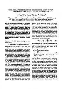
Fig. 1. Design Schematic of the Advance Magnetocaloric Direct Temperature Test System.
temperatures with applied field increasing from 0 T to 2 T. In the sample of gadolinium turnings, each piece of turning is small enough, 3 mm 1 mm 0.5 m, so we can conclude that heat distribution should be same in entire sample. II. SYSTEM INSTRUMENTATION In order to measure the magnetocaloric temperature change of magnetic materials as a function of temperature, time, and external applied field, an advanced measurement apparatus was designed and configured to allow full automatic remote control. The principle schematic of the system set-up is shown in Fig. 1 and the picture of the advanced magnetocaloric temperature change test system is show in Fig. 2. The difference between this system and Shir’s system is the inclusion of more components and equipment in order to control the temperature and the rate of change of the magnetic field. This system consists of six major components. Shir described (i) the permanent Halbach magnet to provide a magnetic field ranging from 0 T to 2 T and (ii) Cernox temperature sensors. The new components are (iii) a temperature bath circulator that circulates temperature controlled liquid (e.g., SIL 180 silicon oil) from the bath into (iv) a two concentric glass tubes, shown in Fig. 1, that transfers temperature from the bath circulator to the refrigerant bed, and (v) controllers to read the sample’s direct
0018-9464/$31.00 © 2012 IEEE
4000
IEEE TRANSACTIONS ON MAGNETICS, VOL. 48, NO. 11, NOVEMBER 2012
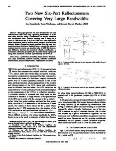
Fig. 3. Front panel of the control system program written using LabVIEW. The program has capabilities of controlling and synchronizing system components. Fig. 2. Picture of the Advanced Magnetocaloric Direct Temperature Test System.
temperature, and (vi) a data acquisition, control, and synchronization program written using LabVIEW software, which allows automatic remote command of the major components and recording the data, followed by analysis of the measured system data. A. Two Concentric Glass Tubes The motivation behind the design of the two concentric glass tubes is to find a solution to set the refrigerant bed ambient temperature to the desired temperature. The two concentric glass tubes consists of combining two glass tubes with different diameters where the inner tube is 18 mm in diameter and the outer tube is 25 mm in diameter. The magnetocaloric magnetic sample is positioned inside the inner tube. The space between the two tubes, i.e., the channel inside the outer tube and outside of the inner tube, forms a liquid channel with width of 2 mm. This channel permits the flow of the controlled temperature from the circulator. Over time, the controlled temperature permeates throughout the two concentric glass tubes and sets the temperature of the sample. B. Temperature Sensing Using Cernox Sensors The direct measurement of the temperature of the magnetocaloric sample is obtained by the Cernox temperature sensor from Lakeshore. Cernox sensor was selected over thermocouple sensors because of its low magnetic field-induced errors over the 0.3 K to 420 K temperature range with accuracy of 0.001 K and time resolution of 1 ms. In addition, the Cernox sensor offers high sensitivity and negative temperature coefficient resistance temperature detector. One of the advantages of this system compared to previous magnetocaloric temperature measurement systems [11], [12] is the use of thermistor based temperature sensors, Cernox, instead of thermocouples, because alternating magnetic fields affect thermocouple based temperature sensors and cause errors in the recorded temperature [13], while Cernox sensors can be used in alternating magnetic fields. The Cernox magneto-resistance is typically negligible above 30 K and is not significantly affected by orientation relative to the magnetic field.
C. Control System The system control program was written with LabVIEW software. The program allows remote control and synchronization of the test system components and gathers measured signals from the temperature sensors, which are then evaluated and analyzed. By using this program, the applied magnetic field can be set between 0 T to 2 T in intervals of 1 mT, the sample’s ambient temperature can be set between ( C or 233.15 K to 200 C or 473.15 K) with accuracy of 0.01 C or 0.01 K; and the time is set in intervals of 0.1 s. The front panel of the control system program is shown in Fig. 3. In the upper-left side of the panel, the communication protocol between main program and system components control unit (permanent magnets, cylinder displacer, temperature sensor and LabVIEW interface) are defined. In the upper-right side of the panel, the permanent magnet (Halbach) parameters are defined such as sample field value and sweep rate. The magnetic field value can be set between 0 T–2 T with an accuracy of 1 mT and the sweep rate can be set from 20 mT/s to 2 T/s. The lower part of the panel shows measured temperature by sensors and has the capability to display and record temperatures from two Cernox sensors and two thermocouples simultaneously. The vertical axis of the chart is temperature and the horizontal axis is time. The whole functional cycle of this system consists of: 1. Control System Program sets the refrigerant circulator temperature to the defined test temperature. 2. Circulator changes the liquid temperature to the programmed temperature and circulates this liquid to the liquid channel between the two concentric glass tubes. 3. The temperature of the liquid channel permeates over time through the entire glass tube, thus setting the temperature of the sample to the programmed temperature. 4. The permanent magnet applies a magnetic field from 0 T to 2 T to the sample. 5. Temperature sensor measures the sample temperature with accuracy of 0.001 K and a rate of 10 pts/s and sends this data to Control System Program. 6. Control System Program gathers the measured direct temperature from sensor. After a programmed waiting period, the cycle is repeated using the next defined temperature.
GHAHREMANI et al.: DESIGN AND INSTRUMENTATION OF AN ADVANCED MAGNETOCALORIC DIRECT TEMPERATURE
Fig. 4. 3D surface plot of Gadolinium curve, as a function of Sample Temperature, Time and Applied Field. The Sample Temperature ranges from 285 K to 301 K, the time ranges from 0 s to 40 s, and applied field increases from 0 T to 2 T. The dotted blue line shows the experimental data from 0 K (shaded in points. The contour plot shows the transition of K (shaded in purple). red) to maximum change
4001
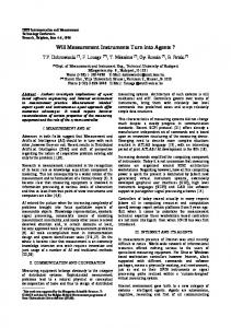
Fig. 6. Rate of MCE Temperature Change for Gd turnings samples. The straight lines are for the direct temperature change results (Left Y-Axis). The circular lines are the rate of temperature change results (Right Y-Axis).
cently reported pure Gd direct measurement results [11]. The shape of the curve is similar to literature [16] but the measurement from this new test bed reveals a clear deviation as the sample transitions from 285 K to 293 K, similar to evidence previously shown at high fields [14]. In addition to making conventional magnetocaloric thermal temperature measurements, this test system has the capability of calculating the rate of MCE temperature change, as seen in Fig. 6 for the Gd turning sample. The rate of MCE temperature change is defined as the differential change in magnetocaloric effect as a function of time. Based on these new experimental results, the maximum temperature change rate, , occurs between 4 to 5 seconds. The understanding of this new phenomenon determined from this test system will be published elsewhere. Fig. 5. Sample of gadolinium turnings maximum curve with the applied field increasing from 0 T to 2 T. The maximum peak region is shaded in K K. Inset: blue and is approximately near the Gd’s Curie Temperature %. The Gd Sample Photo. GWU Test System measurement has an error of Indirect Measurement results are shown in [14].
III. DATA ANALYSIS AND DISCUSSIONS To analyze the performance of this new test system, the direct temperature change for a sample of gadolinium turnings was measured with the ambient temperature (Temp), ranging from 285 K to 305 K, external field (H) increasing from 0 T to 2 T, and time (Time) measured from 0 s to 40 s. The resulting curve as H increases from 0 T to 2 T is shown in Fig. 4. A closer inspection of the maximum peak at each Temp is shown in Fig. 5. As shown in Figs. 4 and 5, the maximum value is K and the region of the maximum (294 K K). Both parameters agree with the literature which for impure Gd has a maximum value is K [4], [11], with the maximum value occurring at the second order phase transition between ferromagnetic to paramagnetic phase near the region of K K [15]. The sample of Gd turnings contains oxidation and impurity effects that result in the deviation from re-
IV. CONCLUSION The design and instrumentation of a magnetocaloric testing system capable of studying the dynamic time, ambient temperature, and field effects are presented. A detailed measurement of as a function of temperature, field and time effect on a sample of Gd turnings is evaluated and demonstrated close agreement with literature; hence, providing evidence that this new system is capable of measuring conventional parameters along with new parameters such as rate of MCE temperature change, which is profoundly important to the engineering design of magnetic refrigeration technology. ACKNOWLEDGMENT The authors would like to thank Drs. F. Johnson, M. Zou, M. Yin, R. Adharapurapu, and Mr. D. Beer, as well as other members of GE Global Research for insightful discussions. In addition, the authors would like to thank C. Burgy and G. Kahler of the Institute for Magnetics Research at the George Washington University for their helpful discussions. This work is based upon work supported by the Department of Energy and G.E. Global Research under Award Number DE-EE0003839.
4002
IEEE TRANSACTIONS ON MAGNETICS, VOL. 48, NO. 11, NOVEMBER 2012
REFERENCES [1] E. Brück, “Developments in magnetocaloric refrigeration,” J. Phys. D: Appl. Phys., vol. 38, p. R381, 2005. [2] B. Yu, M. Liu, P. Egolf, and A. Kitanovski, “A review of magnetic refrigerator and heat pump prototypes built before the year 2010,” Int. J. Refrig., vol. 33, p. 1029, 2010. [3] B. R. Hansen, C. R. H. Bahl, L. T. Kuhn, A. Smith, K. A. Gschneidner, and V. K. Pecharsky, “Consequences of the magnetocaloric effect on magnetometry measurements,” J. Appl. Phys., vol. 108, p. 043923, 2010. [4] J. Y. Law, V. Franco, and R. V. Ramanujan, “Direct magnetocaloric amporphous ribbons,” J. measurements of Fe-B-Cr-X Appl. Phys., vol. 110, p. 023907, 2011. [5] V. K. Pecharsky and K. A. Gschneidner, Jr., “Giant magnetocaloric effect in Gd Si Ge ,” Phys. Rev. Lett., vol. 78, p. 4494, 1997. [6] O. Tegus, E. Brück, K. H. J. Buschow, and F. R. De Boer, “Transitionmetal-based magnetic refrigerants for room temperature applications,” Nature, vol. 415, pp. 150–152, 2002. [7] J. H. Huang, J. F. Qiu, J. R. Liu, P. Y. Jin, L. Z. Xu, and J. X. Zhang, “A direct measurement set-up for the magnetocaloric effect,” in Proc. 1st IIF-IIR, 2005, pp. 27–30. [8] S. Jeppesen, S. Linderoth, N. Pryds, and L. T. Kuhn, “Indirect measurement of the magnetocaloric effect using a novel DSC with magnetic field,” in Proc. 2nd IIF-IIR Int. Conf. on Magnetic Refrigeration at Room Temperature, Portoroz, Slovenia, 2007, p. 193.
[9] O. Sari, M. Balli, G. Trottet, Ph. Bonhote, P. W. Egolf, C. Muller, J. C. Heitzler, and S. Bour, “Initial results of a test-bed magnetic refrigeration machine with practical running conditions,” in Proc. 3rd Int. Conf. on Magnetic Refrigeration at Room Temperature, Iowa, 2009, p. 371. [10] F. Shir, C. Mavriplis, L. H. Bennett, and E. Della Torre, “Analysis of room temperature magnetic regenerative refrigeration,” Int. J. Refrig, vol. 28, p. 616, 2005. [11] M. D. Kuz’min, K. P. Skokov, D. Yu. Karpenkov, J. D. Moore, M. Richter, and O. Gutfleisch, “Magnetic field dependence of the maximum adiabatic temperature change,” Appl. Phys. Lett, vol. 99, p. 012501, 2011. [12] V. Franco1, A. Conde, J. M. Romero-Enrique, Y. I. Spichkin, V. I. Zverev, and A. M. Tishin, “Field dependence of the adiabatic temperature change in second order phase transition materials: Application to Gd.,” J. Appl. Phys., vol. 106, p. 103911, 2009. [13] F. Shir and L. Bennett, “Effect of magnetic field dynamics on the copper-constant and thermocouple performance,” Instr. Sci. Tech., vol. 33, pp. 661–671, 2005. [14] G. V. Brown, “Magnetic heat pumping near room temperature,” J. Appl. Phys., vol. 47, p. 3673, 1976. [15] S. Yu, Dan’kov, A. M. Tishin, V. K. Pecharsky, and K. A. Gschneidner, Jr., “Magnetic phase transitions and the magnetothermal properties of gadolinium,” Phys. Rev. B, vol. 57, p. 3478, 1998. [16] J. S. Lee, “Evaluation of the magnetocaloric effect from magnetization and heat capacity data,” Phys. Stat. Sol., vol. 241, p. 1765, 2004.