RADIOENGINEERING, VOL. 22, NO. 1, APRIL 2013
233
Design and Modeling of Symmetric Three Branch Polymer Planar Optical Power Dividers Václav PRAJZLER 1, Hynek TŮMA 1, Jarmila ŠPIRKOVÁ 2, Vítězslav JEŘÁBEK 1 1
Dept. of Microelectronics, Czech Technical University, Technická 2, 168 27 Prague, Czech Republic 2 Institute of Chemical Technology, Technická 5, 166 27 Prague, Czech Republic
[email protected],
[email protected]
Abstract. Two types of polymer-based three-branch symmetric planar optical power dividers (splitters) were designed, multimode interference (MMI) splitter and triangular shape-spacing splitter. By means of modeling the real structures were simulated as made of Epoxy Novolak Resin on silicon substrate, with silica buffer layer and polymethylmethacrylate as a protection cover layer. The design of polymer waveguide structure was done by Beam Propagation Method. After comparing properties of both types of the splitters we have demonstrated that our new polymer based triangular shaped splitter can work simultaneously in broader spectrum, the only condition would be that the waveguides are single-mode guiding. It practically means that, what concerns communication wavelengths, it can on principle simultaneously operate at two mainly used wavelengths, 1310 and 1550 nm.
tives because of their low excess loss, ultra-compact dimension and acceptable manufacturing tolerances. The schematic view of the 1x3 MMI wavelength power splitter is shown in Fig. 1b.
Keywords Optical waveguides, optical dividers, three branches, design, polymer.
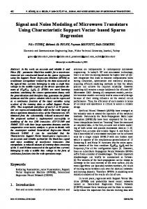
1. Introduction Optical power dividers and splitters belong to the most important components for optical communications, photonics integrated applications and optical signal processing. Power dividers with 2n output branches can be linking by two-branch waveguides but because the number of the output ports increases the dimensions of such splitter would be rather huge [1], [2]. In conventional three-branch splitter (or any odd-branch splitter) with a uniform index distribution most of the power is concentrated in the middle branch [3]. To avoid it is inevitable to reduce the transmission coefficient between the middle waveguide and the input waveguide by using the spacing area in the middle branch (see Fig. 1a). Another possibility for optical signal distribution between the channels is using of multimode interference (MMI) splitters [4], [5]. Compared with concatenations of junction splitters, the MMI splitters are attractive alterna-
Fig. 1. Schematic view of the proposed 1x3 dividers: a) threebranch splitter with triangular shaped spacing, b) multimode interference optical power splitter.
Conventional two, three and four branch optical splitters are usually made of glass, optical crystals (LiNbO3 etc.), semiconductors (AlGaAs/GaAs, InGaAsP/InP, Al2O3/SiO2, SOI, etc.) [6-10]. MMI splitters have also been demonstrated [11-14]. Both types of the splitters have suitable properties but the deposition technologies for their fabrication are complicated, expensive and environment unfriendly. From that point of view polymers are much better option, as they have appropriate properties such as suitable refractive index, low optical losses, reasonable time and temperature stability, feasible fabrication processes and, last but not least, they are mostly environment friendly [1518]. While the structures shown in Fig. 1b have been already realized in the polymer-based materials, the splitter shown in Fig. 1a has not been yet presented in any polymer material.
234
V. PRAJZLER, H. TŮMA, J. ŠPIRKOVÁ, V. JEŘÁBEK, DESIGN AND MODELING OF SYMMETRIC THREE BRANCH POLYMER …
In this paper we are going to present our new approach to construct the splitter of the type shown in Fig. 1a using Epoxy Novolak Resin (ENR) polymer as core waveguide layer. This resin has excellent optical properties (optical losses 0.15 dB/cm at 1310 nm, 0.46 dB/cm at 1550 nm) and can be easily prepared [19-21]. In our design silicon with silica buffer layer was used as a substrate because it provides good compatibility with the silicon-based technology and enables easy integration with other photonics structures and electrical elements. Polymethylmethacrylate (PMMA) was used as cover protection layer.
2. Design of the Single Mode Optical Polymer Ridge Waveguide Optical communication systems usually operate at wavelength range from 1260 to 1560 nm because the back bone optical networks are formed by silica fibers, which loss spectrum has two low-loss windows: one from 1200 to 1350 nm, and the one second ranges from 1450 to 1600 nm (see Fig. 2) [22]. That was the reason why we designed our photonics structures for operating in above mentioned wavelength ranges.
(ENR) and protection cover layer (PMMA) on silicon substrate.
Fig. 3. Schematic view of the ENR optical polymer ridge waveguide.
Refractive indices of every deposited layer were measured by ellipsometry in spectral range from 600 to 1600 nm (Fig. 4).
Fig. 4. Refractive indices of the applied layers measured by ellipsometry.
The obtained value of the refractive indices for the most important wavelengths and the data used for the designing are summarized in Tab. 1. wavelength (nm) Fig. 2. The low-attenuation regions of an optical fiber and wavelength spectrum used in optical telecommunications systems.
In photonics applications it would be also desirable to deposit all the components directly onto silicon substrates, however, silicon layer has very high refractive index and therefore it is necessary to insert so called transition buffer layer between the silicon substrate and the core waveguide layer and for that silica layer would be suitable. The design of the proposed optical waveguide structure is shown in Fig. 3 with polymer as the core waveguide layer deposited on silica-on-silicon substrate. PMMA polymer was used as the cover protection layer. In order to achieve the most accurate parameters of the structures, the first step of the design was deposition of the silica buffer layer (SiO2), optical waveguide layer
532 650 850 1260 1310 1550 1600
nSi (-) 4.069 3.811 3.629 3.507 3.499 3.475 3.471
refractive index ns nf (-) (-) 1.468 1.609 1.465 1.598 1.460 1.589 1.457 1.583 1.457 1.582 1.456 1.580 1.456 1.580
nc (-) 1.491 1.486 1.481 1.478 1.478 1.477 1.477
Tab. 1. The most important values of the refractive indices of the applied materials measured by optical ellipsometry and used for designing the structures of the dividers.
The designs of the single mode ridge waveguides were then done by means of modification of dispersion equation [23], which was refined by 3D Beam Propagation Method using BeamPROPTM software [24]. The thickness (hf) and width (w) of the ridge optical waveguide layer were set to be single-mode-guiding for operating wavelengths 650 nm, 1310 nm or 1550 nm. Thickness of the SiO2 buffer layer (hs) and PMMA cover protection layer
RADIOENGINEERING, VOL. 22, NO. 1, APRIL 2013
235
(hc) were set according to the calculated ones, which ensure that the out-coupled energy of the evanescent wave would be less than 1 %. Results of the simulations of the planar waveguides for the 1310 nm wavelength (TE modes) are shown in Fig. 5a and calculated fundamental mode of the single mode ridge waveguides operating at 1310 nm is shown in Fig. 5b.
be bigger than 2.72 µm and thickness of the PMMA protection cover layer hc has to be bigger than 1.88 µm. Dimensions of the TE single mode ridge waveguides, buffer layer and cover protection layer for operating wavelength 650 nm, 1310 nm and 1550 nm are shown in Tab. 2.
3. Design of the Three Branch Divider with Triangular Shape Spacing Normally in the three-branch waveguide with a uniform refractive index distribution the most of the optical power will be predominantly driven via the middle branch. To provide symmetrical distribution of the power triangular shape-spacing is inserted between the input and the middle output branches (see Fig. 1a). It will make the power quantity decreased in the middle branch while it is increased in two side branches. Applying this area the transmission coefficient between the main waveguide and the middle branch will be lowered. When the spacing area is zero, the structure becomes a conventional three-branch waveguide. When the spacing area is large the structure becomes a Y-branch-like structure, with a small transmission coefficient between the middle and the main waveguide [3]. However, the accurate shape and size of the triangular shape-spacing can be designed in such a way that the resultant dividing of the optical power will be symmetrical (the same in all three branches).
Fig. 5. a) Mode calculation of an optical planar waveguide for 1310 nm (TE modes), b) calculated fundamental mode of the ridge optical waveguide for 1310 nm. wavelength (nm) 650 1310 1550
hf (µm) 0.57 1.19 1.41
dimension of the ridge waveguides hc hs (µm) (µm) 0.89 1.31 1.88 2.72 2.23 3.22
w (µm) 0.55 1.61 1.37
Tab. 2. Calculated dimensions of the waveguides for single TE mode polymer waveguides (thickness of the buffer SiO2 layer hs and PMMA protection cover layer hc were calculated to get the out-coupled energy of the evanescent wave less than 1 %).
Calculated effective refractive indices for fundamental modes are approximately 1.5229 at 650 nm, 1.5227 at 1310 nm and 1.5110 at 1550 nm. The data show that between the heights hf of the ENR waveguide from approximately 2.7 µm to 5.1 µm a single mode guiding at 1310 nm can be achieved. For the hf bigger than 5.1 µm multiple modes will start propagating. To ensure that the out-coupled energy of the evanescent wave would be less than 1 % at 1310 nm, the thickness of the buffer SiO2 layer hs must
Our design also aimed to optimize the dimension of the triangular shaped spacing to achieve symmetrical 1x3 powers splitting. For that optimization we used 3D Beam Propagation Method (BPM) with BeamPROPTM software. The optimized dimensions of the polymer 1x3 branching splitter with triangular shaped spacing for operating wavelengths of 650 nm, 1310 nm and 1550 nm are shown in Tab. 3. wavelength (nm) 650 1310 1550
L (µm) 81.5 136.4 150.5
L2 (µm) 400 500 500
α (°) 0.7 0.7 0.7
P1 (%) 31.4 32.0 32.2
P2=P3 (%) 32.4 32.3 32.0
Tab. 3. Dimensions of the optical polymer 1x3 branching splitter with triangular shaped spacing (where P1 is output power at middle branch 2, P2 is output power in the branch 1 and P3 is output power in the branch 3). For more details see Fig. 1a.
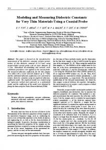
The simulations show that optimal distance (L) is 136.4 µm for operating wavelength 1310 nm and output power is approximately 32.3 % of the original value. Calculated output power normalized to the input power as a function of the propagation distance is shown in Fig. 6. Because the spreading of the signals in both left and right branches (2 and 3) is symmetrical, so in Fig. 6 only two curves actually appear: one overlapping curve of left and right branches and one curve of the middle branch. The normalized output amplitude is shown in Fig. 7.
236
V. PRAJZLER, H. TŮMA, J. ŠPIRKOVÁ, V. JEŘÁBEK, DESIGN AND MODELING OF SYMMETRIC THREE BRANCH POLYMER …
The multimode waveguide with width Wmmi, beat length L is defined as [4]:
L
0 1
4 neff Wmmi 3 0
2
(1)
where β0 and β1 are the propagation constants, λ0 is the free space wavelength and neff is effective refractive index of the MMI. According to symmetric interference mechanism, the single images of the input field will be obtained at the multimode section length:
Lmmi p Fig. 6. Normalized output power versus propagation distance for the design of the optical polymer 1x3 branching splitter with triangular shaped spacing for 1310 nm.
3 L 4
(2)
for p = 1, 2, …, while the N fold images obtained at distances (N is number of output waveguides):
Lmmi
p 3 L . N 4
(3)
4.1 Design of the Three Branch MMI Splitter For designing three branches MMI splitter we also used 3D BPM method using BeamPROPTM software and proposed three splitters for operating wavelength 650 nm, 1310 nm and 1550 nm. Optimized dimensions of such 1x3 MMI splitters are summarized in Tab. 4.
Fig. 7. Normalized output amplitude for the design of the optical polymer 1x3 branching splitter with triangular shaped spacing for 1310 nm.
wavelength (nm) 650 1310 1550
Lmmi (µm) 59.0 138.7 149.6
Wmmi (µm) 8 18 20
P1 (%) 26.4 26.1 27.9
P1=P2 (%) 26.2 26.5 27.2
Tab. 4. Dimensions of the design 1x3 splitter based on a principle of multi-mode interference (MMI).
4. Splitters Based on the Principle of Multi-Mode Interference After the three-branch waveguide with triangular shaped spacing we designed 1x3 splitter based on the principle of the multi-mode interference (MMI). The splitter consists of one input single mode waveguide, one multimode interference waveguide and three single output waveguides (Fig. 1b). Principle of the MMI optical splitter is based on the self-imaging effect [4], [5], [25], [26]. Generally, self-imaging is a property of the multimode waveguides by which an input field profile is reproduced as single or multiple images at periodic intervals along the propagation direction of the waveguide. In the special case where the odd modes are not excited in the multimode waveguide, the 1-to-N beam splitters can be realized with multimode waveguides four times shorter [27]. This condition can be achieved by input feeding the multimode waveguide with a symmetric field profile. The imaging is obtained by linear combinations of the even symmetrical modes, and this type of MMI mechanism is called symmetric interference [26].
Fig. 8. The simulation results in three branch MMI structure (The best imaging point is where the monitor plots share a maximum value).
Calculated output power normalized to the input power as a function of the propagation distance is shown in Fig. 8. The figure illustrates the optimal imaging length Lmmi for 1310 nm. The best imaging point in the terms of low loss and imbalance is around Z = 338.7 µm, where the
RADIOENGINEERING, VOL. 22, NO. 1, APRIL 2013
three power monitors have almost the same local maxima value. The optimal value of Lmmi is therefore 138.7 µm since the length of the input waveguide was set to 200 µm. Simulation results in the optimal length Lmmi ( = 1310 nm) is shown in Fig. 9a and the normalized output amplitude is shown in Fig. 9b. Similarly as in Fig. 6 (see above) also in Fig. 9a there are apparent only two curves as originally left and right branches overlap in one curve and the curve of the middle branch remains.
237
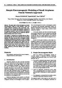
wavelengths, 650 and 1310 nm. Again, light propagation through the MMI multiplexer was modeled on the bases of two-dimensional BPM method using BeamPROPTM software. For simplicity the simulation was done for the dimensions w = 1.16 μm and Wmmi = 18 μm. Refractive indices used for simulation are given in Tab. 1. The results of the simulation are shown in Fig. 10 (Fig. 10a shows simulation for 650 nm and Fig. 10b for 1310 nm).
Fig. 10. The 2D-BPM simulation results in three branches MMI structure at a) 650 nm and b) 1310 nm.
Fig. 9. a) Results of simulation done at the optimal length Lmmi, and = 1310 nm. b) Output field of the optimized MMI structure ( = 1310 nm).
The simulations show that our MMI structure for the dimension of the single mode waveguide and for Lmmi= 138.7 µm and Wmmi= 18 µm ( = 1310 nm) has the output power around 26%.
4.2 Design of the Three Branch Splitter for 650 nm / 1310 nm As mentioned above the MMI splitter consists of single mode input/output waveguides and a middle multimode interference waveguide. Function of the MMI splitter is based on the self-imaging effect and such structure operates at one wavelength λ0 (see equation 1). Now we are going to demonstrate the design of our MMI structure that would simultaneously support two
The first resonance (for wavelength of 1310 nm) maximum output energy was found at Lmmi = 140 μm and it splits to be around 28.1 % (for output 1 and 3) and 30 % (for output 2). The second resonance for 1310 nm was found at Lmmi = 180 μm and it again splits to around 27.3 % (for output 1 and 3) and 29.0 % (for output 2). More details can be seen in Fig. 10b. For 650 nm, the Lmmi will be 175 μm with the non-symmetrical output energy being 2x32 % (output waveguides 1, 3) for the outer outputs and 30.8 % (output waveguide 2 - see Fig. 10a) for the middle one. In the ideal case the simulated output energy will be 3x33%, but it will be that case only if the input and output waveguides are the single-mode ones. But, a single mode supported at 1310 nm becomes a three-mode one at 650 nm. Also, one value of the Lmmi that would allow for the maximal energy (3x33 %) output resonance at both 650 and 1310 nm cannot be found. Instead we may do a compromise by setting the Lmmi= 378 μm, that will somehow lower the maximal output energy (3x29.5 %) but would work for both wavelengths (650 and 1310 nm). However one should still bear in mind that for the right function of the divider the inputs as well as the output waveguides are to be the single-mode ones. However, in practice it is very
238
V. PRAJZLER, H. TŮMA, J. ŠPIRKOVÁ, V. JEŘÁBEK, DESIGN AND MODELING OF SYMMETRIC THREE BRANCH POLYMER …
difficult to find such dimensions of the waveguides that would fulfill that condition. If, in reality, it is not fulfilled and the number of the output modes is higher, the resulting energy will be lower as it splits into the pertinent mutually interacting modes. There is a question, if, in principle, it is possible to construct an MMI splitter, which would simultaneously operate at two, say commonly used communication wavelengths 1310 and 1550 nm. Though it is highly desirable it would actually mean that the interference part Lmmi would be enormously huge. On the other side, structures having reasonably small Lmmi will have very low efficiency as they would have very low output energies (e.g., for Lmmi = 130 μm it is around 14.9 %).
5. Conclusion We reported about design and modeling of two new types of polymer optical planar power 1x3 splitters done by Beam Propagation Method using RSoft software for three operating wavelengths at 650 nm, 1310 nm and 1550 nm. Proposal of a three-branch waveguide with triangular shaped spacing was elaborated as well after which we finally designed 1x3 splitter based on a principle of multimode interference. Simulations showed that our three-branch waveguide with triangular shaped spacing had higher efficiency and can utilize broader spectrum of the wavelengths comparing to MMI. However, efficient coupling to a standard optical fiber would require a longer structure, which may be more demanding for the real structure because of possible bigger optical losses etc. MMI structures have ultra-compact dimensions but they can operate only at one wavelength, moreover they are rather complicated and their manufacturing tolerances are limited. Generally, splitters with triangular shaped spacing can operate in wider spectral range and manufacturing tolerances are higher though dimensions of the structures are larger than the MMI structures. Finally the structure with the triangular spacing would provide better opportunity. Here we have demonstrated an entirely new option to construct such a splitter using cheap and feasible way.
Acknowledgements Our research is supported by the Ministry of Industry and Trade of the Czech Republic by grant no. FR-TI3/797 and by the research program of the Czech Technical University in Prague by project no. SGS11/156/OHK3/3T/13.
References [1] YABU, T., GESHIRO, M., MINAMI, N., SAWA, S. Symmetric
three-branch optical power divider with a coupling gap. Journal of Lightwave Technology, 1999, vol. 17, no. 9, p. 1693-1699. [2] HUANG, C.C., CHANG, C.Y., WANG, W.S. Single-mode fourbranch power divider with coupled wide-angle waveguides. Microwave and Optical Technology Letters, 2003, vol. 38, no. 4, p. 337-341. [3] BANBA, S., OGAWA, H. Novel symmetrical three-branch optical waveguide with equal power division. IEEE Microwave and Guided Wave Letters, 1992, vol. 2, no. 5, p. 188-190. [4] SOLDANO, L. B., PENNINGS, E. C. M. Optical multi-mode interference devices based on self-imaging - principles and applications. Journal of Lightwave Technology, 1995, vol. 13, no. 4, p. 615–627. [5] BESLEY, J. A., LOVE, J. D., LANGER, W. A multimode planar power splitter. Journal of Lightwave Technology, 1998, vol. 16, no. 4, p. 678-684. [6] HARUNA, M., BELANGER, M., YIP, G. L. Passive 3-branch optical power divider by K+-ion exchange in glass. Electronics Letters, 1985, vol. 21, no. 12, p. 535-536. [7] WANG, T.J., HUANG, C.F., WANG, W.S. Wide-angle 1x3 optical power divider in LiNbO3 for variable power splitting. IEEE Photonics Technology Letters, 2003, vol. 15, no. 10, p. 1401- 1403. [8] MIN, D.S., LANGER, D. W., PANT, D. K., COALSON, R. D. Wide-angle low loss waveguide branching for integrated optics. Integrated Optics, 1997, vol. 16, no. 4, p. 331-342. [9] SAKAI, A., FUKAZAWA, T., TOSHIHIKO, B. Low loss ultra small branches in silicon photonics wire waveguide. IEICE Trans. Electron., 2002, vol. E85-C, no. 4, p. 1033-1038. [10] GAO, Y., GONG, Z., BAI, R., HAO, Y.L., LI, X.H., JIANG, X.Q., WANG, M.H., PAN, J.X., YANG, J.Y. Multimode-waveguidebased optical power splitters in glass. Chinese Physics Letters, 2008, vol. 25, no. 8, p. 2912-2914. [11] HEATON, J. M., JENKINS, R. M., WIGHT, D. R., PARKER, J. T., BIRBECK, J. C. H., HILTON, K. P. Novel 1-to-N way integrated optical beam splitters using symmetric mode mixing in GaAs/AlGaAs multimode waveguides. Applied Physics Letters, 1992, vol. 61, no 15, p. 1754 – 1756. [12] WANG, F., YANG, J.Y., CHEN, L.M., JIANG, X., WANG, M. Optical switch based on multimode interference coupler. IEEE Photonics Technology Letters, 2006, vol. 18, no. 1-4, p. 421-423. [13] JINGTAO, Z., HUIHUI, Z., XINYU, LIU Design and fabrication of a compact multimode interference splitter with silicon photonic nanowires. Chinese Optics Letters, 2009, vol. 7, no. 11, p. 1041 to 1044. [14] BLAHUT, M., FRONIEWSKI, D. Self-imaging effects in curved gradient index multimode interference structures made by K+-Na+ ion exchange. Optica Applicata, 2009, vol. 39, no. 3, p. 445-458. [15] ELDADA, L., SHACKLETTE, L. W. Advances in polymer integrated optics. IEEE Journal of Selected Topics in Quantum Electronics, 2000, vol. 6, no. 1, p. 54-68. [16] MA, H., JEN, A.K.Y., DALTON, L. R. Polymer-based optical waveguides: Materials, processing, and devices. Advanced Materials, 2002, vol. 14, p. 1339-1365. [17] RABIEI, P., STEIER, W. H., ZHANG, C., DALTON, L. R. Polymer micro-ring filters and modulators. IEEE Journal of Lightwave Technology, 2002, vol. 20, p. 1968–1975. [18] WONG, W.H., LIU, K.K. CHAN, K.S., PUN, E.Y.B. Polymer devices for photonics applications. Journal of Crystal Growth, 2006, vol. 288, no. 1, p. 100-104. [19] BECHE, B., PELLETIER, N., GAVIOT, E., ZYSS, J. Single-mode
RADIOENGINEERING, VOL. 22, NO. 1, APRIL 2013
239
TE00-TM00 optical waveguides on SU-8 polymer. Optics Communications, 2004, vol. 230, no. 1-3, p. 91-94. [20] TUNG, K.K., WONG, W.H., PUN, E.Y.B. Polymeric optical waveguides using direct ultraviolet photolithography process. Applied Physics A Materials Science & Processing, 2005, vol. 80, p. 621–626. [21] PRAJZLER, V., LYUTAKOV, O., HUTTEL, I., BARNA, J., SPIRKOVA, J., NEKVINDOVA, P., JERABEK, V. Simple way of fabrication of epoxy novolak resin optical waveguides on silicon substrate. Physica Status Solidi C, 2011, vol. 1–4. DOI 10.1002/pssc.201084031. [22] MUKHERJEE, B. Optical WDM Networks. Springer, 2006. [23] POLLOCK, C. R. Fundamentals of Optoelectronics. Richard D Irwin, 1994. [24] RSoft Design Group, www.rsoftdesign.com.
User
Guide
BeamPROP
[25] SHI, Y., DAI, D. Design of a compact multimode interference coupler based on deeply-etched SiO2 ridge waveguides. Optics Communications, 2007, vol. 271, no. 2, p. 404–407. [26] IBRAHIM, M. H., SHUH-YING, L., MEE-KOY, C., KASSIM, N. M., MOHAMMAD, A. B. Multimode interference optical splitter based on photodefinable benzocyclobutene, (BCB 4024-40) polymer. Optical Engineering, 2007, vol. 46, no. 1, p. 013401-1013401-4. [27] JENKINS, R. M., DEVERAUX, R. W. J., HEATON, J. M. Waveguide beam splitters and recombiners based on multimode propagation phenomena. Optics Letters, 1992, vol. 17, no. 14, p. 991-993.
About Authors … Václav PRAJZLER was born in 1976 in Prague, Czech Republic. In 2001 he graduated from the Faculty of Elec-
trical Engineering, Czech Technical University in Prague, Department of Microelectronics. Since 2005 he has been working at the Czech Technical University in Prague, Faculty of Electrical Engineering, Dept. of Microelectronics as a research fellow. In 2007 he obtained the PhD degree from the same university. His current research is focused on fabrication and investigation properties of the optical materials for integrated optics. Hynek TŮMA was born in 1988. He graduated to Bc master from the Faculty of Electrical Engineering, Czech Technical University in Prague, Dept. of Microelectronics in 2011. His master thesis is focused to design intelligent lighting in the building. Jarmila ŠPIRKOVÁ graduated from the Faculty of Natural Science, Charles University in Prague and from the Institute of Chemical Technology, Prague (ICTP). Now she is with the Dept. of Inorganic Chemistry at the ICTP. She has worked there continuously in materials chemistry research and since 1986 she has been engaged in planar optical waveguides technology and characterization. She is the Assistant Professor at the ICTP giving lectures on general and inorganic chemistry. Vítězslav JEŘÁBEK was born in 1951. 1975: MSc. from FEE-CTU in Prague. 1987: PhD. in Optoelectronics. 1976– 91: TESLA Research Institute, Prague. 1981: Optoelectronics Division, dynamics and modeling of optoelectronics devices & broad band optoelectronic modules. 1991– 98: Head R&D lab. Dattel Ltd. -integrated optoelectronics modules and systems. Since 1999: teaching technology of optics and optoelectronics components and systems for transmission and processing of information. Author of 35 technical papers, 2 printed lectures and 3 patents, Member IEEE, Committee member of IEE in the Czech Republic.