e-ISSN : 0975-4024
Kalmeshwar N. Hosur et al. / International Journal of Engineering and Technology (IJET)
Design and simulation of Low Power Successive Approximation Register for A/D Converters using 0.18um CMOS Technology Kalmeshwar N. Hosur#1, Girish V. Attimarad *2, Harish M. Kittur ##3, S. S. Kerur #4 #
Department of Electronics & Communication Engg., S.D.M. College of Engineering & Technology, Dharwad, Karnataka, India, 1
[email protected] 4
[email protected] * Department of Electronics & Communication Engg., Dayanand Sagar College of Engineering, Kumarswamy Layout, Bangalore, Karnataka, India, 2
[email protected] ## School of Electrical Sciences, VIT University, Vellore, Tamilnadu, India . 3
[email protected] Abstract— This Paper presents the design and simulation of low power successive approximation register for the Analog to Digital Converters (ADC) using 0.18um CMOS Technology. This acts as digital part of successive approximation ADC. The principle of the Successive Approximation Register (SAR) circuit is to determine the value of each bit of the ADC in a sequential manner, depending on the value of the comparator output. If an N bit analog to digital converter is implemented, there are 2N possible conversion output values, which means that the SAR needs at least 2N states and so, as minimum, N FFs. For N bit SAR ADC, the sequence/code register SAR structure requires 2N Flip-Flops and hence power consumption and area occupied is more and Non redundant SAR structure requires N Flip-Flops and a little combinational Logic and hence power consumption is less and area occupied is also less compared to that of Conventional. For 10 bit SAR architecture, the dynamic power consumed by sequence/code register SAR structure is 63.4359uW and non reduandant SAR architecture is 49.2569 uW. The total power reduction using non redundant architecture is 22.35%. Keyword - Analog- to- Digital converter, Digital- to- Analog converter, Successive Approximation, Low Power. I. INTRODUCTION The rapid development of portable devices such as cell phones, laptops and implantable chips in human bodies and the progress in technology have made the power consumption of microelectronic devices a major concern. The more amount of power is consumed by digital circuits compared to analog circuits. In order to reduce the power consumption of digital circuits, some techniques have been proposed at both the circuit and system level, such as leakage reduction, voltage scaling, clock gating and architectural design techniques, logic reordering and interconnect optimization. In some ultra low voltage applications such as biomedical applications, sub threshold circuits, in which the transistors are biased below threshold voltage, are used. In this we have discussed different design approaches of SAR. Successive approximation analog to digital converter (SAR ADC) is a capable approach in moderate speed and resolution applications. SAR ADC implements the binary search algorithm using SAR control logic. In general, basically there are two approaches of designing SAR logic. The first one which is proposed by Anderson consists of a sequencer register and code register. In this type of SAR logic 2N flip flops are used. The second is proposed by Rossi, contains N flip flops and some combinational logic [1]. SAR ADC has the benefit of power efficiency compared with other ADC architectures. Moreover, SAR ADC benefits from technology downscaling because of two main reasons: (1) SAR ADC is an op amp-free architecture; and (2) SAR ADC mainly consists of digital circuits. In other words, SAR ADC does not require high gain and high bandwidth op amps to guarantee the linearity. In advance process nodes, a high-performance op amp consumes huge power, and suffers from short channel effect and low supply voltage [2]. Synchronous and asynchronous solutions are investigated for low power SAR control logic. For high-speed SAR ADCs in order to avoid a high-frequency system clock asynchronous processing has been normally used [4]. Many of the limitations of classical SAR implementation are solved by binary search ADC based on Switched Capacitor (SC) realization. In fact, in CMOS technology SC circuits have frequently been selected
p-ISSN : 2319-8613
Vol 8 No 2 Apr-May 2016
742
e-ISSN : 0975-4024
Kalmeshwar N. Hosur et al. / International Journal of Engineering and Technology (IJET)
because their gain depends only on the ratio between the capacitances, rather than on the value of a single capacitor [5]. LFSR Based SAR Logic is presented in [6]. An LFSR is a shift register that, when clocked, advances the signal through the register from one bit to the next most-significant bit.
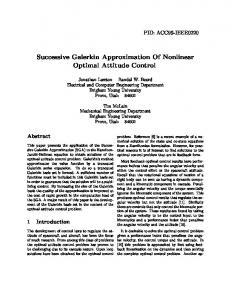
Fig. 1. SAR ADC structure
The basic SAR ADC structure is shown in Fig.1 and mainly consists of sample and Hold circuit, comparator, SAR logic and DAC. This paper describes Design and simulation of 10-bit low power SAR structure. Section II discusses the low power techniques in digital design. Section III discusses the low power SAR design. Section IV explains the implementation using Cadence. Section V contains simulation results and Section VI contains conclusions. II. LOW POWER TECHNIQUES IN DIGITAL DESIGN A. Supply voltage reduction One of the most important strategies for lowering power consumption is supply voltage scaling in digital circuit design, since dynamic power consumption is proportional to the square of operating voltage. On one hand, reducing the supply voltage will lower the dynamic power consumption, but on the other it lowers the speed, and thus there should be a trade-off in reducing the supply voltage to maintain the system at the desired speed. Low power design is the major concern while the speed has a secondary importance in some applications, such as biomedical devices and sensor networks. For ultra-low power applications Sub-threshold design as a very promising method has been broadly used until now. Since the maximum achievable speed in the circuits that are designed in the sub-threshold area is limited, these circuits are used in ultra-low power applications that need low to medium speed. The supply voltage in this area is below the threshold voltage of transistors (VDD