Design and Sliding Mode Control for PMSG Based Wind Power System Connected to a Non-ideal Grid Voltages Youssef Errami*, Abdellatif Obbadi, Smail Sahnoun, Mohammadi Benhmida, Laboratory: Electronics, Instrumentation and Energy- Team: Exploitation and Processing of Renewable Energy, Department of Physics, Faculty of Science, University Chouaib Doukkali, Eljadida, Morocco E-mail:
[email protected] Abstract— This study presents a control scheme of the electronic interface of a grid connected Variable Speed Wind Energy Generation System (VS-WEGS) based on a Permanent Magnet Synchronous Generator (PMSG). The proposed system consists of wind turbines (WT) and 2 PMSGs connected to the electric network by back-to-back Voltage Source Converter (VSC) with a common dc-link. The generator-side converters are employed to attain Maximum Power Point Tracking (MPPT). The grid-side regulator controls the reactive power flow, the voltage at the dc link between both sides and the power factor during wind variations. The reliability and effectiveness of wind energy is shown to be depending on the applied control strategy. So, the control schemes are based on Sliding Mode Control (SMC) for control of both generators and grid-side converters of a VSWEGS. The performance of the system has been demonstrated under varying wind conditions and under a grid voltage dip. The proposed SMC strategy is compared with the conventional Vector Control (VC) method. The simulation results show a good performance of the proposed sliding mode control. Keywords- VS-WEGS; PMSG; MPPT; sliding mode control; Lyapunov theory; grid fault.
I. INTRODUCTION Over the last decade, the world has been turning to the renewable energy sources. Among various varieties of renewable energy, Variable Speed Wind Energy Generation System (VS-WEGS) has been noted as the most quickly growing technology and becomes the most competitive form of renewable green energy [1-2]. In the area of VS-WEGS, Permanent Magnet Synchronous Generators (PMSG) possess some attractive qualities such as high power density, implementation facility, absence of the gearbox and efficient energy production, compared with other generator technologies [3-4]. Accordingly, with those advantages, PMSG is found to be appropriate for application in large wind power system. Habitually, the VS-WEGS with a PMSG is coupled to the grid via an AC-DC-AC converter system. Consequently, the wind power system does not need to synchronize its rotational velocity with the electric network frequency. Also, the reliability and effectiveness of wind energy is shown to be depending on the applied control strategy. On the other hand, diverse control strategies can be adopted for the operation of the PMSG and electric network side converters in order to
Mohammed Ouassaid, Mohamed Maaroufi Department of Electrical Engineering, Mohammadia School’s of Engineers, Mohammed V University, Rabat, Morocco
increase the annual energy yield of VS-WEGS. Standard control of VS-WEGS is generally based on Vector Control (VC) which is accomplished by Proportional Integral (PI) regulators [5-7]. However, the major disadvantage is the tuning of the PI parameters. Then, the performance depends greatly on accurate VS-WEGS parameters. So as to tackle such problem, Direct Power Control (DPC) and Direct Torque Control (DTC) were proposed in [8–9]. The hysteresis regulators and a switching lookup table are used to maintain estimations of the torque, the flux, reactive and active power in bounds. So, direct control techniques minimize the use of VS-WEGS parameters, reduce the complexity of the VC approach and can achieve improved dynamic performance with simple configuration. But, the main drawbacks for direct control techniques are that the switching frequency of power electronic converter varies with operating situations and there are important ripples in flux /torque or reactive/active powers at stable state. Furthermore, its performance declines during low velocity operation. Then, because of the direct control techniques and VC suffers from some limited performances, Sliding Mode Control approach (SMC) can be used. SMC is a nonlinear algorithm which based on the variable structure control strategy. It presents many attractive features, such as robustness to parameters uncertainties of systems, external disturbance rejection, fast dynamic response and good performance against unmodelled dynamics [10–11]. Thus, SMC can cope with the exacting characteristics presented by VS-WEGS such as usual uncertainties in both the electrical and aerodynamic the models, and the arbitrary variation of the wind velocity. This paper proposes a variable structure sliding mode control scheme for the back-to-back converter of VS-WEGS based on the PMSG. The generator side converter controllers are employed to regulate the velocities of the PMSGs with Maximum Power Point Tracking (MPPT). So, the wind turbines are working at highest effectiveness. The grid side regulator controls the dc link voltage and the reactive power flow independently. Also, it is employed to control the power factor during wind variations. Besides, the pitch control systems are activated once the PMSG velocities increase beyond their rated values. Consequently, the power extracted from the wind energy is reduced. The performance of the VSWEGS has been verified under varying wind conditions and under a grid voltage dip.
978-1-4673-7894-9/15/$31.00 ©2015 IEEE
The rest of the paper is organized as follows. The models of the wind turbine systems and the PMSGs are developed in section II. In section III, the control scheme is presented. Section IV presents the simulation results. The performance of the VS-WEGS has demonstrated under varying wind conditions and under a grid voltage dip. Also, the proposed SMC strategy is compared with the conventional VC method. Finally, Section V presents some conclusions. II.
SYSTEM MODELING
A. Modeling of individual wind turbine The amount of power captured by the wind turbine is given as [8]: 1 (1) PTurbine ACP ( , )v3 2 where, is the air density ( kg/m3 ), A is the swept area (m2), CP is the power performance coefficient of the turbine which is influenced by the pitch angle of rotor blades ( in degrees ) and v is the wind velocity (in m/s). The tip-speed ratio is given by: R m (2) v where R and m are the blade length (in m) and the wind turbine rotor velocity (in rad/sec), respectively. A generic equation is employed to model the coefficient of power conversion CP ( , ) as [7]: 21
CP
( ) 1 116 ( 0.4 5)e r 2 r
1
1 0.035 r 0.08 3 1
(3)
The maximum value of CP , that is CP max 0.41 , is reached for optim 8.1 and for 0 . Hence, there is one particular
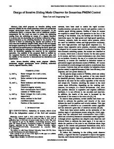
optim , optimal power coefficient, and an optimal turbine rotating velocity moptim , under which CP takes a maximum value CP max . Also, the maximum power can be captured from the wind. Accordingly, the turbine system works in Maximum Power Point Tracking (MPPT) [2], as depicted in Fig. 1 B. PMSG Model The electrical model of the PMSG is defined in the rotating reference frame d-q and is given as follows [8]: diq (4) Lq Rg iq vgq e f e Ld id dt di (5) Ld d Rg id vgd e Lq iq dt where vgd and vgq are the direct stator and quadrature stator voltage, respectively. id and
iq
resistance, Lq and Ld are the quadrature and direct axis inductances, f is the magnetic flux of the permanent magnets and e is the electrical rotating velocity of the generator, defined by: e pnm (6) where pn is the number of pole pairs of the PMSG and m is the mechanical rotating velocity. If id 0 , the electromagnetic torque can be derived to be: 3 (7) Tem pn f iq 2 The dynamic equation of the wind turbine is described by: dm 1 (Tem F f m Ttg ) (8) dt Jt where J t is the moment of inertia , F f is the viscous friction coefficient and Ttg is the mechanical torque developed by the wind turbine. Ttg is given as: Ttg
III.
1 1 ACP ( , )v3 2 m
(9)
NONLINEAR SLIDING MODE CONTROL
FOR VS- WEGS
A. MPPT and Pitch Controller For a given wind velocity, the objective of the MPPT is to regulate the rotating speeds of turbines to moptim . Then, the maximum power can be extracted from the wind and the powers of the wind turbine systems are controlled to follow the optimal power very well (Fig. 1). In this case, the optimal rotational speed of each PMSG moptim can be estimated as follows [7]:
moptim
voptim
(10) R Consequently, the maximum extracted power of the turbines is given as follows: PTurbine _ max
Rmoptim 1 ACP max optim 2
3
whenever the wind speed exceeds the rated value, the pitch control is activated to prevent overspeeding of the wind turbine system by increasing the angle of blades . The employed pitch angle system is illustrated in Fig. 2 where Pgp is the generated power.
are the direct stator and
quadrature stator current, respectively. Rg is the stator
(11)
Figure 1. Wind generator power curves at various wind speed
B. Control of the generator side converter with nonlinear sliding mode control based MPPT The generator-side converters control the PMSG velocities to make the wind turbine working at highest efficacy. Then, these converters work as a drivers to control the PMSGs operating at optimum rotor velocity m _ optim which is determined by the MPPT algorithm. On the other hand, SMC is employed to attain MPPT for a given wind velocity. In addition, it is deduced from equations (7) and (8) that the PMSG velocity can be controlled by regulating the q-axis stator current component ( iq ). Based on the nonlinear SMC theory introduced in [12], the error of PMSG speed is selected as sliding surface: S1 m _ optim m (12) Hence, using (8), the time derivative of S can be calculated as: dS1 dm _ optim 1 (13) (Tem Ttg Ff m ) dt dt J The main control goal ( m m _ optim ) is guaranteed if [13]: dS1 0 dt Besides, to realize commutation around the surface of each component of the control algorithm is proposed calculated as the addition of two terms [13]: uc uc q uc n S1
(14) SMC, to be (15)
where uc q is the equivalent control term. uc q is calculated from the expression: dS1 (16) 0 dt while, uc n is used to assure the attractiveness of the PMSG velocity to be controlled towards the commutation sliding mode surface. Then, the control signal of the following form can assure the requirements of the reaching mode: uc n k1 sgn(S1 ) (17)
where k1 is a positive constant and sgn( S1 ) is a sign function defined as: S1 1 S sgn( S1 ) 1 S1 (18) S1 1 m MAX
k
mrated
Prated
PI
Pgp
Figure 2. VS-WEGS pitch angle controller.
where is the width of the boundary layer and it should be chosen thoughtfully. Based on equations (7), (8), (12-18), the following equation for the system of velocity can be obtained: dm _ optim 2 iq ref (Tem J t F f m J t k1 sgn(S1 )) (19) 3 pn f dt id ref 0
(20) On the other hand, to achieve the control of the currents components id and iq , the errors of quadrature and direct currents are selected as sliding surface: S2 iq ref iq
(21)
S3 id ref id
(22)
where iq ref and id ref are the references of the quadrature stator and direct stator current, respectively. Thus, dS2 diq ref diq (23) dt dt dt dS3 did ref did (24) dt dt dt when the trajectories of quadrature and direct currents coincide with the sliding surfaces: dS (25) S2 2 0 dt dS (26) S3 3 0 dt Consequently, based on equation (4-5), (15) and (21-26) the control voltage components of q axis and d axis are defined by: vq ref Lse id e f Rg iq Ls
diq ref dt
Ls k2 sgn(S2 )
vd ref Lseiq Rg id Ls k3 sgn(S3 )
(27) (28)
where k2 0 and k2 0 . Theorem 1: If the dynamic SMC rules are designed as (19), (20), (27) and (28), consequently the global asymptotical stability is insured. Proof: The demonstration of the theorem 1 will be approved out using the Lyapunov theory of stability. Then, the Lyapunov function can be chosen as: 1 1 1 (29) 1 S12 S22 S32 2 2 2 According to the theorem of Lyapunov stability, the sliding mode occurs if: d 1 0 (30) dt The dynamic of the Lyapunov function 1 defined in (29) is expressed as: dS d 1 dS dS S1 1 S2 2 S3 3 (31) dt dt dt dt Using equations (12-13), (19-20), (21-24) and (27-28), we can rewrite (31) as:
d 1 (32) k1S1 sgn(S1 ) k2 S2 sgn(S2 ) k3 S3 sgn(S3 ) dt Consequently, d 1 (33) k1 S1 k2 S2 k3 S3 0 dt Consequently, the global asymptotical stability is insured and the main control goal ( m m _ optim ) is guaranteed. Fig.3.
illustrates the double closed-loop control diagram for each generator side converter under SMC based MPPT. C. Grid side converter control using SMC The grid-side converter regulator controls the active power flow by adjusting the dc-link voltage U dc at its reference value, and the reactive power independently. Accordingly, it can regulate the grid side power factor during the change of wind velocity [14]. The schematic diagram of the grid-side inverter based on the SMC is illustrated by Fig. 4. It consists of two control loops, the internal control loops regulates q-axis current and d-axis current, but outer voltage loop which outputs the direct reference current and regulates the dc-link voltage by controlling the output power. In the rotating dq reference frame
The dynamic of the DC-link voltage is given by: dU dc v 3 vq ( iq g d id g ) idc (36) dt 2C U dc U dc where idc and U dc are the grid side transmission line current and the dc-bus voltage respectively. Furthermore, the active power and reactive power can be expressed as: 3 (37) Q Viq g 2 3 (38) P Vid g 2 Therefore, active and reactive power control can be achieved by adjusting the direct and quadrature grid current components, respectively. Moreover, the q-axis current reference iq g ref is generated by the reactive power Qref according to (37) whereas the d-axis current reference id g ref is produced by dc-bus voltage regulator to control the active power flow. On the other hand, to achieve the control of the currents components iq g and id g , the following surfaces are selected:
and if the grid voltage space vector u is oriented on d-axis, the electrical equations describing the behaviour of the grid-side converter are given by [15]: did g (34) ed V L f R f id g L f iq g dt diq g (35) eq L f R f iq g L f id g dt where L f and R f are the filter inductance and resistance respectively; ed and eq are the inverter d-axis q-axis voltage components respectively; id g and iq g are the d-axis current and q- axis current of grid. V is the grid voltage component in the d-axis voltage component. Turbine
DC
Prated m _ rated
MPPT & Pitch Control
m _ optim
m
U dc
PWM
Pts
iga , igb , igc 3
iq
2
id
3
vq ref
S5 id g ref id g
(40)
did g ref dt
L f iq g R f id g L f k5 sgn(S5 )
vq g ref L f id g R f iq g L f k4 sgn(S4 )
AC
•
(39)
Then, the dynamics of S 4 and S5 are: dS4 diq g ref diq g (41) dt dt dt dS5 did g ref did g (42) dt dt dt In addition, when the trajectories of direct and quadrature currents coincide with the sliding surfaces: dS (43) S4 4 0 dt dS S5 5 0 (44) dt As a result, the controls voltage of q and d axis axis are: vd g ref V L f
PMSG
S4 iq g ref iq g
2
vd ref
Figure 3. Schematic of SMC approach for individual PMSG rectifier.
(46)
where k4 0 , k5 0 . Theorem 2: If the dynamic SMC rules are designed as (45), and (46), consequently the global asymptotical stability is insured. Proof: The demonstration of the theorem 2 will be approved out using the Lyapunov theory of stability. Then, the Lyapunov function can be proposed as: 1 2 1 2 S4 S5 2 2 The sliding mode occurs if: d 2 0 dt 2
Equations (19-20), (27) and (28)
(45)
(47)
(48)
The wind speed profiles are depicted in Fig. 5(a). The power conversion coefficients C p , pitch angles , rotor angular velocities of the PMSGs and total power generated of VS-WEGS are shown from Fig. 5(b)–(f), respectively. The rated wind velocity considered in the simulation is vn 12.4 m/s. As can be observed in these figures, the rotor angular velocity fluctuations and the output power variation are the same as wind speed, with a limitation. Also, pitch angles are controlled depending on the wind velocities. So, when the wind speed is smaller than the rated velocity, the pitch angles are kept constant (0°) and the power performance coefficients of the turbines are fixed at its maximum value, around 0.41. On the contrary, since the incoming wind exceeded the rated wind, the pitch angles increase and the power coefficients decrease to limit the rotor velocities to the rated speed. As can be seen from Fig. 5(f), if the wind velocity is above the threshold, the power extracted is maintained in its rated value (4MW). As shown in Fig. 5(e), the mechanical velocity of the PMSG1 controlled with the proposed strategy tracks its reference, obtained from MPPT algorithm, successfully with rapid response. From Fig. 5(g-h), the grid voltage is in phase with the current since the reference of reactive power is set to zero. Thus, unity power factor of VS-WEGS is attained approximatively and is independent of the fluctuation of the wind velocity but only on the reactive power reference ( Qref ). From Fig. 6, the dc link voltage is regulated toward the desired reference (1700 V). In order to test the system performances under disturbed scenario, symmetrical Three-Line-to-Ground faults (3LG) are considered as network disturbances. Fig. 7 illustrates the configuration of the VS-WEGS with the power network system. Also, the faults take place at the Bus 3.
Based on equation (47), the time derivative of 2 can be calculated as: dS d 2 dS (49) S4 4 S5 5 dt dt dt Using equations (34-35), (39-44) and (45-46), we can rewrite (49) as: d 2 (50) k4 S4 sgn(S4 ) k5 S5 sgn(S5 ) dt As a result, d 2 (51) k4 S4 k5 S5 0 dt Finally, the asymptotic stability in the loop of current is guaranteed and the dc-bus voltage control tracking is accomplished. The diagram of the dc-link voltage and current controllers for grid-side inverter is depicted in Fig. 4. IV. SIMULATIONS RESULTS To verify the validity of the proposed variable structure SMC scheme for a 4 MW- PMSG wind farm, this paragraph presents the simulated responses of the VS-WEGS under varying wind conditions and under a grid voltage dip. The MATLAB/Simulink simulations for the system shown in Fig. 4 are carried out. The parameters of the system are shown in the Table I. Also, during the simulation, for the PMSG side rectifier control the d-axis current reference id ref and Qref are set to zero. The grid voltage phase lock loop (PLL) system is employed to achieve the synchronization with the electric network. Fig. 5 illustrates the VS-WEGS performance in the normal grid conditions.
PMSG1
•
AC DC
•
Filter
DC
•
Transformer 0,8KV/20KV
AC
•
Lf , Rf
Electric network
•
ia , ib , ic
PWM
1
PLL 3
PMSG2 AC
vq g ref
3
2
vd g ref
iq g
2
id g
3
2
V
DC
Equations (45), (46)
U dc
2 U dc ref
Figure 4. Schematic of SMC strategy for VS-WEGS.
Qref
overshoot and quicker response. Fig. 9 depicts the difference in frequency performance between the two controlling approaches. So, it can be observed that maximum frequency deviations are reduced from 2.5 Hz to less than 0.2 Hz with SMC technique. Besides, the frequency excursion is detained earlier in SMC strategy. Consequently, the frequency deviations are considerably diminishing during the voltage dip and with SMC method, the system is few responsive to power grid fault.
The fault occurs at 7 sec and it lasts for 200 ms. Fig. 8 and Fig. 9 compare the VS-WEGS dynamic performance under the proposed SMC approach and classic PI control. Fig. 8 shows the variations and the enlarged view corresponding to the variation of three phase voltage at Bus 4 during and after the grid fault period. It is clearly observed from the comparative responses that, if using PI regulators, three phase voltage fluctuations were more severe deformed. In contrast, with SMC approach, the grid voltage can be recovered rapidly after fault elimination. Moreover, the proposed SMC permits lower
(a) Instantaneous wind speeds (m/s).
(c) Pitch angles .
(e) Speed of PMSG1 (rd/s).
(g) Three phase current and voltage.
(b) Variation of coefficients of power.
(d) Speeds of PMSGs.
(f) Power generated (W).
(h) Three phase current and voltage (zoom).
Figure. 5. Waveforms of VS-WF characteristics with SMC and normal grid condition.
PMSG1
Bus 4
•
AC DC
DC
•
Bus 6
Bus 5
20kV /60kV Electric network
1km Transmission line 1
AC 380 V/22kV
Yn YN PMSG2
1km 1km
AC
1km
DC
Bus 3 Bus 1
Nonlinear SMC
Load 1 P1= 100KW
Bus 2 Load 3 P3= 150KW
Figure 7. Configuration of the VS-WF with the power network system.
Fault Load 2 P2=1MW
REFERENCES [1]
[2]
Figure 6. DC link voltage (V).
[3]
[4]
[5] (a)
Sliding mode control
(b) PI controller
Figure. 8. Zoom-in view of three phase voltage at Bus 4
[6]
[7]
[8]
(b) PI controller
(a) Sliding mode control
Figure. 9. Frequency response of the VS-WEC under grid faults
V.
CONCLUSIONS
In this article, a Sliding Mode Control (SMC) was applied to the wind farm based on the PMSG. The control of generator side rectifier enabled the wind turbine to work optimally by maximizing the energy extracted from the wind, while the grid side converter was controlled to keep the dc-link voltage at a desired reference. Moreover, it assured the control of the reactive power flow and the power factor during wind variations. Simulation results clearly illustrate the efficacy of a SMC approach in terms of maximization of extracted energy in all wind velocity regimes. Finally, comparisons of simulation results based on SMC and a Vector Control (VC) with Proportional Integral (PI) controllers under grid faults indicate that the SMC algorithm gives lower overshoot and faster dynamic response. So, it is few responsive to electrical network faults. TABLE I.
[9]
[10]
[11]
[12] [13]
[14]
PARAMETERS OF THE POWER SYNCHRONOUS GENERATOR Parameter Pr rated power
Value 2 (MW)
m rated mechanical speed
2.57 (rd/s)
R stator resistance Lq , Ld stator d-axis and q-axis inductance
0.0003 (H)
0.008( )
[15]
Youssef Errami, Mohammed Ouassaid, Mohamed Maaroufi, “A performance comparison of a nonlinear and a linear control for grid connected PMSG wind energy conversion system, ” International Journal of Electrical Power and Energy Systems, Vol. 68, pp. 180–194, June 2015. doi:10.1016/j.ijepes.2014.12.027. M. Benchagra, M. Hilal, Y. Errami, M. Ouassaid, M. Maaroufi, “Modeling and Control of SCIG based variable-Speed with Power Factor Control, ” International Review on Modelling and Simulations (IREMOS), Vol. 4, N.3, June 2011, pp. 1007-1014. Errami, Y.; Benchagra, M.; Hilal, M.; Maaroufi, M.; M. Ouassaid, “ Control strategy for PMSG wind farm based on MPPT and direct power control, ” Multimedia Computing and Systems (ICMCS), 2012 International Conference on , vol., no., pp.1125, 1130, 10-12 May2012, doi: 10.1109/ICMCS.2012.6320210. Errami, Y., Ouassaid, M., Maaroufi, M. , “Variable Structure Control for Permanent Magnet Synchronous Generator Based Wind Energy Conversion System Operating Under Different Grid Conditions, ” Complex Systems (WCCS), 2014 Second World Conference on , vol., no., pp.340,345, 10-12 Nov.2014 doi: 10.1109/ICoCS.2014.7060996. Nuno M. A. Freire, , Jorge O. Estima, António J. Marques Cardoso, “A New Approach for Current Sensor Fault Diagnosis in PMSG Drives for Wind Energy Conversion Systems, ” IEEE Transactions On Industry Applications, Vol. 50, No. 2, pp. 1206-1214, March/April 2014. Y. Errami, M. Ouassaid, M. Maaroufi, “Control of Grid Connected PMSG Based Variable Speed Wind Energy Conversion System, ” International Review on Modelling and Simulations (I.RE.MO.S), Vol. 5, No. 2, pp. 655-664, April 2012. ISSN: 1974-9821. Errami, Y.; Maaroufi, M.; Ouassaid, M., “A MPPT vector control of electric network connected Wind Energy Conversion System employing PM Synchronous Generator, ” Renewable and Sustainable Energy Conference (IRSEC), 2013 International, vol., no., pp. 228-233, 7-9 March2013, doi: 10.1109/IRSEC.2013.6529721. Errami, Y.; Maaroufi, M.; Cherkaoui, M.; Ouassaid, M., "Maximum power point tracking strategy and direct torque control of permanent magnet synchronous generator wind farm," in Complex Systems (ICCS), 2012 International Conference on , vol., no., pp.1-6, 5-6 Nov. 2012 doi: 10.1109/ICoCS.2012.6458520. Errami, Y., M. Benchagra, M. Hillal, M. Ouassaid, M. Maaroufi, “MPPT Strategy and Direct Torque Control of PMSG Used for Variable Speed Wind Energy Conversion System, ” International Review on Modelling and Simulations (I.RE.MO.S), Vol. 5, No. 2, pp. 887- 898, April 2012. ISSN: 1974-9821. Amirhossein Rajaei, Mustafa Mohamadian, Ali Yazdian Varjani, “Vienna-Rectifier-Based Direct Torque Control of PMSG for Wind Energy Application, ” IEEE Transactions On Industrial Electronics, Vol. 60, No. 7, pp. 2919-2929, July 2013. Youssef Errami, Mohammed Ouassaid, Mohamed Cherkaoui, Mohamed Maaroufi, “Variable Structure Sliding Mode Control and Direct Torque Control of Wind Power Generation System Based on The PM Synchronous Generator, ” Journal of ELECTRICAL ENGINEERING, Vol. 66, No. 3, 2015, pp. 121–131. DOI: 10.1515/jee-2015-0020. Utkin V. I, “Sliding mode control design principles and applications to electrical drives,” IEEE Transactions On Industrial Electronics, vol. 40, No. 1, pp. 23 – 36, February 1993. Errami, Y., M. Ouassaid, and M. Maaroufi. “Modeling and variable structure power control of PMSG based variable speed wind energy conversion system, ” Journal of Optoelectronics and Advanced Materials 15.11-12 (2013): 1248-1255. M. Hilal, M. Benchagra, Y. Errami, M. Maaroufi and M. Ouassaid , “Maximum Power Tracking of Wind Turbine based on Doubly Fed Induction Generator,” International Review on Modelling and Simulations (IREMOS), Vol. 4, N.5, October 2011, pp. 2255-2263. Errami, Y.; Maaroufi, M.; Ouassaid, M., “Maximum Power Point Tracking of a Wind Power system based on the PMSG using Sliding Mode Direct Torque Control, ” Renewable and Sustainable Energy Conference (IRSEC), 2013 International, vol., no., pp. 228-233, 7-9 March2013, doi: 10.1109/IRSEC.2013.6529706.