consuming, and is unsuitable for adoption by individual corporate standards ... Uncertainty of Coefficient of Thermal Expansion (CTE) of material = 1 x 10. -6. /°C.
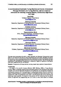
Design and Testing of a One Dimensional Measuring Machine for Determining the Length of Ball Bars John Ziegert, David Rea Department of Mechanical Engineering University of Florida Gainesville, FL 32611 Steven D. Phillips, Bruce Borchardt, John Stoup National Institute of Standards and Technology Gaithersburg, MD ABSTRACT A new machine for the rapid calibration of ball bars has been built. By means of comparisons to CMM measurements, it has been shown to work as an accurate special purpose machine for the calibration of ball bar lengths. INTRODUCTION One of the most common artifacts used to evaluate the volumetric measuring performance of coordinate measuring machines is the ball bar (ANSI/ASME B89.1.12M). This procedure involves measuring the distance between two precision spheres held a fixed distance apart by the connecting rod of the ball bar. The measurement is repeated at numerous positions and orientations in the workzone of the machine. Because the ball bar is a fixed length, any measured deviations in the ball bar center-to-center length indicate measuring errors of the CMM. When used for this purpose, the absolute length of the ball bar need not be known. However, more information about the CMM can be gained by examining the measurement errors using a calibrated length ball bar. The current best method for calibrating the length of ball bars is by measurement on very high performance CMMs. This procedure is expensive and time consuming, and is unsuitable for adoption by individual corporate standards laboratories. The goal of the work reported here is to provide a simpler and lower cost instrument capable of measuring the absolute length of ball bars ranging from 300 to 1000 mm nominal length with an expanded uncertainty for the measurement of U = 0.2 µm + 0.2 L µm, where L is given in meters. An additional goal is to design an instrument which does not act as a length comparator, thus requiring a calibrated ball bar to “master” the instrument, but introduces the length metric directly into the measurement process. DESIGN CONCEPT The instrument we have developed is essentially a 1 dimensional measuring machine (1DMM). It is composed of a long stiff granite beam (approx. 150mm X 300mm X 2000mm) with 2 air bearing stages riding on its top surface (Figure 1). Each stage carries a kinematic mount to accept the end of a ball bar, and a retroreflector mounted so that its center is coaxial with the axis of the ballbar, minimizing Abbe errors during measurement. A fixed block at the center of the beam holds another kinematic mount to accept a ball bar end. A metrology frame is kinematically mounted to the top of the granite beam. The metrology frame consists of two endplates connected by 3 Invar rods. Each endplate of the metrology frame holds a
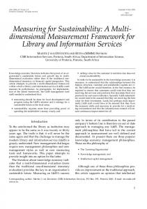
Michelson interferometer whose measurement axis is aligned with the ballbar axis and stage motion, thus minimizing cosine errors. (Figure 2) The granite beam is sized so that deflections due to the weight of the ball bar and the moving sled cause negligibly small errors in the measurements. Appropriate adjustment degrees of freedom are provided on the sleds and optical mounts to allow the three kinematic mounts to be aligned in a straight line and the interferometer beams to be aligned to the stage motions.
Figure 1. Conceptual design of 1DMM
Figure 2. Interferometer layout of 1DMM
The measurement procedure is as follows: 1. Place the ball bar ends in the kinematic mounts on the left movable stage and fixed center point and initialize the left interferometer to zero. 2. Move the right end of the ball bar to the right movable stage, and simultaneously initialize the right interferometer to zero and record the displacement, a, measured by the left interferometer. 3. Move the left end of the ball bar to the fixed center mount and record the displacement, b, of the right interferometer. 4. The length between ball centers of the ball bar is L = a + b. UNCERTAINTY ANALYSIS In the design stage, we generated an uncertainty analysis based entirely on Type B uncertainties. This analysis takes into account laser system errors, environmental effects, stage misalignments and error motions, cosine and Abbe errors of the measurement beam, thermal effects in the ballbar and metrology frame, sag of the ball bar, and mechanical repeatability of the system. (Table 1) The assumed measurement conditions for the uncertainty analysis are: 1. Room at 20 °C ± 0.05 °C. 2. Temperature of air and ballbar measured to ± 0.01 °C. 3. Barometric pressure measured to ± 0.255 mm Hg (34 Pa). 4. Relative humidity measured to ± 5%. 5. Uncertainty of Coefficient of Thermal Expansion (CTE) of material = 1 x 10⁻⁶ /°C.
6. 7. 8. 9.
Negligible vibrations. Dead path length for each interferometer = 10 mm. CO2 content of atmosphere = 355 x 10-6 Time required for complete measurement is assumed to be less than 10 minutes.
Table 1. Uncertainty analysis for a 1000 mm ballbar measurement. Wavelength stability Polarization mixing Resolution Environmental Error
0.027 0.00164 0.00124 0.161
Deadpath Error
0.001
Stage Misalignment
0.02
Laser Alignment
0.007
Thermal Errors
0.176
Ball Sphericity
0.1
Ball Bar Sag 0.07 Combined Standard Uncertainty: uc = 0.270 µm Expanded Standard Uncertainty: U = 2 uc = 0.540 µm Target Expanded Standard Uncertainty: U = 0.400 µm
Although the uncertainty analysis shows that the target expanded uncertainty is not met, it can be seen that the most significant contributors to the error are environmental and thermal effects. Changes in the basic design of the machine will have a small effect on these sources of error. Therefore, it was decided to build and test a prototype 1DMM to assess its accuracy and repeatability. TEST RESULTS Figure 3 shows a photograph of the prototype 1DMM. The instrument was delivered to NIST and assembled in a room with the temperature controlled to approximately ± 0.05 ˚C. The temperature, pressure, and humidity of the air were monitored and appropriate corrections to the index of refraction were made using Edlen’s equation. The temperature of the ball bar was also monitored and its length corrected using the best available estimate of the CTE. Noise and drift tests were performed to assess the stability of the instrument and to determine the optimal sampling time for interferometric measurements. Based on these tests, it was decided to read the laser interferometers by sampling them 150 times over a 15 second period and averaging the readings. This procedure was selected to reduce the sensitivity of the measurements to variations in the air along
the laser path due to imperfect mixing of the air in the room, yet still be rapid enough to minimize the effect of thermally induced changes in the instrument components. Six ball bars of varying lengths and materials were measured by NIST on a Moore M-48 CMM. These ball bars were then measured on the 1DMM. Each ball bar was measured 10 times on the 1DMM, which required approximately 30 minutes. The measured length of the ball Figure 3. Prototype 1DMM
bar is reported as the mean of the 10 measurements. Table 2 shows the results of these measurements. Table 2. Results of 1DMM measurement of 6 ball bars. (All lengths in mm) Ball bar Nominal 1DMM 1DMM CMM measured 1DMM length – material length length 2*S.D. length CMM length Steel 400 400.54437 0.00020 400.54454 -0.00017 Invar 400 400.09760 0.00017 400.09759 0.00001 Invar 500 499.93388 0.00030 499.93403 -0.00015 Invar 600 599.98659 0.00021 599.98635 0.00014 Steel 700 698.90277 0.00015 698.90290 -0.00013 Invar 900 899.93887 0.00025 899.93857 0.00030 In all cases the 1DMM measurements were within 0.30 µm of the CMM measured lengths. The expanded uncertainty of the CMM measurements (k = 2) is 0.2 µm + 0.2 L µm (L in meters). Two standard deviations of the 1DMM repeatability were all less than or equal to 0.30 µm, which is significantly less than predicted by the uncertainty analysis of Table 1, and is most probably due to better environmental conditions than were assumed in that analysis. Furthermore, in all cases the 1DMM-CMM differences for these measurements are less than the target value established at the beginning of the project. The 1DMM achieves satisfactory results as a special purpose machine for highly accurate certification of the length of ball bars at a small fraction of the cost of high accuracy, general purpose CMMs. References 1. ASME B89.4.1M-1997. Methods for Performance Evaluation of Coordinate Measuring Machines, ASME, New York, 1997. 2. Edlen, B. The Refractive Index of Air, Metrologia, Vol. 2, No. 2. 71-80. 3. Estler, W. Tyler. High-accuracy displacement interferometry in air, Applied Optics, Vol. 24, No. 6., 15 March 1985. 808-815. 4. Phillips, Steven D., Borchardt, B., Doiron, T., Henry, J. Properties of Free-Standing Ball Bar Systems, Journal of the American Society for Precision Engineering. Vol. 15, No. 1, January, 1993. 16-24. 5. Slocum, A. Precision Machine Design. Prentice-Hall, Inc., Englewood Cliffs, NJ, 1992. 6. Taylor, Barry N., Kuyatt, Chris E. Guidelines for Evaluating and Expressing the Uncertainty of NIST Measurement Results, NIST Technical Note 1297. U.S. Government Printing Office, Washington, DC, 1994. 7. Rea, L.D., “Design, Assembly, and Testing of a Ball Bar Measuring Machine”, MS Thesis, University of Florida, August 2001. 8. Certain trade names and company products are mentioned in the text or identified in illustrations in order to adequately specify the experimental procedure and equipment used. In no case does such identification imply recommendation or endorsement by National Institute of Standards and Technology nor does it imply that the products are necessarily the best available for the purpose.