Design, development and testing of Wireless Sensor Network Mote Sachin Gajjar
Nilav Choksi
Mohanchur Sarkar
Kankar Dasgupta
Institute of Technology, Nirma University, Ahmedabad, Gujarat, India.
[email protected]
Institute of Technology, Nirma University, Ahmedabad, Gujarat, India.
Space Application Centre, Indian Space Research Organisation, Ahmedabad, Gujarat, India.
Indian Institute of Space Science and Technology, Thiruvananthapuram, India.
Abstract— Wireless Sensor Networks (WSN) have enormous potential because they expand human ability to monitor and interact remotely with the physical world. Smart sensor nodes called motes can collect huge amount of hitherto unknown data for a whole new class of computing applications. Nevertheless, to exploit the potential of WSN, it is required to address peculiar limitations of these networks and resulting technical issues including the mote design. To meet this trend, this paper presents design and development of an ultra-low power mote (ULPM) using TI’s MSP430F5132 microcontroller, CC2500 transceiver chip from TI and HTU21D relative temperature and humidity sensor from Measurement Specialties Inc. The design flow starting with component selection and followed by schematic design, PCB layout, hardware development, programming and testing is presented in the paper. Next, a comparative analysis of ULPM with Mica2/Micaz, TelosB/Tmote, SHIMMER, IRIS, Sun SPOT, EZ430-RF2480/F2500T and Waspmotes is presented. Finally simulation of LEACH protocol for all the motes is carried out. Analysis of network lifetime, data transmitted and energy consumption shows that ULPM outperforms its counterparts. Keywords— WSN motes; mote hardware design; mote development and programming; mote testing; LEACH simulation
I. INTRODUCTION WSN applications range from simple data gathering, environment monitoring to complex ones like Internet of Things [1]. For all applications the physical design space consists of hardware subsystems like processing element (to run network protocols), transceivers (for wireless communication), sensors (to collect environmental date), memory, power source and software subsystems like middleware (to shield software from machine-level functionality), sensor drivers (to shield application programs from machine-level functionality of sensor), communication drivers (to manage minutia of radio). The entire package is of typically two cubic inches size. These devices called motes run energy efficient protocols, sleep most of the time, intermittently collect data and send it to Base Station (BS). They are densely deployed in an unattended hostile environment where they may technically fail, decease due to shortage of power or be materially damaged. This requires the mote to be low in power consumption and cost, small in size, non-obtrusive, self-managed, reprogrammable and available all the time. This paper presents a low power, low cost, selfmanaged, reprogrammable and robust mote called ultra-low power mote (ULPM). The rest of the paper is organized as follows: Section 2 presents commercially available motes. Section 3 presents design and testing of ULPM. Section 4
gives comparative analysis of ULPM with seven commercial motes. Section 5 Simulation of LEACH protocol using all the motes. Finally, paper is concluded in Section 6. II. COMMERCIAL MOTES A number of research institutions and companies have been designing and producing motes for various WSN applications. This section presents some of the most popular motes. • Mica2/Micaz from CrossBow Technology [2] come with expansion sensor boards including humidity, temperature, light, pressure to connect directly to mote. There is interface support for actuators like relays and buzzers. However, the entire design is hardware concentrated. • TelosB/Tmote Sky are developed by University of California, Berkeley and currently available from MEMSIC Inc [3]. It supports adhoc mesh networking. However, its design is hardware concentrated and ignores software optimizations. • SHIMMER, the Sensing Health with Intelligence, Modularity, Mobility, and Experimental Reusability is designed by Real-time Technologies [4] for wearable health sensing. It supports Bluetooth radio modules and has real time communication capability but lacks robustness. • IRIS are from Crossbow Technology with 3-times radio range compared to MICA motes and half power consumption. However, it has less number of on board sensors. • Sun SPOT are Small Programmable Object Technology from Sun Microsystems [5]. They provide open source hardware and software support but are expensive. • EZ430-RF2480/F2500T are wireless networking solutions from Texas Instruments [6]. They are lowest in cost and size and best suited for applications requiring large scale deployment and sensor data from external source(s). • Waspmotes are open source hardware and software sensor platform from Libelium Comunications [7]. It has built in micro SD card interface with up to 2 GB support, gives solar powering option and 8 types of radio support. However, the hardware design is too complex. III.
ULPM DESIGN AND TESTING
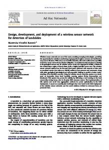
A. Hardware Subsystem: The hardware block diagram of ULPM is shown in Fig. 1. It consist of TI’s MSP430F5132 [8] microcontroller as processing element, TI’s CC2500 [9] as transceiver and HTU21D [10] sensor for relative humidity and temperature measurements from Measurement Specialties Inc. • Processing element: MSP430F5132 is the latest ultra-low power controller from TI’s MSP430 family with six low
Figure 1: Hardware components of ULPM
power modes suitable for power saving in motes. It has a 16bit RISC CPU, 16-bit registers and constant generators for high code density a feature required in motes due to their limited storage capability. The digitally controlled oscillator allows wake up from low-power modes to active mode in less than 5 µs to meet real time requirements of WSN applications. The spy-by-wire and 32KB flash supports remote programming and debugging of the mote. 40 pin QFN package decreases the overall size of the mote. Watchdog timer helps to detect software anomalies to make the mote robust. SPI and I2C interface are used to attach CC2500 transceiver and HTU21D sensor. The UART interface is used to connect mote with computer. 29 GPIOs and 8 ADC channels can be used to attach various sensors and actuators. • Transceiver: The CC2500 supports data transmission at 2.4 GHz (licence free ISM band) using any of the modulation techniques like GFSK/MSK/OOK. Support for data buffering, burst mode transmission (with separate 64-bytes receive and transmit data FIFOs), automatic clear channel assessment, link quality indication, manchester coding, programmable data rate (1.2 to 500 kbaud), digital RSSI output, programmable carrier sense indicator can be used for efficient protocol design. High sensitivity (104 dBm at 2.4 kbaud, 1% packet error rate), programmable output power up to +1 dBm, excellent receiver selectivity and blocking performance, programmable preamble quality indicator (for protection against false sync word detection in random noise) helps to create reliable communication links between motes. Low current consumption (13.3 mA in receiving at 250 kBaud, 400 nA in sleep mode), wake-on-radio functionality for automatic lowpower receiver polling makes it suitable for low power mote design. Support of frequency hopping and multichannel systems with help of fast settling frequency synthesizer (90 µs settling time), programmable channel filter bandwidth helps reduce interference and provide secure communication. Onchip support for sync word detection, address check, flexible packet length, and automatic CRC handling helps to create secured communication links. With SPI interface it can be easily interfaced with a large range of controllers. Fast start up time of 240 µs from sleep to receive or transmit mode makes it suitable to meet real time requirements of WSN applications. • Sensor: HTU21D, a digital relative humidity and temperature sensor from Measurement Specialties Inc. is embedded in a reflow solderable DFN package of 3x3 mm foot print and 0.9 mm height which makes mote design compact. It provides calibrated, linearized signals for temperature and humidity measurements directly in digital, I2C format which makes it easy to interface and program. It is a low power device requiring supply voltage between 1.8 to 3 V and has energy saving modes. Its resolution can be
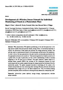
changed by command, can detect low power supply conditions and provides checksum for reliable communication with the controller. It is compatible with automatized assembly processes including Pb free and reflow processes. • Schematic design: The schematic design of ULPM shown in Fig. 2 (after References section) is developed in Orcad electronic design automation (eda) software tool from Cadence [11]. Crystal is of 26 MHz and maximum supply voltage is of 3 V. CC2500 is interfaced with MSP430 through SPI interface. Capacitors and inductor at pin RF_P and RF_N form a balun for impedance matching. Component values for the RF balun and LC network are found using SmartRF studio from TI [12]. HTU21D sensor is interfaced with MSP430 through I2C interface. Next the design rule check is carried out followed by netlist and bill of materials generation for ULPM. • PCB layout: The PCB layout shown in Fig. 3 is carried out in Cadstar tool from Zuken [13]. To reduce the mote size two layer PCB is designed. The board layout is 65.90 mm x 45.70 mm with 2 AAA battery socket. The gerber files and reports are generated using extended gerber RS274-X format [14]. B. Software subsystem: The ULPM software stack is in Fig. 4. The topmost layer is application layer consisting of: (i) files for programming UART for connecting the mote to computer; (ii) product interface files for programming CC2500 (for initialization, send, packet, and receive packet) and HTU21D (for receiving data and sending acknowledgement). The next layer is software library layer consisting of: (i) header files with declaration of functions in product interface files (TI_CC_SPI.h for CC2500 and HS_I2C.h for HTU21D); (ii) files with functions for accessing CC2500 registers through SPI and HTU21D registers through I2C interface (TI_CC_SPI.c for CC2500 and HS_I2C.c for HTU21D). The bottommost layer is hardware definition which consist of: (i) hardware abstraction files (Hardwareboard.h) which has board specific functions like hardware pin connections between MSP430F5132, CC2500 and HTU21D, (ii) TI_CC2500.h and HS_I2C.h consist of function declaration for product interface specific files TI_CC2500.c and HS_I2C.c. The software stack is coded in C language using IAR Embedded workbench [15].
Figure 3: PCB Layout of ULPM
Figure 5: Software architecture of ULPM Figure 4: Software stack of ULPM
C. ULPM Testing The software architecture of mote is shown in Fig. 5. The controller is in the sleep mode for most of the time to save power. Timer is programmed to interrupt and wake up the controller at regular intervals of time. On wake up the microcontroller sends commands to humidity sensor to collect sensor data. On receiving sensed data, microcontroller processes it and then commands transceiver to transmit processed data. The microcontroller turns off the transceiver and the sensor after the transmission is over and itself goes to sleep mode till the next cycle. Temperature testing of ULPM was carried out by keeping the mote in different environments like refrigerator, living hall, kitchen and near a room heater. Humidity testing was done for one day from 10:00 hours in the morning to 16:00 hours in the noon. Fig. 6 and 7 show that there is ±2% error in actual values and those measured and transmitted by ULPM. IV.
Figure 6: Temperature measurements
COMPARATIVE ANALYSIS
Table 1 provides qualitative comparison of ULPM with seven popular motes. The parameters used for comparison include: physical dimensions, weight, size, operating temperature range, battery capacity, year in which they are introduced, manufacturing company and cost. As seen in the Table 1 ULPM is cheapest and smaller is size compared to most of the motes. Table 2 provides a detailed comparison of computational and storage logic of the motes. As seen in the Table 2, ULPM has least wake up time making it a good choice for real time WSN applications. Further, its current consumption is least in active mode compared to all the other motes. Its current consumption in the standby mode is also low compared to most of the motes. Power consumption of ULPM is least in active mode and comparatively less than most of the motes in sleep mode. ULPM can be programmed using Tiny OS [16] or in C using TI’s Code Composer Studio [17] or IAR Embedded workbench. Table 3 shows the radio modules used in the motes and on board sensor support offered by the motes.
Figure 7: Humidity measurements
V. SIMUATION OF LEACH PROTOCOL The performance analysis of ULPM and the popular motes is carried out through simulation. Low Energy Adaptive Clustering Hierarchy (LEACH) protocol is used for simulation. LEACH is a well referred protocol architecture that uses a hierarchical approach and organizes the network into a set of clusters with a cluster head administering the cluster [18]. The cluster head is responsible for: creating a TDMA-based transmission schedule for its cluster members,
aggregating the data collected from its cluster members and transmitting it to BS. • Simulation and Results Simulations are carried out in Matlab [19]. The simulation parameters are shown in Table IV. To reduce occasionalism, thirty simulations with different seeds were carried out for each network scenario and mean values were taken as results. TABLE IV SIMULATION PARAMETERS
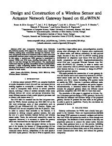
Figure 8: Total residual energy of the network over rounds
The energy for radio electronics, data aggregation and radio amplifier are taken based on respective node’s specifications. The motes begin with an unlimited amount of data to be periodically sent to BS. Fig. 8 shows sum of residual energy traced at an interval of 100 rounds. As seen in the figure, ULPM is the most energy efficient mote. This is because MSP430F1611controller consumes the least amount of power in its active and sleep modes and can be operated in six low power modes. The deepest sleep mode, LPM5 consumes only about 2.7 µW. During the active mode microcontroller consumes 0.18 mW which is 33% less power consumed by controller used in EZ-F2500T. As the simulation progresses, motes use up their energy and are said to be dead when they cannot transmit or receive data from nodes within its neighbourhood. The total number of motes that die during the simulation rounds is shown in Fig. 9. Since the overall energy consumption in ULPM is minimum the number of dead motes is also least. The performance requirements of WSN largely depends on the applications for which it is deployed. For example, a WSN for environmental monitoring requires energy efficient nodes to avoid battery recharge/replacement. On the other hand, intrusion detection application stresses on reliable and timely data delivery. Thus merit of mote is application-specific measure. However, one application independent technique of defining merit of mote is to determine total amount of data packets delivered to the BS. The investigation of the sensing field will be more detailed if more data is received at the BS. Fig. 10 presents total aggregated data packets delivered by the motes to BS. It shows that ULPM delivers maximum packets. This is because the number of dead motes is minimum in the case of ULPM.
Figure 9: Number of nodes dead over rounds
Figure 10: Total amount of data received at the BS over round
VI.
CONLUCSION
This paper presents design and development of ULPM mote using MSP430F5132 micro-controller, CC2500 transceiver,
HTU21D relative temperature and humidity sensor. The mote was designed by Cadence and Cadstar tools and programmed in C using IAR workbench. Experimental results for humidity and temperature measurements of ULPM shows that there is ±2% error in actual values and those measured and transmitted by ULPM. Simulation of LEACH protocol using ULPM and seven other motes shows that ULPM shows best performance in terms of network lifetime, data transmitted to BS and energy consumption of the network. REFERENCES [1] S.H. Gajjar, S.N. Pradhan, K.S. Dasgupta, “Wireless Sensor Networks: Application led research perspective”, Proc. of IEEE Recent Advances in Intelligent Computational Systems, pp. 25-30, 2011. [2] Moog Crossbow Technologies Wireless Sensor Network prodcucts [Online] Available: http:// www.xbow.com. [3] MEMSIC Inernaltional corporation Wireless Sensor Network products [Online] Available: http://www.memsic.com/. [4] Realtime Technologies Wireless Sensor Network products [Online] Available: http://www.realtime.ie/. [5] Project Sun SPOT [Online] Available: http://www.sunspotworld.com. [6] EZ430 guide [Online] Available: http://www.ti.com/tool/ez430-rf2500.
[7] Libelium Communications waspmote catalogue [Online] Available: http://www.libelium.com/products/ waspmote/. [8] Texas Instruments, MSP430F51x2 datasheet, [Online] Available: http://www.ti.com/product/msp430f5132. [9] Texas Instruments, CC2500 datasheet [Online] Available: http://www.ti.com/product /cc2500. [10] Measurement Specialties, HTU21D datasheet, [Online] Available: http://www.meas-spec.com/downloads/HTU21D.pdf. [11]Orcad Tools [Online] Available: http://www.cadence.com/products/orcad [12] Smart RF studio [Online] Available: www.ti.com/tool/smartrftm-studio [13]Cadstar Tools [Online] Available: http://www.zuken.com/cadstar. [14]Gerber files [Online] Available: http://www.eurocircuits.com/pcb-layout [15]IAR Embedded workbench [Online] Available: http://www.iar.com/ServiceCenter/Downloads/. [16] TinyOS guide [Online] Available: http://www.tinyos.net/. [17] Code composer studio IDE Tools from Texas Instruments [Online] Available: http://www.ti.com/tool/ccstudio. [18]W. B. Heinzelman, A. P. Chandrakasan, H. Balakrishnan,”An Application Specific Protocol Architecture for Wireless Microsensor Networks”, IEEE Transactions on Wireless Communications, vol. 1, no.4, pp. 660-670, 2002. [19]MATLAB guide [Online] Available: http://www.mathworks.in/.
Figure 2: Schematic design of ULPM
TABLE I QUALITATIVE PARAMETERS OF MOTES
TABLE II COMPUTATIONAL, STORAGE LOGIC AND SOFTWARE SUPPORT OF MOTES
*
TOS=Tiny OS Cross development tools with TOSSIM Simulator, AT=ATMEL
TABLE III RADIO MODULES, ON BOARD SENSORS OF MOTES
*
T= Temperature, H=Humidity, L=Light, A=3-axis accelerometer, C=CHIPCON, AT=ATMEL