Development of an Intelligent Wireless Sensor Network with Mobile Nodes Joseph St. Pierre and Howard E. Michel* Electrical & Computer Engineering Department, University of Massachusetts Dartmouth, North Dartmouth, MA, USA 02747 ABSTRACT Wireless sensor networks have become viable solutions to many commercial and military applications. This research focuses on utilizing the I-TRM to develop an architecture which supports adaptive, self-healing, and self-aware intelligent wireless sensor networks capable of supporting mobile nodes. Sensor subsystems are crucial in the development of projects to test complex systems such as the Future Combat System, a multi-layered system consisting of soldiers and 18 subsystems connected by a network. The proposed architecture utilizes the Sensor Web Enablement (SWE), a standard for sensor networks being developed by the Open Geospatial Consortium (OGC), and the Integrated Technical Reference Model (I-TRM), a multi-layered technical reference model consisting of a behavior-centric technical reference model, information-centric technical reference model, and control technical reference model. The designed architecture has been implemented on MPR2400CA motes using the nesC programming language. Preliminary results show the architecture meets needs of systems such as the Future Combat System. The architecture supports standard and tailored sensors, mobile and immobile sensors nodes, and is scalable. Also, functionality was implemented which produces adaptive, self-healing, and self-aware behavior in the wireless sensor network. Keywords: wireless sensor networks, technical reference model, Future Combat System, test and evaluation
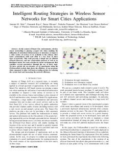
1. INTRODUCTION With advances in technology, wireless sensor networks have become a viable solution to many commercial, environmental, and military applications. To meet the needs of these applications, standards and robust architectures must be developed which provide effective solutions that can be integrated into existing systems or used to create appliqué systems for test and evaluation. Architectures supporting adaptive, self-healing, and self-aware intelligent wireless sensor networks must be designed. Such architectures are needed for testing systems such as the Future Combat System (FCS). The FCS is a family of manned and unmanned systems which are connected by a common network [1]. One piece of these systems will be a heterogeneous sensor subsystem with mobile nodes. Command and control vehicles (C2V's), unattended ground sensors, soldiers, and small unmanned ground vehicles will be parts of this subsystem are shown in Figure 1. C2V's are large manned armored vehicles which can act as the base station of the wireless sensor network. The C2V's can receive information from unmanned ground vehicles (cluster heads) which gather data from sensors on soldiers and unattended ground sensors. Sensors on soldiers require that the sensor network can dynamically adapt to changing topologies.
Unattended Ground Sensor (Immobile Node) Soldier with Sensors (Mobile Node) Simuiled Unmanned Ground Vehicle (SUGV) (C1usterhtad) Basestation) Figure 1, FCS Sensor Subsystem
*
[email protected]; phone +1 508 910 6465; fax +1 508 999 8489
Intelligent Sensing, Situation Management, Impact Assessment, and Cyber-Sensing, edited by John F. Buford, Gabe Jakobson, Stephen Mott, Michael J. Mendenhall, Proc. of SPIE Vol. 7352 73520K · © 2009 SPIE · CCC code: 0277-786X/09/$18 · doi: 10.1117/12.818874 Proc. of SPIE Vol. 7352 73520K-1
Current technical reference models used to develop architectures are too specific to meet the needs of researchers in the wireless sensor network domain. Technical reference models such as the OSI-ISO and SOA reference models focus only on a specific part of a system[12-14]. A technical reference model, the I-TRM, developed at the University of Massachusetts at Dartmouth, describes systems in terms of behavior, information, and control [2-7]. The goal of the ITRM is to provide a framework for developing architectures which can be adaptive, self-healing, and self-aware. This paper focuses on developing an architecture which adheres to the I-TRM, utilizes current standards, and meets the testing needs of the Future Combat System.
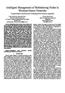
2. SENSOR WEB ENABLEMENT (SWE) AND PROPOSED ARCHITECTURE The proposed architecture utilizes the Sensor Web Enablement (SWE) web services and standards. The SWE provides a standard way to discover sensors, access sensors, command sensors, and receive sensor alerts. The services utilize standard, XML-based encoding which describe sensors and their data. The SWE consists of three standards and four services as described briefly below and as shown in Figure 2. [8]
SPS: Sensor rIsnnin SeILce SAS: Sensor Alert SeMce WFJS: Web Nocation Seriice SOS: Sensor Ohseiiation Sece AM: Asset Manager
Application/Client
+
+
SAS
WNS
SPS
DP: Dt Producer
Basestation
SOS
+
H
AM
DP
Sensors
Clusterhead
rvlote
Figure 2, Sensor Web Enablement
2.1 SWE Observations and Measurements Schema and Sensor Markup Language Observations and Measurement (O & M): O & M is an XML-based encoding standard defining observations and measurements of sensors. The OGC defines an observation as an event that produces a resulting measurement and a measurement is defined as a value and the units of the value. Thus, the O&M's primary purpose is to link raw data obtained from a sensor at a given time (event) with scaling and units. Metadata is also attached to provide information concerning the circumstances of a sampling event. Sensor Markup Language (SensorML): SensorML is an XML-based encoding standard for describing sensors/sensor systems and processes associated with sensor observations. SensorML provides information needed for discovery of sensors, location of sensor observations, processing of low-level sensor observations, and listing of taskable properties, as well as supports on-demand processing of sensor observations.
Proc. of SPIE Vol. 7352 73520K-2
2.2 SWE Services Sensor Observation Service (SOS): The SOS provides the interface between the sensors and the world. The SOS utilizes the O&M and SensorML standards to communicate these observations to the other components in the SWE. The SOS contains SensorML processes for the different types of sensors and/or sensor systems in the network. The Sensor Observation Service's primary goals are transmitting commands to the sensor network, receiving and transforming data from the sensor network, and providing this data along with necessary metadata to the Sensor Planning Service (SPS) and User via the Observation & Measurements standard. Sensor Planning Service (SPS): The SPS manages the goals of the system. The SPS specifies standard interfaces for requesting capabilities, requesting the status of a goal, and canceling or updating the goal. It determines the feasibility of a goal, whether it is accepted or not, and based on feedback from the sensor network, makes any needed adjustments to the goals of the system. Web Notification Service (WNS): The WNS was designed to allow asynchronous sending and receiving of notifications. Based on the system goal/event requests and data from the sensor network, the WNS notifies the user of events of interest occurring within the environment of the sensor network or the network state. Sensor Alert Service (SAS): The SAS is a standard web service interface for publishing and subscribing to alerts from sensors. This notification occurs through the WNS. 2.3 Other SWE components The Asset Manager (AM) identifies, uses, and manages available information sources. It is broken up between cluster heads managing motes and motes managing their sensor(s). At the cluster head level, the AM is responsible for transforming the standard XML encoding generated by the SPS to functional tasks. This provides a separation between the standard SWE interface and the hardware and software requirements of the cluster heads, motes, and sensors. It performs these responsibilities based on information received from the Data Producer (DP). At the mote level, the AM gathers and stores sensor data. At the cluster head level, the Data Producer is responsible for generating simple XML insert documents that can be published to the SOS. These XML inserts contain sensor data and metadata. The Data Producer also provides a separation between the SOS client and the hardware and software requirements of the cluster heads, motes, and sensors. At the mote level, the Data Producer is responsible for transmitting sensor data and metadata to the cluster head for further processing. The base station is responsible for the higher level functionality of the system and includes the SPS, SOS, WNS, and SAS as well as utilizes the SWE standards (SensorML and O & M). The SensorML documents for the sensors in the network are utilized in the SOS. Data received from the Data Producer are scaled and units defined based on the metadata defined in the sensor's SensorML document. The SOS is responsible for generating Observation and Measurement XML documents which can be delivered to the application/client based on the goals and alerts defined in the SPS and SAS. The SensorML and Observation and Measurements documents are also used by the SPS for making goal decisions.
3. I-TRM AND THE PROPOSED ARCHITECTURE The Integrated Technical Reference Model (I-TRM), depicted in Figure 3, consists of three, six-layered TRMs—Control (C-TRM), Information-Centric (IC-TRM) and Behavior (B-TRM). The goal of the I-TRM is to provide a guideline for the architectures to be developed which can decompose high-level goals into low-level tasks based on current requirements and system capabilities, and on information about the environment and state of the system. The success of the goal can be determined by the layers of the C-TRM through feedback from the B-TRM, which receives information concerning the state of the system and environment from the IC-TRM. The specific task distribution and execution may change based on this feedback received. This provides a means to achieve goals more efficiently and effectively. In a classic control system, the output consists of an input value combined with a scaled version of the output. A modified feedback system was developed to manage the three TRMs. By combining these three technical reference models into the control loops shown in Figure 4 a complete system can be defined which can intelligently suggest and execute decisions based on its level of knowledge. The modified control system provides feedback horizontally across
Proc. of SPIE Vol. 7352 73520K-3
the three TRMs. The following sections describe each technical reference model and its layers as they will relate to the proposed architecture.
Physical
B-TRM Figure 3, Integrated Technical Reference Model
3.1 The Information Face The information-centric technical reference model (IC-TRM) describes obtaining, scaling, aggregating, and transforming data into knowledge for presentation. The physical and data layers gather and authenticate large amounts of raw data. The Information Layer scales this raw data and correlates it with location, measurement units, and other metadata to produce information about the system and environment. Since each mote only possesses information about the system and environment within a very specific part of the network, to gain an overall view of the environment and system requires all the individual motes' data be aggregated. This is accomplished in the Aggregation Layer, where goaldirected fusion of data from the motes produces information about the total environment and system. This information is then transformed into knowledge based on intrinsic, extrinsic, and current available knowledge. This knowledge is presented in the Application Layer based on the user's preferences.
Figure 4, Control Loops in the Integrated Technical Reference Model
Proc. of SPIE Vol. 7352 73520K-4
3.2 The Control Face The control technical reference model (C-TRM) defines execution from high-level user goals to low-level task execution on motes and cluster heads. The user interfaces with the wireless sensor network to define goals through the Application Layer of the C-TRM. The defined goals are authenticated and their feasibility is determined in the Validation Layer. The goal is either accepted or rejected in this layer based on a calculated probability of success. Once the high level goal is accepted, it must be broken down into tasks which the motes and cluster heads can execute. This is accomplished in the Translation Layer, where task decomposition is based on lower layer information obtained from the IC-TRM. These tasks are further broken into prioritized subtasks in the Distribution Layer based on the mote's system resources and capabilities. Finally, the Execution Layer works directly with the Physical Layer to generate control signals resulting in subtasks being executed in accordance with higher layers requests. 3.3 The Behavior Face The behavior technical reference model (B-TRM) provides the actual feedback in the system. It manages the intelligence of the wireless sensor network by managing the communication between hierarchically equivalent layers of the IC-TRM and C-TRM. The Application Layer of the B-TRM is responsible for managing what, when, and where information should be presented as well as what goals should be accepted. For the Validation Layer to function effectively, it needs information from the Knowledge Layer. The Conscious Behavior Layer defines strategies for taking care of deliberate actions and checking a goal's validity based on relevant information in the Knowledge Layer. The Reactive Behavior Layer provides methods for transforming a high-level goal into tasks. For effectiveness, these methods must incorporate information from the Aggregation Layer such as mote capabilities and resources. In the three lowest behavior layers, purely reactive behavior furnishes the relevant data for task execution from the IC-TRM layers to the C-TRM layers. 3.4 Three Layer Architecture The architecture is composed of three layers: the Base Station, a series of Cluster Heads, and numerous Sensor Nodes. Figure 5 shows how the layers of the I-TRM are separated among the different components of the architecture. The Base station: The base station is responsible for all higher level functionality in the system. It is in the Information Layer that the raw data obtained from the sensors is transformed into a scaled value with units based on knowledge of the sensor in SensorML documents. This transformed information from various sources is then combined in the Aggregation Layer based on the goals/functional tasks of the system. The Reactive Layer provides the Aggregation Layer with knowledge of these goals and supplies the Translation Layer with aggregated, scaled data, system state, and knowledge of lower level components which it utilizes to transform goals into functional tasks. The aggregated data is further transformed in the Knowledge Layer. Layers of I-TRM Utilized on Motes Data In
Application/Client Basic Innate Layer
Execution Layer
Physical Layer
Data Layer
Validation Layer
I Conscious Layer
Physical Layer
Translation Layer
I
t
Datt4put
Layers of l-TRM Utilized on ClusterHead Data In
Layers of l-TRM Utilized on Basestation
Distribution Layer
Reactive Layer
Datfi4Out
Knowledge Layer
+
Aggregation Layer
4
Information Layer
Distribution Complex Innate Information Layer Layer Layer
I
DatOut Figure 5, Relationships between I-TRM and the Architecture
The Cluster head: The cluster head provides an interface between the sensor network and the base station. The cluster head communicates with the base station through the SWE standard interfaces defined above, ensuring interoperability. It utilizes part of the Information Layer, the Complex Innate Behavior Layer, and the Distribution Layer. In the Distribution Layer, the cluster head determines which sensors or what sensor regions of its sensor community receive the functional tasks and the execution priority of functional tasks. The Complex Innate Behavior Layer provides the
Proc. of SPIE Vol. 7352 73520K-5
Distribution Layer with needed information from the Information Layer as well as updating the Information Layer on the state of the system. The Information Layer is responsible for sending the raw sensor data and metadata to the base station by generating simple XML insert documents for the Information Layer in the Base station. The Sensor Node: The sensor node utilizes the Basic Innate Behavior Layer, Execution Layer, Data Layer, part of the Distribution Layer, and the Physical layers. The mote receives functional tasks from the cluster head via the Distribution Layer and transforms them into subtasks that can be performed. The Basic Innate Layer passes needed data to and from the Data Layer to the Execution Layer for updating the system state and executing the subtasks, respectively. Finally the sensor node controls sensor data flow via the Data Layer. The SWE and I-TRM architecture views are combined in Table 1. Table 1, Relationships between Layer in the I-TRM and the SWE TRM
SWE Service/Interface
I-TRM layers
Sensor Planning Service (SPS)
Validation Layer Translation Layer
Sensor Observation Service (SOS)
Information Layer Aggregation Layer
Web Notification Service (WNS)
Knowledge Layer
Sensor Alert Service (SAS)
Validation Layer
Asset Manager (AM)
Distribution Layer Execution Layer
Data Producer (DP)
Information Layer Data Layer
Sensors
Physical Layer
Asset Manager and Data Producer Interface
Complex Innate Behavior Layer Basic Innate Behavior Layer
SPS and SOS Interface
Reactive Behavior Layer
SAS and WNS Interface
Conscious Behavior Layer
4. APPLIBILITY TO TEST AND EVALUATION OF THE FCS Consider a test scenario with 500,000 individual sensors, where commanders on the ground control test execution, not test directors, and where the test and evaluation (T&E) tasking is to report on the effectiveness of each weapon system, including the soldier in the loop. Further consider that you have only months to plan this test, and weeks to report the results. Such might be the situation when testing the Army’s Future Combat System in a force on force exercise. And simultaneously with this tasking you have the requirement to identify and report on any system, sub-system or component that has produced an anomalous response either as a result of previously unexperienced combinations of environmental conditions or random situations that had not been observed in previous testing. Clearly, the state-of-the-art in T&E for military systems today could not handle this tasking. What is required is a catalog of non-intrusive instrumentation—sensors, processors, storage devices, and software—to continuously monitor key parameters; accompanied by user friendly interfaces that can used to rapidly configure these components into a system for each test. Furthermore, if this system is to be cost-effective, it should be designed around modular components that are built with open interface standards for hardware, software and data and meta-data formats. If the system is to be robust, it needs to self-aware, self-healing and adaptable within a resource-constrained environment. We propose that T&E engineers consider a sensor network architecture built using the principals described above. The proposed architecture is implemented as a three-tiered hierarchy. The bottom tier consists of sensor nodes. The second tier is composed of cluster heads, and the third tier is composed of a base station. Sensor nodes are equipped with various sensors and are capable of performing basic networking, computing and sensing tasks. A group of sensor nodes
Proc. of SPIE Vol. 7352 73520K-6
are connected through a local one-hop network to a cluster head, the next tier level. Cluster heads are functionally more powerful units with more computational power, advanced data traffic and networking capabilities, and rich power resources for maintaining its one-hop communication with all subordinating sensor nodes and the root node. Cluster heads process data traffic and handle complex data processing to enrich the informational value associated with the data. The base station is at the top of this hierarchy. It is envisioned that each of these physical devices—sensor node, cluster head, and base station—implements one or more layers of the I-TRM described above. Each layer is thus a combination of hardware and/or software that can be specified through its interfaces, specifically its input and output data structures (data/meta-data, information/metainformation, knowledge, status, control and goal structures) and its ability to transform those data structures (behaviors). Commercial devices that span one or more layers could be built with companies differentiating their products by the implementations behind the open specification of the interfaces. This is already happening with the adoption of the IEEE-1451 family of standards for smart sensors. These smart sensors can implement the lower two or three layers of the I-TRM. An equivalent effort to standardize the upper layers of the pyramid would allow companies to develop and market software products to simplify or automate test set-up, operation and data interfaces. 4.1 Describing a hypothetical testing scenario Now consider a test and evaluation scenario in a force on force exercise of the Future Combat System. Consider the Application Layer for T&E in this exercise. The application layer is responsible for user interactions. It receives commands from the testers and produces reports. Commands issued to it might include a traditional tasking of reporting on the reliability of the engine in one of the vehicles. Other tasks might include reporting on the effectiveness in getting the relevant information to the commander in a timely manner or the effectiveness of troop training as measured by their ability to accomplish specified missions. Clearly these tasks become more complex as one shifts from purely mechanical measurements with firm performance parameters into factors that are more human dependant and subject to interpretation. In the near future these test reports would most likely be produced with a high level of human interaction in interpreting the data, but a properly defined sensor network architecture would allow the people generating these reports to easily interact with the system to “mine” the appropriate data. In this architecture, the Conscious Behavior, Knowledge, and Validation Layers support the Application Layer. This layer provides schemas for checking goal validity and feasibility in the given situation by checking goals against intrinsic and extrinsic knowledge (global model.).[9] It determines which goals should be accepted or not. It manages deliberate actions of the systems. In continuing our example, this layer would essentially perform a complete self-test when the system is powered up, and for example, report that all required hardware is operational and configured correctly, or possibly that the suggested synthetic instrument asked for could not be created because of limited bandwidth. In operation it would continuously assess the priorities of goals from the Application Layer, and pass them on to the lower layers or delay them depending on available resources. These goals could be simple goals such as reporting on the vibration levels in several vehicles, or very complex goals such as reporting on when combat information is delivered to a control center or when it was displayed and how much time the commander spent looking at it. This layer, and the Application Layer—the top two layers of the I-TRM—would probably be implemented in the base station due to the high computing requirements of these tasks. Below the Base Station, the sensor network would branch out into a series of Cluster Heads. A cluster head is a link between sensor nodes and the base station. It implements layer four of the I-TRM (or layer four could be implemented in the base Station) and is responsible for data aggregation and data consolidation. The Reactive Behavior, Aggregation, and Translation Layers provide a mechanism for dealing with information collaboration from various modules. It also provides procedures for translating goals into sub-modules in compliance with the state of the environment. This behavior requires a sophisticated understanding of the state of the various system sensors, and rules to interpret the goaloriented system tasking. This understanding and rules would be test-specific, but easily configured from more general rule prototypes. This layer could create virtual instruments that span either temporal or multi-sensor data streams. Software at this level would understand that is has various independent sources of data, from the known locations, that can be correlated to create the appropriate synthetic instrument. The software would also know how to react and re-task these sensors if priorities or system status changes, as might be the case if a sensor failed. At the lowest level of the architecture, sensor nodes will implement the bottom three layers of the I-TRM. The Complex Innate Behavior, Information, Distribution Layer is the highest of these three layers. It implements procedures that connect the information extracted from the data and meta-data passed up with task execution distribution passed down.
Proc. of SPIE Vol. 7352 73520K-7
Complex innate behaviors are composed of one or more basic innate behaviors structured in a predefined manner to produce a higher-level user-friendly interface. An example of a complex innate behavior might be to “continuously sample and stream data at a particular rate, gain setting, and filter characteristics.” Another complex innate behavior might be a self-calibration mode. The Basic Innate Behavior, Data, and Execution Layers implement primitive reflexive behavior and stimulus-response behaviors of the system. It combines the execution layer procedure-execution to produce the relevant data. In terms of smart sensors implied in the on-going example, one basic innate behavior would be to produce a data-word associated with a physical temperature. Another basic innate behavior would be to report meta-data when queried. Sensor data is created by calibrating transducer data. The Physical Layer consists of sensors and mechanical units. This layer executes actions as directed by higher layers and possesses no intelligence of its own. It gathers raw data in unformatted, unverified and transitory format. It deals with the electrical, mechanical and procedural characteristics of the system, including the working of transducers.
5. RESULTS The I-TRM Layers utilized in the motes were implemented on Crossbow MPR2400CA motes using the nesC programming language. These motes run on the TinyOS operating system which is designed specifically for wireless sensor networks. The MDA100CB sensor board is attached to each mote. These sensor boards contain a temperature sensor and light sensor. No actual testing was done on large-scale systems such as the FCS, nor was higher layer test software developed, however test results show that the architecture has promise. This architecture is capable of supporting both immobile and mobile nodes. The mote is the most resource constrained component within the wireless sensor network. Due to these limitation, it can only perform simple tasks. Its primary objective is transmitting retrieved sensor data to the cluster head. However, for a robust wireless sensor network, it must also be self-aware, knowing both its location and information about its neighborhood. Also, the network must be selfhealing, capable of detecting faulty motes and sensors. Finally, the network must be adaptable. Due to mobile motes, failing motes, and the changing environment, the network must be capable of maintaining connectivity. The following are the specific requirements the motes within this implemented network meet per the I-TRM and FCS. • Capable of breaking down a functional task into executable subtasks. A cluster head will know the capabilities of a mote and will send tasks which the mote is capable of executing. However, how the mote executes the tasks will depend on hardware specifications, prior tasks in the queue, etc. • Capable of prioritizing the subtasks and executing these accordingly. When breaking a task into subtasks, some subtasks may be required to execute before others. • Vary sample rate of individual sensors based on the state of the mote and tasks received from the cluster head. Depending on the need for particular sensor's data, high frequency sampling to no sampling may be required. • Capable of sending to a specific component in the network or broadcasting to everyone. • Capable of changing the listening/sending time and frequency. Radio activity consumes the largest amount of power for a mote so the capability of changing these parameters is paramount. • Maintaining a small history of data for each sensor attached. Sending clusters of data for every transmission reduces the overall radio activity and reduces power consumption. • The sensor motes maintain their location and a list of their neighbors. This ensures self-aware motes and allows the network to monitor connectivity • Detect faulty sensors by authenticating data. This ensures at least in part a self-healing network. • Attach and detach sensors. If a sensor is found to be faulty, then no more resources should be consumed sampling, storing and transmitting its data.
Proc. of SPIE Vol. 7352 73520K-8
6. CONCLUSION/FUTURE WORK The I-TRM provides a solution to the problem of an inadequate technical reference model for developing architecture in domains such as wireless sensor networks. Due to its robust design, standards and services such as the SWE standards and services can easily be integrated into this model and architectures can be developed which are self-healing, selfaware, and adaptive. The Crossbow MPR2400 motes in the current sensor network are capable of transforming functional tasks into subtasks and prioritizing them, detecting faulty sensors and detaching them, determining their location and maintaining a list of neighboring motes, adjusting radio transmission range, and adjusting the sample rates of sensors. Currently, only the motes in this architecture are implemented. Future work includes implementing the cluster heads and base station and incorporating the SWE services and standards for the higher level layers of the I-TRM. Also, added functionality can be added to the motes to create a more robust system.
ACKNOWLEDGEMENT This work was partially supported by the Test and Resources Management Center’s (TRMC) Test and Evaluation/Science and Technology (T&E/S&T) Program Non-Intrusive Instrumentation office through the Naval Underwater Warfare Center (NUWC). The views and opinions expressed or implied in this paper are those of the authors and not necessarily those of the Department of Defense or any of its subordinate agencies. Under contract to this program, GE developed the Open Modular Embedded Architecture (OMEA). The OMEA architecture is a working incarnation of the Information Centric TRM proposed by Michel and Fortier. [7] The OMEA test suite was fully implemented on Agilent, Yokogawa and Video instruments. OMEA also implemented synthetic instrumentation and a user interface, and was demonstrated in 2007. [10-11] The second author also wishes to thank Dr. George Shoemaker (NUWC), Capt. James Hooper, USN Retired (Sakonnet Technology Group) and Dr. Nikita Visnevski (GE) for their intellectually stimulating discussion and support during the time conducting this research.
REFERENCES [1] [2]
[3]
[4]
[5]
[6]
[7]
[8] [9]
[10]
U.S. Army, “Future Combat Systems”, https://www.fcs.army.mil/, (2009) Michel, H. E. and H. Joshi, “A Sensor Network Architecture: Information, Control and Behavior Definitions for Large-Scale or Systems-of-Systems Testing,” Journal of the International Test and Evaluation Association, 29(4), 402-410 (2009) Joshi, H. and Michel, H.E., “Integrated Technical Reference Model and Sensor Network Architecture” Proceeding of the 2008 International Conference on Wireless Networks, 570-576 (2008) Joshi, H. [Autonomous Mobile Sensor Networks Architecture for Hazard Detection and Surveillance] MS Thesis, University of Massachusetts Dartmouth (2008) Joshi, H., and Michel, H. E, “Integrating Information-Centric, Control-Centric and Behavior-Centric Technical Reference Models for Autonomous Sensor Networks,” Proceedings of the 2007 International Conference on Wireless Networks, 319-324 (2007) Dippel, H. and Michel, H. E., “The Control Technical Reference Model,” 2006 International Conference on Artificial Intelligence, 635-641 (2006) Michel, H. and Fortier, P., “Development of an Embedded Instrumentation System Architecture and its Comparison to the Test and Training Enabling Architecture,” Defense Transformation and Network-Centric Systems, Proceedings of SPIE Vol. 6249 (2006) Opengeospatial, “Sensor Web Enablement”, http://www.opengeospatial.org/projects/groups/sensorweb, (2009) Novales, C., Mourioux,G., and Poisson G. “A multi-level architecture controlling robots from autonomy to teleoperation”, First National Workshop on Control Architectures of Robots, Montpellier (2006) Visnevski, Nikita. “Embedded Instrumentation Systems Architecture.” Instrumentation and Measurement Technology Conference Proceedings, IMTC 2008. 1134 – 1139 (2008)
Proc. of SPIE Vol. 7352 73520K-9
[11]
[12] [13] [14]
Visnevski, N. and Bezdecny, M. “Test & Evaluation of Cognitive and Social Capabilities of Collaborative Unmanned Autonomous Systems.” ITEA Tech Review Conference, Colorado Springs, CO. July (2008) J.D. Day, H. Zimmermann, “The OSI reference model”, Proceedings of the IEEE, 71(12), 1334 – 1340, (1983) ISO, “Basic Reference Model for Open Systems Interconnection”, ISO 7498 (1983) Oasis-open, “Reference Model For Service Oriented Architecture 1.0, August 2006”, http://www.oasis-open.org/committees/download.php/19679/soa-rm-cs.pdf, (2006)
Proc. of SPIE Vol. 7352 73520K-10