Design Low Power 130mW Pipeline ADC With Speed 80 MSPS 8-bit 1,2,3,4
Hamzah Afandi 1, Any K Yapie2, Brahmantyo Heruseto3, Eri Prasetyo4 Center for Microelectronics & Images Processing,Gunadarma university, Indonesia (hamzah,yapie,brahm,eri)@staff.gunadarma.ac.id
[email protected]
Abstract This paper describes a pipeline analog-to-digital converter is implemented for high speed camera. In the pipeline ADC design, prime factor is designing operational amplifier with high gain so ADC have been high speed. The other advantage of pipeline is simple on concept, easy to implement in layout and have flexibility to increase speed. We made design and simulation using Mentor Graphics Software with 0.35m CMOS technology with a total power dissipation of 130 mW. Circuit techniques used include a precise comparator with latch, operational amplifier and Non-Overlapping clock. A switched capacitor is used to sample, multiplying and hold at each stage. Simulation a worst case DNL and INL of 0,6 LSB. The design operates at 3,3 V dc. The speed camera cmos at 10.000 frames/s. Keywords: pipeline, switched capacitor, Non-Overlapping clock .
Figure 1. Diagram Block high speed camera
2. One-Bit Per Stage Pipeline Architecture.
1. Introduction CMOS image sensors have evolved in the past years as a promising alternative to the conventional Charge Coupled device (CCD) technology. CMOS offer lower power consumption, more functionality and the possibility to integrate a complete camera system on one CHIP. The high speed camera used matrices photodiode to capture objects and each photodiode send an analog pixel to matrices column. Output analog pixel is converted to digital pixel by ADC then output from ADC is processed by digital processor element. ADC is used to converter is pipeline. Diagram block high speed camera is shown in figure 1. In the real time images processing, sensors function is important because it has function as transducer, so images can be processed to application for examples, face tracking and face recognition, medical imaging, industrial, sports and so on[4,5]. Figure 1. Describes 64x64 active pixel sensors (APS) is used capture object. We used the row decoder is charged to send to each line of pixels the control signals. The prosess scan of parallel 64 column APS in one time, where one pixel ≤ 100ns and speed camera 10.000 frames/s same as 100us/frames[5,6]. Number of ADC is used in the system are 64 on parallel condition. Function of ADC in the process is important to convert from analog pixels to digital pixels where speed camera 10.000 frames/s same as 100us/frames, 100us/64row/128cycle same as 12,2ns. so wherever we must design pipeline ADC which have transfer rate 80 Msamples/s.
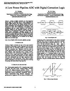
Figure 2. One bit/ stage architecture Figure 2 shows block diagram of an ideal N-stage, 1-bit per stage pipelined A/D converter. Each stage contributes a single bit to digital output. The most significant bits are resolved by first stage in the pipeline. The result of stage is passed on the next stage where the cycle is repeated. A pipeline stage is implemented by the conventional switched capacitor (SC), it is shown at figure 3[1].
Fiure. 3. Scheme of switched capacitor pipelined A/D converter Vrefp is the positive reference voltage and Vrefn is a negative reference voltage. Each stage consists of capacitor C1, C2, an operational amplifier and a comparator. Value of
C1 and C2 are equal in my design. Each stage operates in a sampling phase, a multiplying phase and hold phase. During the sampling phase Φ , the comparator produces a digital output Di. Di is 1 if Vin > Vth and Di is 0 if Vin < Vth, where Vth is the threshold voltage defined midway between Vrefp and Vrefn. During multiplying phase Φ2, C2 is connected to the output of the operational amplifier and C1 is connected to either the reference voltage Vrefp or Vrefn, depending on the bit value Di. If Di = 1, C1 is connected to Vrefp, resulting in the resedu ( Vout ) is : Vout(i) = 2 x Vin(i) – Di.Vrefp (1) Otherwise, C1 is connected to Vrefn, giving an output voltage Vout(i ) = 2 x Vin(i) - Ď.Vrefn (2) And hold phase Φ3, at same multipliying phase with hold value residu voltage for next stage. 3. Precision Comparator With Latch. Precision comparator is implemented to each stage of the ADC. We prefer to use precision comparator then digital correction to minimize offset error of comparator and better output of ADC. This comparator consists of three blocks: preamplifier, decision circuit and output buffer. First block is the input preamplifier which the circuit is a differential amplifier with active loads. The size of transistors M1 and M2 are set by considering the diff-amp transconductance and the input capacitance. Second block is a positive feedback or decision circuit, it is the heart of the comparator. The circuit uses positive feedback from the cross gate connection of M8 and M9 to increase the gain of the decision element. Third stage is output buffer; it is to convert the output of the decision circuit into a logic signal. The inverter (M18 and M19) is added to isolate any load capacitance from the self biasing differential amplifier. The complete circuit of comparator is shown in figure 4.
(a) Presicion comparator
(b) Latch Figure 4. The Precision comparator with latch circuit 4. Operational Amplifier In this pipeline ADCs, operational amplifier is very important to get accurately result. We used an operational
transconductance amplifier which has a gain of approximately 62,6dB for a bias current of 20 µA with Vdd = 3,3 V and Vss = -3,3 V. A value of loading capacitor is 0.275 Pf. The complete circuit is shown in figure 5. Transistors M9 and M10 functions as a constant current source, and transistors M8, M5 and M7 functions as two current mirror 'pairs'. The transistors M1,M2,M3,M4 are the differential amplifier. Transistor M6 is an output amplifier stage. In the simulation, we got the resultat for phase margin (PM) was 140 degre, A gain was 62,2dB and Gain bandwidth product was 800 MHz as fig.6. A power dissipation mesured of
1,6mW.
Figure 5 : Operational Tranconductance Amplifier
Figure 6: Opamp simulation 5. Non-Overlapping Clock In the design pipeline A/D converter use nonoverlapping clock is used to proces sampling , multiplying and hold. Each periode phase at 4,16ns, with used gate not and nand for delay frequency input 80MHz or 12,5ns. So clock used for delay latch circuit output comparator, the purpose keep output parallel. Complete circuit nonoverlapping clock at figure 7. .
Figure 7. Non-Overlapping Clock Circuit 6. Result One stage A/D converter layout was estimated to occupy about 200 µm x 98 µm, it is seen at figure 8. Figure 10. Result Complate 8-bit ADC Pipeline.
Figure 8. Lay-Out ADC Pipeline 1-bit/stage. Figure 9 shows the dc linearity of the ADC at conversion rate of 80 Msamples/s. In the figure 8(a), the code is plotted versus integral nonlinearity (INL) value and figure 8(b), the code is plotted versus differential nonlinearity (DNL). Note that since each simulation lasted 120 minutes, only 250 codes were tested. As shown, the worst INL is less than 0.6 LSB; the DNL is less then 0.6 LSB.
Figure 10 shows the digital 8-bit ADC with vin voltage comparator = 1V and frequency clock at 80 MHz, as same voltage input 2 volt.
result simulation output = 0V for 2V, threshold reference voltage 2V. the periode simulation 3,2us
7. Conclusion The pipeline ADC 8-bits, 80 Msamples/s were implemented in 0.35µm technology CMOS Proces with total power dissipation 130 mW. Refer to result of experiment; the ADC can be implemented for high speed camera. The system use topology one bit per stage with three phase clock with purpose good residu voltage and digital output. 5. References [1] Eri Prasetyo, Dominique Ginhac and M. Paindavoine ,”principles of CMOS sensors dedicated to face tracking and recognition”, In IEEE CAMP05 International Workshop on Computer Architecture for Machine Perception, July 2005. [2] Chong K.Yun, “ 20-stage pipelined ADC with RadixBased Calibration” IEEE J Solid state Circuit, june 2003. [3] A.N Karanicolas , H.S Lee and K.L Bacrania “ A 15-bit 1 – Msample/s digitally sel-calibrated pipeline.”IEEE J
(a) DNL 0,6LSB
Solid-state Circuit, Vol 28 PP, 12071215,dec1993. [4] Paul C. Yu “ A 2,5V 12-bit 5MSPS CMOS ADC “IEEE J Solid-state Circuit, November ,2000 [5] Jérôme Dubois, Dominique Ginhac, Michel Paindavoine, and Barthélémy Heyrman, "A 10 000 fps CMOS Sensor
(b) INL 0,6 LSB Figure 9. Curve of code DNL and INL
with Massively Parallel Image Processing", IEEE Journal of Solid-State Circuits, 43(3) :706-717, March 2008.
[6] Jérôme Dubois, Dominique Ginhac, Michel Paindavoine, "VLSI Design of a High-Speed CMOS Image Sensor with in-situ 2D Programmable Processing", EUSIPCO 2006, September 8, 2006, Florence, ITALY. [7] M. Paindavoine,”High-speed camera with embedded real time
image
processing”,
in
seminar
information
technology of Gunadarma University, june 2006. [8] M. Dessouky and A. Kaiser, “Very low-voltage fully differential
amplifier
for
switched-capacitor
applications," IEEE ISCAS, pp. 441-444, May 2000. [9] Jacob Baker and D. E. Boyce,” CMOS Circuit Design, Layout and Simulation.” IEEE Press on Microelectronic Systems, 1998. [10] G. Palmisano, G. Palumbo and S Pennisi “ Design Procedure for Two-Stage CMOS Transconductance Operational amplifier “ Proceeding, Universita „ di catania 2001. [11] Hao-Yu, xun-Gong, and Juo-Jung hung,” A low power 10 bits 80 Msamples pipeline ADC”, Technical report, ECCS department University of Michigan tech., 2003. [12] Lisha Li,”High Gain Low Power Operational Amplifier Design and Compesation Techniques,” A dissertation, Brigham Young University, April 2007.