The OMEGA architecture provides end-to-end quality of service (QoS) ... cation
with periodic media streams, speci cally a master/slave telerobotics application.
Design, Implementation and Experiences of the OMEGA End-Point Architecture Klara Nahrstedt Computer Science Department University of Illinois at Urbana-Champaign, IL 61801 Jonathan M. Smith� Distributed Systems Laboratory University of Pennsylvania, Philadelphia, PA 19104
Abstract
The OMEGA architecture provides end-to-end quality of service (QoS) guarantees for distributed applications. QoS parameters are translated between application and network requirements by the QoS Broker, thus integrating media and network QoS management into a single entity. Admission control uses a schedulability test derived from application requirements. A novel task priority and precedence based scheme is used to represent complex application requirements and ensure correct feasible schedules. A prototype of OMEGA has been implemented using workstations connected by a 155 Mbps dedicated ATM LAN. To simplify implementation, we assumed a networked multimedia application with periodic media streams, speci cally a master/slave telerobotics application. This application employs media with highly diverse QoS requirements (e.g., interarrival times, loss rate, bandwidth) and therefore provides a good platform for testing how closely one can achieve QoS guarantees with workstation hosts and cell-switching. Experience with this implementation has helped to identify new challenges to extending these techniques to a larger domain of applications and systems, and suggests promising new research questions.
1 Introduction The need for end-to-end QoS guarantees in networked multimedia systems (NMS) has become clear in a number of application domains and while there is a great deal of excitement, a number of research challenges have emerged. At their center, these challenges raise the issue of resource management. There are a variety of views on how this resource management is to be accomplished. One view is embedded in today's IP Internet and UNIX operating system, which might be characterized as communitarian. This means that the system is designed to accommodate additional load by decreasing the \share" of resources given to each system user. This policy, while philosophically attractive, can have some unfortunate consequences for some applications in the face of Research support of both researchers for work at Penn came from Bellcore (through Project DAWN), IBM, Hewlett-Packard, and from the Corporation for National Research Initiatives (CNRI), which is funded by the National Science Foundation and the Defense Advanced Research Projects Agency under cooperative agreement # NCR8919038, and from the National Science Foundation under CDA-92-14924. Nahrstedt's work was supported in part by funds from the Research Board of the University of Illinois at Urbana Champaign �
1
system dynamics, e.g., resource starvation, or at least large variations in delay for less extreme cases (best e�ort QoS). A contrary view, also somewhat extreme, is that resources should be completely dedicated. Such systems are exempli ed by dedicated microcontrollers connected by dedicated communications channels (deterministic guaranteed QoS). The attraction of the rst view is that sharing of resources is maximized, while the attraction of the second is that application requirements are guaranteed to be met, unfortunately at a possibly large cost in e�cient usage of resources. It is our view that while networked multimedia systems may have stringent resource management requirements, these can be accommodated much more e�ciently than with dedicated processors and communications links. New tools for accomplishing this include the link multiplexing technology known as the Asynchronous Transfer Mode (ATM). ATM multiplexing provides greater control of network resource sharing. New algorithms and software technologies, e.g., the TENET protocols and real-time support in operating systems such as IBM's Advanced Interactive Executive (AIX), a version of UNIX, are also helpful. This view can only be realized where there are some limitations on resource sharing. The OMEGA end-point architecture described in this paper has been the result of an interdisciplinary research e�ort which examines the relationships among the requirements of applications, which have periodic resource demands, and the ability of the local resource manager (the operating system) and the global resource management (combining the communications system and remotely managed resources) to satisfy these demands. Focusing on such relationships has provided the necessary insight to identify which issues are meaningful to the end-to-end provision of Quality-of-Service (QoS) to applications, particularly those requiring stringent resource management. The OMEGA architecture presumes a network subsystem capable of providing QoS speci ed via some parameters such as bounds on round-trip or interarrival delays, errors, or throughput. An example of such a subsystem would be a realization of an ATM B-ISDN network [TS93] with METS (Multimedia Enhanced Transport Service) support [CCH93], Native-mode ATM stack [KS95], the TENET suite [FV90, BM91] (RCAP, RTIP,CMTP, RMTP), or other architectures. Figure 1 shows several end-point network/transport architectures for provision of transport-to-transport layer guarantees. OMEGA also presumes an operating system providing some real-time capabilities. To provide application-to-application guarantees, these components in isolation are not enough. The contribution of the OMEGA architecture is: � Integration of application, OS and network resources in Networked Multimedia Systems (NMS) for end-to-end QoS guarantees; � Integration of application QoS with network QoS towards end-to-end QoS; � Use of a global precedence graph shared by the application, I/O and transport subsystem for time synchronization among all task participating in successful end-to-end QoS of a networked multimedia application. � Transfer of task priorities from the application to the transport subsystem. The rest of the paper is organized as follows: in Section 2 we describe communication and resource models used for the OMEGA architecture. Section 3 brie y discusses the design of the QoS Broker[NS95], and concentrates on services for provision of QoS during the call establishment phase. In Section 4 we describe our experimental testbed, implementation, and measured results. Section 5 concludes the paper with lessons learned and suggests promising directions for future research. 2
Application Subsystem
Transport Layer
XTP
RTIP
HeiTS ST-II
IP
QoS-A
CMTP/ RMTP
Network Layer Data Link Layer
Native-mode ATM Stack
OMEGA
RCAP RSVP
Physical Layer
Transmission Protocols
Establishment Protocols
Figure 1: End-Point Architectures Providing Guarantees according to QoS Readers interested in real-time systems and scheduler design should pay particular attention to Sections 3.2.2, 3.3, 3.5, 4.2.4 and 4.2.5. Readers interested in networking can skim these sections, but should capture from Section 3.5 that the protocol elements must be part of the scheduling discipline. Roboticists can obtain important highlights of the work from Sections 3.2.1, 4 and 5.
2 Modeling of OMEGA Architecture We model networked multimedia systems (NMS) as end-points connected by a network infrastructure. Network infrastructures such as ATM can provide customized connections where the properties of tra�c within the network are guaranteed within some limits. Applications, however, rarely interact directly with the network, but rather, interact via an intervening operating system. The operating system implements a sharing policy under which processing capacity is shared between applications. The set of applications, the operating system, and the protocol stack comprise the end-points of the NMS. The OMEGA architecture is an end-point architecture for provision of QoS guarantees in NMS. We assume in this paper that network management and transmission protocols for provision of guarantees in intermediate network nodes exist [PZF94, CCH93, KS95] and concentrate on the role and elements of OMEGA. Hence, together with a proper network management for QoS guarantees OMEGA achieves global application-to-application guarantees. Since OMEGA functions can be partitioned into remote and local, we model the system in two parts, (1) the communication model, and (2) the resource model at the end-points.
2.1 Communication Model
The communication system is modeled as a two layer system (Figure 2).
2.1.1 Application Subsystem
The application subsystem layer contains the functions of the application and session layers which comprise the Real-Time Application Protocol (RTAP). Application protocol functions specify the 3
Application Protocol
(RTAP)
Real-Time
Call Management
Connection
QoS Broker
Application Subsystem Transport Subsystem
Real-Time
Network Protocol (RTNP)
Management
Figure 2: OMEGA Communication Model goal of the application. Our example is a set of application protocol functions for support of realtime remote control applications. For other applications, the set of functions might be di�erent. The basic set of functions is : call management for uni-directional media streams, read/write of Application Protocol Data Unit (APDU) such as display images, grab data from a device, input/output device rate control for multimedia devices, and error detection/reporting. Optional functions are manipulations of an APDU such as fragmentation, integration/disintegration (which depends on the size of an APDU and the similarity/dissimilarity of application QoS), and intraframe synchronization if application subsamples are speci ed.
2.1.2 Transport Subsystem
The transport subsystem layer includes the functionalities of the network and transport layers using Integrated Layer Processing [CT90]. Network protocol functions provide services between the application subsystem and the network host interface. They build the core of the Real-Time Network Protocol (RTNP). The basic services are: connection management for uni-directional connections, data movement from/to application ring bu�ers to/from network host interface, and time error detection/reporting mechanism. As an optional function, we currently support a Forward Error Correction mechanism.
2.1.3 QoS Broker
Both subsystems must provide guaranteed services over speci ed calls/connections for applications. Therefore, they require guarantees on the resources needed for the communication. Resource guarantees are negotiated during the call establishment phase by the QoS Broker protocol [NS95] which is an addition to the communication architecture present in both application and transport layers, as shown in Figure 2. The broker orchestrates both local and global end-point resource availability.
2.2 Resource Model
At the end-point, three logical groups of resources (Figure 3) must be managed, namely multimedia devices, CPU scheduling and memory allocation, and network resources. As can be seen from the
diagram, this grouping follows the communications layering model for the application and transport 4
Sending/Receiving Connections
Buffers
Memory
Network
Tasks
Application QoS Parameters
CPU Scheduling
Input/Output Devices
System QoS Parameters
Application Subsystem Transport Subsystem
Multimedia Devices
Network QoS Parameters
Figure 3: OMEGA Resource Model subsystem, but since the operating system functions are shared by both layers, the layer boundary should not exist. We describe all end-point resources with Quality of Service (QoS) parameters maintained in small pro les, which represent the requirements for the resources [NS95]. The resources in each domain (application, OS, network) maintain domain-speci c representations. Therefore, we introduce multiple views of QoS:
� Application QoS Parameters
Application requirements for multimedia devices are speci ed with application QoS parameters. For example, video quality is described with frame rate (30 frames/s), frame size (height * width in pixels), color ( bits/pixel), etc. The application QoS of a multimedia stream consists of descriptions of both the qualities of individual media within the stream, and the way in which these media are combined in a multimedia stream. We call these descriptions media qualities and media relations. The media quality component consists of an interframe speci cation and an intraframe speci cation. The interframe speci cation gives the characteristics of a homogeneous media stream (e.g., sample size, sample rate, loss tolerance). If the individual samples in the stream di�er in quality, intraframe speci cation must occur. The media relations specify relations among the streams. Synchronization skew represents a time o�set between two streams in a single direction. Precedence relation speci es any time dependency between two streams in di�erent directions. For example, in the telerobotics application (see discussion in 3.3.2), there exists a precedence relation between the sensory stream carrying position information from an operator to a robot, and the sensory stream carrying feedback information from a robot to an operator. Communication relation de nes the communication topology such as unicast, multicast, or broadcast. Conversion relation speci es transformations of a medium (e.g. conversion from audio to text in speech recognition application). The parameters are stored in an application QoS pro le. An example of an entry in the application QoS pro les (in pseudocode) is: MEDIA_QUALITY: Type = ROBOT; Intra_spec = FALSE; /* no interframe specification */
5
Direction = INPUT; Sample_size = 64; Sample_rate = 50; /* 50 samples/sec */ End_to_end_delay = 20; /* upper bound 20 ms */ Loss_rate = 1 /* 1 sample/sec */ Importance = HIGH_IMPORTANCE;
� Network QoS Parameters
The transport subsystem is con gured with network QoS parameters, which describe the requirements on the quality of the network connection (network resources). The network QoS contains the throughput speci cation (e.g., packet size, bandwidth, burstiness), tra�c speci cation (e.g., packet loss, jitter, end-to-end delay) and performance speci cation (e.g., ordering, error correction, fragmentation). The network QoS parameter structure describes the QoS of data over a single network connection. The parameters are stored in a network database at the end-point. The network pro le includes as many network QoS descriptions as there are active connections for sending and receiving data.
� System QoS Parameters
The OS behavior is speci ed by system parameters which are stored in a system pro le. The system parameters mirror the requirements on CPU scheduling (e.g., task start time, duration, and deadline) and bu�er allocation of the multimedia stream across both subsystems. Perceptual QoS is outside of the OMEGA architecture; it represents the sense-perceptive quality view of a human user (e.g., TV quality of video, telephone quality of audio). It is hard to quantify and its evaluation is subjective and user-dependent. As we explained in the introduction, resource allocation must be performed for guarantees to be made. We also noted that one of the key questions was the strictness with which resource allocation would be performed versus the potentially contrary design goal of accommodating dynamics. The point at which the allocation decisions are made in a networked system (such as those we focus on) is called \call establishment". The next section of the paper explains the new mechanisms and techniques we have developed for the end-to-end call establishment in the OMEGA architecture.
3 Call Establishment Among the new mechanisms for the end-to-end call establishment are the QoS Broker, and its underlying services for a proper preparation of the schedulable protocol stack. A full description of the QoS Broker protocol design and implementation is presented in [NS95]; we provide a brief overview here and concentrate on a detailed discussion of services used by the broker, which are illustrated in [NS95] only through examples.
3.1 Design of QoS Broker
Previously, QoS requirements were speci ed in terms of network QoS parameters and the application speci ed these parameters to the network. The answer was either Yes, the requirements can be met, or No, the network cannot provide resources for the required quality (Figure 4). However, 6
QoS Request/Response
QoS Brokerage
driven by Application
System User
Application
QoS/Y/N
QoS
QoS Broker Y/N
QoS QoS/Y/N QoS/Y/N
QoS/Y/N
Application
CPU/OS
System (Network)
Network
Figure 4: The QoS Broker Concept to provide applications with end-to-end guarantees, network resource management alone is not su�cient, particularly when end-points become more sophisticated (e.g., workstations are equipped with a rich set of multimedia devices, and support multiprocessing and multiple users.). This requires balancing resources among the application, network, and operating system within the endpoints as well as balancing resources between end-points and the network [And93]. As a part of the OMEGA system, we designed and implemented a resource management entity, called the QoS Broker, which provides local and global resource management as shown in Figure 5. Local Availability of Resources
Global Availability of Resources
Application Subsystem
QoS Broker
QoS Broker
Resources
(BUYER)
(SELLER)
Local Operating System
Remote
Resources
QoS Translation
Resources
Admission
Resources
Negotiation Renegotiation Transport Subsystem Resources
Network Resources
Figure 5: QoS Broker Functionality Local resource management services include communication of QoS parameters among appli-
cation, network and operating system components, testing for availability of end-point resources based on QoS requirements, and reservation/allocation of these resources. This is achieved by using subservices such as translation among di�erent QoS views (such as those illustrated in Figure 3) and admission. For global resource availability, the broker uses a negotiation protocol between the end-points and relies on network resource guarantees provided by the network subsystem, e.g., by B-ISDN switches. The goal of the broker is to negotiate a resource deal among all the system components (application, OS, network). In the negotiation process, the broker assumes di�erent roles (seller and buyer) to distinguish between the participating partners. 7
Negotiation is performed during the establishment phase. During the transmission phase of the communication system, QoS parameters can change due to (1) network resource change (e.g., congestion occurred because some other source-user did not behave according to the deal), (2) OS resource change (e.g., priority inversion), and (3) user/application requests for change (e.g., the goal of task changed). To accommodate a QoS parameter change, we support a renegotiation service. In the next subsections, we discuss individual services participating in the QoS brokerage process.
3.2 Translation
To enforce coordinated management of the resources at the end-points, multiple QoS views must be translated among each other. This is done by translation services. These services, in brief, translate QoS speci cations between layers in the system.
3.2.1 Tuning Service
The tuning service provides a translation between the perceptual QoS and application QoS parameters. The goal of this service is to allow the human user to specify QoS using his/her senses, rather than numbers and text. We provide a graphical user interface (GUI) and use sample audio/video clips. For a telerobotics application, the sample might be an animation/video clip of a robot arm to specify the required video frame rate. An example is shown in Figure 6.
15
Range
Range
520x480
240x160
1 Frame Size
Frames/second
Figure 6: Graphical User Interface The user controls the perceptual quality of the video display by adjusting the application (playback) QoS parameters, such as frame rate and picture size, by manipulating a set of sliders. The positions of the sliders encode values for application QoS parameters. The GUI allows the user to immediately see the correlation between the perceptual and application quality parameters. The prototype is a rst step towards user-directed QoS parameterization. General translation between perceptual QoS and application QoS is nontrivial and still an open research issue, largely because the perceptual issues are not completely understood. Future research will likely focus on the interplay between computer-human interface research, and the support mechanisms for multimedia display and interaction. 8
3.2.2 QoS Translator
The translation between the application QoS and the network QoS is performed by the QoS Translator service. The translation is bidirectional and may includes at least three activities: 1. One-to-one translation (1-1 mapping) involves a translation between the medium quality and network connection quality. In our prototype, we focused on translation relations between periodic uncompressed streams and CBR (Constant Bit Rate) tra�c, however, this is only a subset of translation relations. Table 1 gives the notation for our variables used in 1-1 mapping; we use x0 to denote a changed variable x. Table 2 gives a set of translation relations between media quality (application QoS)
MA RA
Application Subsystem (A)
Transport Subsystem (N)
MN Packet Size RN Packet Rate ITN Interarrival Time between Packets PA Period between Samples PN Period between Packets CA End-to-End Delay CN End-to-End Delay LRA Sample Loss Rate LRN Packet Loss Rate IA Sample Importance IN Packet Priority BN Bandwidth S TA Guaranteed Application Service HHD Host-to-Host Delay Time per Sample at the Sender TAR Guaranteed Application Ser- BN Bandwidth vice Time per Sample at the Receiver Table 1: Basic Notation for Application and Network QoS (Quantitative Parameters) Sample Size Sample Rate
and throughput/tra�c speci cation (network QoS). The translations involving change may cause ambiguity when performing inverse translation from network QoS to application QoS. For example, the BN 0 change (Table 2) can result either in change of the APDU size MA 0 or the application sample rate RA 0. The media relations a�ect the performance speci cation as follows: � Packet Priority (IN ) is inherited from the sample importance (IA). � The speci cation of communication (unicast/multicast/broadcast) is copied to the communication type. � Fragmentation is set TRUE if dMA =MN e > 1. If fragmentation occurs, it in uences the performance for CA because new operations must occur which requires additional processing time. � Ordering is set TRUE, if continuous media with real-time behavior are sent. For nonreal-time media, the ordering requirement merely depends on the application's ability to handle out of order data. 9
Relation
A�ects
dMA =MN e > 1
A TA ) CN = (CdAMAT=M Ne
Fragmentation and CA RN , Tra�c Shaping ITN ITN , Tra�c Shaping ITN , Tra�c Shaping CN
LRN = LRA
LRN
LRN = LRA � dMA=MN e
LRN
BN = RN0 � MN R0N = MBNN MA0 = bR0N =RAc � MN R0A = R0N =dMA =MN e CA0 = d MMNA e � CN0 + TAS + TAR
BN RN MA0 R0A CA0
RN = dMA =MN e � RA ITN = PA = R1A ITN 2 (0; PN ) ITN 2 (PN ; PA) S
R
A�ected by
Additional Notes
PA PN = R1N , dMA =MN e > 1 PN ; PA
no fragmentation, dMA =MN e = 1 ITN for 2 consecutive packets from same sample ITN for 2 consecutive packets from 2 di�erent samples
Size of MA and MN MA ; R A
CA; TAS ; TAR; dMA =MN e LRA LRA , dMA =MN e RN ; MN BN0 BN0 BN0 dMA =MN e, CN0
Network loss rate for reliable medium Network loss rate for loss-tolerant medium After computation of RN After negotiation response; RA is xed MA is xed if (CA0 > CA ) ^ (dMA =MN e > 1) ) (MN0 > MN )
Table 2: 1-1 Mapping between Media Quality and Throughput/Tra�c Speci cation
� Error Correction depends on the importance parameter (IA) and sample loss rate (LRA)
of the medium quality. If real-time behavior of the continuous media is required, its importance is high and sample loss rate is low, then a Forward Error Correction (FEC) [Bie93] mechanism is used in the RTNP protocol. In other protocol suites, a di�erent error correction mechanism (e.g., selective retransmission) can be speci ed. In our RTNP implementation, if FEC is not needed, then only error detection is performed. � Cost and Burstiness mappings are currently not supported.
2. Mixing means multiplexing (at the application subsystem level) di�erent media into a single stream which will be sent through a single network connection, as shown in Figure 7. After mixing, a one-to-one translation occurs between the resulting mixed media quality and the network QoS for a connection. The resulting medium quality is the union with precedence of the media qualities being integrated. Mixing should be done on media which have similar QoS requirements, otherwise a stream with unrealistic QoS requirements will result. Because the translation is bidirectional, ambiguities can also occur in this case. Therefore, the QoS Translator passes to the application several possibilities and lets the application/user 10
Media 1 Quality Parameters Sample Size (M 1) Sample Rate (R 1) End-to-End Delay (C 1)
Media Quality Parameters
Sample Loss Rate (LR 1)
Media 2 Quality Parameters
Sample Size (M)
M =
Sample Rate (R)
R = max(R 1, R 2)
End-to-End Delay (C)
C = min(C 1,C 2)
Sample Loss Rate (LR)
LR =
Sample Size (M 2) Sample Rate (R 2)
End-to-End Delay (C 2) Sample Loss Rate (LR 2)
Figure 7: Media Quality Mixing decide which medium will su�er in quality. In a more sophisticated system, a rule-based QoS Translator can be deployed which will make decisions based on rules given by the user a priori. 3. Splitting means demultiplexing (at the application subsystem level) a media stream into several streams which will be transmitted through several connections. This occurs when the medium stream carries di�erent kinds of information (e.g., in a MPEG compressed video stream we have speci cation of I-frames, P-frames, and B-frames). Since the interframe medium quality speci cation includes the intraframe speci cation, the QoS Translator can perform one-to-one translation immediately between the intraframe component speci cation and the network QoS.
3.2.3 Layer-to-OS Resources Translation
Each communication layer uses OS resources; hence, a mapping between the layer QoS parameters and OS requirements is needed. We consider translations between application QoS parameters and OS resources with respect to the application subsystem protocol (RTAP), as well as network QoS parameters and OS resources with respect to the transport subsystem protocol (RTNP). This mapping is done within the admission services.
3.3 Admission
Admission control is an essential element to achieve guaranteed services. For distributed multimedia communications systems, each resource along the path(s) between source(s) and sink(s) must monitor its availability [And93]. In our OMEGA architecture, the control and monitor of end-point resources is done by the QoS Broker, which performs admission control at both layers of the OMEGA system (Figure 2). For the admission and scheduling of RTAP and RTNP protocol data units (PDUs) we assume that (1) RTAP and RTNP protocols consist of set of tasks where each task is processing one PDU; 11
(2) for ease of implementation, we assume networked multimedia applications with periodic media streams; (3) aperiodic requests may occur, for these requests our scheduler polls periodically and treats them as deadline-driven requests; (4) all tasks (application and network) are non-preemptive basic tasks. Non-preemptive algorithms are relatively easy to implement, but the drawback is that a high priority message can be blocked by a long low priority message. This is called priority inversion [R.L94]. Due to the isomorphic mapping between the communication message (application PDU or network PDU) and its equivalent protocol tasks, the application/network QoS parameters are mapped onto the system parameters (1) task priorities, (2) task periods, and (3) bu�er space requirements as follows: The application task priorities are inherited from the importance of the stream sample and equivalent to the assignment of priorities according to task deadlines (Section 3.3.1). For network tasks, the task priorities are inherited from the application tasks as discussed in Section 3.3.2. The importance of priority inheritance for support of guarantees is clear. Task durations are pre-computed and stored a priori in the system QoS pro le. This is an approach used in the real-time system community when using dedicated resources. However, because we are working in a communitarian environment, we are aware of non-deterministic variations due to I/O or CPU load which are not strictly controlled and do not provide QoS guarantees. Simple QoS monitoring and adaptation services are used for dynamic resource allocation adjustments. Our current implementation does QoS monitoring, but when violations of deadlines during the transmission phase occur, a QoS degradation report is issued to the user and the user takes a renegotiation action; this can be viewed as a form of exception handling. There is no automatic dynamic resource allocation adjustment. Task processing times are estimated using a worst-case sample of measured resource utilizations. In practice, such pessimistic estimation let the tasks meet their deadlines. The task period (P ) is computed as the inverse of the sample rate/packet rate. The sample/packet size, fragmentation/reassembly, mixing/splitting, and error correction mechanisms determine space requirements. In our communication protocols, we allocated at least 2 � MA space for each unidirectional channel for ring bu�ers, so that sampling and transport can be overlapped.
3.3.1 Admission Service in the Application Subsystem
The admission service performs four tests at the application subsystem level: device quality test, local schedulability test, end-to-end delay test and bu�er allocation test. These tests check the multimedia devices and system resources availability for the RTAP. Using the naming convention of Tables 3 and 4, the tests are summarized in Table 5 and discussed below: � The device quality test compares the con guration parameters of the multimedia devices with the speci ed application QoS requirements. For example, if a video device can provide a maximal frame rate of 15 frames/second and the user speci es the application QoS sample rate as 30 frames/s, then the admission service either rejects the QoS requirement and waits for correct user input, or \falls back" to the possible QoS and informs the user of the change. � The local schedulability test takes the system QoS parameters which specify the application tasks for processing of multimedia streams and checks if the tasks are schedulable. The behavior of the considered application tasks allows us to test the tasks as if they would be 12
Application Subsystem
i
index of streams
d
k ki direction d
Transport Subsystem
index of connections index of connections carrying i stream index for connection direction S/R
index for stream (S)end/(R)ecv r index of RTAP tasks m index of RTNP tasks ri index of RTAP tasks per stream i mk index of RTNP tasks per connection k rd(i) index of RTAP tasks per stream i in md(k) index of RTNP tasks per k in direction d direction d csA RTAP tasks context switch time csN RTNP tasks context switch time j index of cs among RTAP tasks n index of cs among RTNP tasks eA processing time of a RTAP task eN processing time of a RTNP task i ! i0 relation: stream i precedes stream i0 Table 3: Indices for QoS Parameters in Admission Service scheduled using modi ed non-preemptive Rate-Monotonic scheduling policy1. The modi ed schedulability test translates for the application subsystem to the test #(1) in Table 5. Further, for each stream i in direction d, the deadline test #(2) in Table 5 holds. This means that we at rst admit 1 stream testing (1) and (2), then admit stream 2 under the consideration that resources for the previous stream 1 were already allocated, etc. If the schedulability test #(1) cannot be met, the stream with later deadline (lower rate) will be rejected. If the schedulability test is satis ed, the task precedences are assigned according to their deadline (highest priority is assigned to the earliest deadline). If there are input and output tasks with the same period, the input tasks get higher precedence than the output tasks. � The end-to-end delay (EED) test consists of two steps. At the buyer side, the test #(3) takes the durations of the local buyer application tasks and checks them against the speci ed QoS EED (CA ) bound. Here, we make sure that the tasks, although schedulable, don't violate the EED requirement. This is especially important in cases where PA > CA . For example, sensory data in telerobotics provide such a behavior (e.g., the task period is PA =20 ms and EED CA =10 ms). At the seller side, all processing times of application tasks ri , network tasks mk over connections ki , which carry the stream i, and the actual network latency HHD (Host-to-Host Delay) is taken into account. The test #(3') must hold. � The bu�er allocation test checks if there is enough memory for the ring bu�ers to lock them in real memory and smooth the tra�c jitter. Smoothing tra�c is required when measured EED < requested EED. Real-time networked applications want the right data
P
The general Liu and Layland [LL73] schedulability test is modi ed for non-preemptive tasks: n r 1 minr (P r ) r=1 e � 1 1
13
Pnr
=1
er Pr
�
Variable Name SI
TAi TAS(i) TAR(i) TA1;:::;i
1
TNk TN1;:::;k WFF
1
max. number of schedulable intervals aggregate processing time of all RTAP tasks per stream i (one sample) aggregate processing time of RTAP tasks per sending stream i aggregate processing time of RTAP tasks per receiving stream i allocated time of all RTAP tasks to process previous 1; :::; i 1 streams in period mind(i)(PAd(i) ) time of set of RTNP tasks per connection (packet) k allocated time of all RTNP tasks to process 1; :::; k 1 previous connections in period mind(i) (PAd(i) ) wait for feedback time (i ! i0)
Relation
n
lcm(PA ;:::;PA ) SI = min n) (PA ;:::;PA 1
1
TAi = Pr erAi + Pj csjAi TAS(i) = Pr erAS i
( )
TAR(i) = Pr erAR i
( )
TA1;:::;i 1 = Piii=11 TAii TNk = Pmk emN k + Pn csnNk 1 TNkk TN1;:::;k 1 = Pkkk=1
WFF = 02 � HHD + (Pk TNR(k ) + TAR(i)) + i 0 (Pk TNS (k ) + TAS (i )) i
Table 4: Abbreviated Naming and Relations for Admission Services at the right time (requested EED), not sooner or later (although sooner is still better than later). The ring bu�ers are pinned into real memory, hence Test #(4) holds in our system. The size 2 � MAi is then locked in the memory. The 32 MBytes is an upper bound which can be allocated as a pinned region for user processes in the AIX 3.1 system.
3.3.2 Admission Service in the Transport Subsystem
The admission service at the transport subsystem level performs tests on network resources such as a throughput test, rate control test, network EED test, and system resources such as CPU schedulability test for RTAP/RTNP. Table 6 summarizes the admission tests in the transport subsystem. � The throughput test controls the assignment of bandwidth to individual connections. The upper bound of available aggregate throughput at the end-point is determined by the network host interface and its device driver. For example, in our system the ATM host interface (hardware) provides a transmission rate of 155 Mbps, however, the ATM transport subsystem, after overhead, provides 135 Mbps [ST93]. Hence, any throughput requested for the sending or receiving connections is checked against the 135 Mbps limit bound (Test #(6)). 14
Admitted Resources
Admission Tests
CPU for i (TA1;:::;i 1 + TAi � mini (PAi ) Deadline for i TAi � PAi EED for i at buyer side TAi < CAi EED for i at seller side (TAS (i) + TAR(i) + (Pd Pk TNd(k) + HHD)) � CAi Bu�er for i 2 � MAi < 32MBytes Table 5: Admission Tests in the Application Subsystem for Stream i
Admitted Resources
Bandwidth Rate Control CPU for ki Deadline for ki CPU0 for ki if (TAR(i) TAS(i ))
Test # (1) (2) (3) (3') (4)
Admission Tests P
Test #
TA1;:::;i + TN1;:::;k 1 + WFF + TNk � mini (PAi ) TNk � CNk Pd T d(k) + HHD � C k N N
(10') (11) (11')
BNk � 135Mbps k Pd Pk Rd(k) � 1000 N TA1;:::;i + TN1;:::;k 1 + TNk � mini (PAi ) TNk � PNk 0 i0 i ! TAS(i + TAR(i) + TNS(k ) + TNR(k ) + WFF � PAi0
EED for k at buyer side EED for k at seller side Table 6: Admission Tests in Transport Subsystem
(6) (7) (8) (9) (10)
� The rate control test checks the packet rate RN for each connection k in sending and receiving
directions against a certain bound (in our implementation, 1000). This bound results from the OS cost (due to overhead) of moving data between the user and kernel space (Test #(7)). � The end-to-end delay test checks the duration of network tasks at the end-points against the required end-to-end delay bound. The same approach as in the application subsystem with respect to buyer #(11) and seller sides #(11') must be considered here. � The schedulability test checks the schedulability of all tasks (application and network tasks). The scheduling at the transport subsystem level, where we test schedulability of tasks (application and network tasks) sharing a single processor, must consider the following time dependencies: 1. Time dependencies between application and network tasks We cannot use the modi ed RM scheduling and priority assignment according to rates at the transport subsystem as discussed in Section 3.3.1. The application and network tasks share a single processor and are time dependent on each other, and network tasks may not be strongly periodic, as is the case for application tasks which must be considered in the schedulability tests and priority assignments (see the computation of ITN 15
in Section 3.2.2). The dependency (precedence ! [NS94]) relation is, for example, read sample(i) ! send packet(ki ). A further implicit precedence between application and network tasks is receive packet(ki )) ! write sample(i). The priority is assigned by the application subsystem to the application tasks (according to the rate) and the network tasks must inherit these priorities in order to enforce joint scheduling. The schedulability tests in the transport subsystem for this type of dependency are #(8) and #(9). To illustrate the tests (8) and (9), consider two streams 1 and 2 to be admitted. Figure 8 shows the ow of admission. ADMISSION IN APPLICATION SUBSYSTEM Admit App QoS and RTAP Tasks
Admit App QoS and RTAP Tasks for Stream 2
for Stream 1
Admit Net QoS and RTNP Tasks
Admit Net QoS and RTNP Tasks
of Connection 1
of Connection 2
for Stream 1
for Stream 2
GLOBAL ADMISSION IN TRANSPORT SUBSYSTEM
Figure 8: Global Admission Flow (Example for test # (8)) The network tasks TNk , added to TA1;:::;i in test #(8), might violate the schedulability test, hence, some task might be rescheduled to the next interval(s), if #(9) is valid. In the case of sending tasks, sending network tasks are rescheduled to the next interval(s), if they satisfy the network EED test #(11,11')2. In the case of receiving tasks, the application tasks might be rescheduled (see Figure 11). Again, the EED tests # (11,11') need to be checked.
2. Time dependencies between input/output streams When testing for schedulability of tasks at the end-points, other types of time dependencies might occur and must be considered. For example, Figure 9 shows sensory data dependency relations in our telerobotics application, where the operator sends position data - sample l in stream i, the slave receives the data and returns the force feedback data f (il). The application needs f (il) so that the computation of the next sample in stream il+1 can be based on f (il). If this kind of dependency occurs, a wait for feedback (WFF) time interval must be included into the schedulability test because the input and output stream information are interdependent. The schedulability tests for these types of dependencies at an end-point (e.g., the operator side in the telerobotics) are #(10,10'). The knowledge of WFF time can be utilized for scheduling of another task which serves a di�erent stream. At the slave side the schedulability test #(8) can be used. 2
The number of possible intervals to schedule a task is SI (Table 4).
16
Operator
App.
i
0 i
Host-Host Delay
l
Progressing Time
Net. f(i App. 20
l
f(i
Slave
l
Net. i l
Wait for Feedback
Net.
Network
l
App.
i
App.
f(i
Net. f(i
l l
l
)
)
Host-Host Delay
) )
Figure 9: Distributed Scheduling - Precedence Graph (Example) The QoS Broker gets the application precedence relations from the user (through application QoS parameters) and together with the implicit application/network precedence relations it creates a precedence graph (see Section 3.5.3). According to the precedence graph, negotiation and admission services provide the distribution and acceptance of the system QoS parameters (tasks). The broker suggests a joint schedule based on time slicing [NS94]. The joint schedule consists of an ordered set of RTAP/RTNP tasks where each task includes an assignment of a feasible time slice. Given a precedence relation among tasks, a feasible time slicing is de ned as one which assigns to each task a interval preserving precedence ordering. � The bu�er allocation test is needed if the network tasks queue the incoming/outgoing packets. Our current system queues packets (ATM cells) in the network host interface (ATM layer) and application PDUs at the application subsystem level, but not in the transport subsystem.
3.4 Negotiation/Renegotiation
The QoS parameters are exchanged between brokers (buyer and seller) through peer-to-peer negotiation as well as between layers using layer-to-layer negotiation.
� Peer-to-peer Negotiation
The peer-to-peer negotiation is separated into two levels: application QoS negotiation and network QoS negotiation. This approach allows the application to negotiate application speci c goals without reserving/allocating/holding shared network resources (which might be expensive). The network negotiation of QoS exchanges negotiation messages about the tra�c quality on di�erent connections. The sender reports connection/network QoS values mappings. The remote side checks its own capabilities to provide the receiving tra�c quality and reports the result to the sending subsystem. The network QoS parameters can be also changed by the network management. Hence, this negotiation is actually a three party negotiation because the network management at the switches can modify the QoS. The response is either `accept', `modify' or `reject'. For `accept'/`modify', the response is sent to the broker buyer with the 17
possible network QoS, which means that resources are allocated. In case of `reject' deeper analysis must occur as to what media, which connections, and what quality were rejected. For example, if robotics data and their quality is rejected, the multimedia call makes no sense, so the application has to terminate. A possible application negotiation in our implementation is described in Section 4.2.3.
� Layer-to-layer Negotiation
If the negotiation at the application subsystem level succeeded, the QoS Broker initiates application-to-transport negotiation. From the view of the application it is a negotiation because application QoS parameters are forwarded (through the QoS Translator) to the transport subsystem, and the transport subsystem negotiates the QoS values within the subsystem and may change them. The translated application QoS values come to the buyer (initiator) application subsystem. An important part of the negotiation process is the bidirectional translation of QoS parameters done by the QoS Translator as described in 3.2.2.
The ow of negotiation is shown in Figure 10. Buyer
Seller
Admit Negotiate App QoS Send App QoS
Peer-to-Peer Negotiation
Recv App QoS Admit Send Response Recv Response ‘accept’
Translate App QoS to Net QoS Layer-to-Layer Negotiation
Admit Negotiate Net QoS Send Net QoS
Peer-to-Peer Negotiation
Recv Net QoS Admit Send Response Recv Response
Figure 10: Flow of Negotiation Renegotiation is performed during the transmission phase. The joint schedule includes a task `renegotiation' which is scheduled periodically to read a shared variable. The user/application or network can store their request for renegotiation and one possible parameter to change3 . If a request for change is speci ed, the QoS Broker is invoked (now in renegotiation state) and it changes the contract. Currently, in our implementation we allow the change of only one parameter - video frame rate. Further, we allow only the relaxation of the bound because we want to do renegotiation in real-time. If a tighter bound is speci ed than negotiated, the renegotiation can't be made in real-time because a new schedulability analysis must be performed. In this case, the QoS parameters must be negotiated from the beginning, i.e., the medium call/connection has to be torn down and a new connection must be established. 3
18
3.5 Schedulable Protocol Stack
The RTAP/RTNP protocol functions (tasks) are scheduled according to the joint schedule which the broker creates using QoS requirements. The broker puts this schedule in the system QoS pro le. The joint schedule represents the contract of the broker and it is a precedence graph of protocol functions with respect to explicit precedence relations (speci ed in application QoS) between protocol functions within a protocol layer and implicit precedence relations (given by the protocol stack structure) between the protocol layers to provide global guarantees. The implementation is detailed in [Nah95]. We will show on an example (Figure 11) how the algorithm for computation of the precedence graph works. sensory data send
feedback sensory data receive
1
3
2
R(f-sen) T A
S(sen) T A
Register streams
video receive R(v) T A
S(sen l+1) T A
R(f-sen l ) T A Application Precedence
S(sen) T A
Graph Globale
R(f-sen) T A
S(sen) T A
Precedence
R(v) T A
R(v) T A
R(f-sen) T A
Graph 1 T N
3(v ) T 1 N
2 T N
3(v ) 2 T N
WFF Time Slicing T 1 N
T S(sen) A
WFF
T S(sen) T 1 WFF T 2 T R(f-sen) T3(v 1) N A N A N
s
1
T 2 N
T R(f-sen) A
T3(v 1) N
T S(sen) T 1 WFF T 2 T R(f-sen) T3(v 2 ) A N N N A
s
T3(v 2) N
T S(sen) T 1 WFF T 2 T R(f-sen) TR(v) A N A N A
s
2
T R(v) A
3
Figure 11: Precedence Graph Creation and Mapping to Time Slicing We consider at the buyer side registration of (1) one sensory stream sen in direction (s)end (application task period - 20 time units; one-to-one translation), (2) one sensory stream f-sen in direction (R)ecv (application task period - 20 time units; one-to-one translation) and (3) one video stream v in direction (R)ecv (application task period - 60 time units; one-to-one translation). The lcm is 60 time units, and the number of intervals, scheduled di�erently, is SI = 3 (see Table 4 for computation of SI ). The intervals are labeled as s1 ; s2; s3. The tasks are labeled according to Tables 3 and 4. The algorithm for computation of precedence graphs works as follows: First, the user registers (speci es application QoS) sending sensory stream with equivalent application task TAS (sen) , receiving sensory stream with TAR(f sen) , and receiving video stream with TAR(v) . Second, we check if resources for application subsystem tasks are available. It means, in the application subsystem admission phase TAS (sen) ; TAR(f sen)andTAR(v) are checked for schedulability, EED and bu�er requirements (tests in Table 5). When these tests are satis ed for the application 19
tasks, the broker forms the tasks into a application precedence graph. Third, in the transport subsystem, the resources for application and network tasks are checked together for availability as follows: The broker-buyer at the application layer gets the corresponding task TAS (sen) , checks the schedulability and end-to-end delay and if they are satis ed, it appends it to the scheduler list in interval s1 (as \reserved"). Going through the brokerage process at the transport level, the broker gets the corresponding network task TN1 , does tests on both tasks TAS (sen) and TN1 (tests #(8,9)). If the tests are satis ed, it appends the network task to the task queue in s1 . After getting accept from the broker-seller, the broker-buyer changes the state for the scheduling task to \allocate". In the next step, the broker-buyer takes the receiving sensory stream, and computes gcm from period of both sensory streams (the already accepted S (sen) and the one to be admitted R(f sen)). Next, the broker obtains the corresponding application task TAR(f sen) and according to the precedence relation it orders the task in the task queue with respect to the previous application tasks. At the transport level, the network task TN2 including the application precedence relation (force feedback data should be received before the next position is sent out) are tested together with the corresponding application task TAR(f sen) and all previously accepted tasks (tests #(10,10')). If the tests are positive, the tasks are appended according to their precedence relations to the global scheduler. The ordering of the tasks is (TAS (sen) ; TN1 ; WFF; TN2 ; TAR(f sen)). In the next step, the corresponding application task TAR(v) for video is taken and checked against tests in Table 6. If tests are positive, TAR(v) is appended to the interval s1 . In the following step, we consider the network tasks TN3(v ), TN3(v ) which transport video fragments. They preempt TAR(v) from s1 to s3 because of the implicit precedence relation between transport and application tasks in receiving direction and violation of test #(8). All equivalent video application/transport tasks are appended to the global precedence graphs accordingly. Note that when video stream starts to be included the number of intervals increases to 3. Hence, copying of previous tasks must be done before appending corresponding video tasks. The reason is that the copied tasks are already accepted. 1
2
4 Validation of OMEGA Architecture We validated the OMEGA architecture using a telerobotics application an Asynchronous Transfer Mode (ATM) LAN. The telerobotics/teleoperation application is nontrivial and has challenges distinct from teleconferencing. 1. Telerobotics includes end-points (robots) without a human user as well as end-point with a human operator. A system con guration for a possible telerobotics environment4 is shown in Figure 15. Here, the setup of the remote (slave) side must occur remotely without help of a human operator. This setup process must be done in a robust manner. 2. The media used in our environment are sensory data, video and audio. The sensory data specify the positions of the robot arm and are transmitted to the slave. The slave sends force feedback sensory data indicating the forces of the robot arm. Audio/Visual feedback5 gives 4 5
This telerobotics system con guration was used for our measurements. The implementation currently uses only video.
20
the operator control over the working space of the remote robot, and allows proper decisions in case of a robot failure. Based on the feedback information the operator decides6 on the next move of the master arm which then translates into position coordinates, transmitted to the slave. A closed loop exists between the master arm and the slave arm. 3. The telerobotics requirements on the sensor data transmission are: (1) very high reliability, i.e., loss of one position in 1 minute is allowed, and no two consecutive positions can be lost; (2) the position is encoded as a vector of 12 oating point values; (3) the end-to-end delay of position information must be guaranteed and the upper bound is 10 ms; (4) the positions (samples) should arrive with approximately the same interarrival time (20 ms), i.e., the sample rate of the positions is 50 samples/s; (5) sensory data are transmitted in both directions with the same quality, and (6) the precedence relation between sensory streams at the operator side is write(f (mk )) ! read(mk+1 ). 4. The requirements on video data transmission are: (1) loss of one frame per second, (2) endto-end delay is less than 200 ms, and (3) the frame rate is 5 frames/s.
4.1 Experimental Setup
An OMEGA prototype is currently running on IBM RISC System/6000 workstations under the AIX OS. The master side uses an IBM RISC System/6000 Model 530, the slave side uses an IBM RISC System/6000 Model 360. The robot control software and hardware resides on two other machines: the JIFFE real-time processor (supplied to the General Robotics and Sensory Perception Lab at Penn by AT&T Bell Laboratories) at the master side and a SUN 4 workstation with realtime OS support for UNIX. The two RISC System/6000 workstations are connected through ATM host interfaces[TS93], using HP G-LINK/UTP5 transmission systems operating at 155 Mbps. The RISC System/6000 workstations are connected to the individual robot control stations via BIT3 S-Bus-to-MCA adapter cards. OMEGA treats access to a robot control bus as a multimedia device access. The RISC System/6000 Model 360 is equipped with an IBM Ultimedia video card, which can produce images at the rate of 30 frames/second.
4.2 Software Structure
OMEGA is implemented in software and operates in unprivileged user space, as shown in Figure 12. The QoS Broker is implemented as a central process with which media streams are registered. A user interface provides visualization of application QoS using the tuning service. All RTAP/RTNP functions per application are integrated in one process which respects the contract (joint schedule, Application QoS, Network QoS in Figure 12) negotiated by the broker. The completion times of the X-window manager are taken into account implicitly through the processing time value of the RTAP task responsible for display of a video frame. Feedback can also be used to run a simulator/planner at the operator side. The simulator determines the next move of the master arm and hence the slave arm. The operator serves as an observer to cope with failure/disaster cases. 6
21
Process
Process User Interface Process
Schedule
App QoS
X window manager
Local Scheduler
(Specification of QoS)
Set of Tasks RTAP/RTNP
QoS Broker Net QoS
AIX OS Scheduling (RT Extension)
Devices
Figure 12: Software Structure at the Master Side We now address implementation issues of the services and functions of Section 3 for the telerobotics application.
4.2.1 Translation
� Video Translation
First, even a small video frame (e.g., MA = 38400 bytes) needs to be fragmented due to TPDU size limitations of the transport subsystem (e.g., MN = 8 KB). The number of fragments (dMA =MN 0 e) is computed where MN0 = (MN - header) in bytes. Each video fragment has its own header, hence the size of the video fragment in MN is altered and throughput required from the network subsystem is larger than the actual MA � RA from the perspective of the application subsystem : BN = MN � dMA =MN0 e � RA . Second, the loss rate of video frames, requested to be less than one frame/second, requires the transport subsystem to detect possible lost video fragments with a window of one second. If a fragment is lost, the associated frame is presumed to be lost, and if fragments from more than one frame are lost, an exception is signaled. Third, we may use multiple ATM virtual circuits to send the fragments over the ATM network. This makes sense when di�erent qualities are attached to di�erent fragments of the video frame.
� Sensor Data Translation
Sensory data consists of four components N, O, A, P represented as a transformation matrix of oating point values. The components have di�erent relative importance ratings for the robotics application. The P component, meaning position coordinates of the robot hand, is the most important. Robotics data are separated in transport PDUs according to their importance. The xP ; yP ; zP values and robotics header form one PDU and can be packed into one ATM cell. This PDU gets connection assignment ( V CI1 ) and is transported with no ATM Adaptation Layer (AAL) support. This connection gets the highest priority in scheduling of the 22
connections in OMEGA. The throughput for V CI1 is cell size * sensor data rate + redundant information from FEC. FEC is used for V CI1 due to the data's high reliability requirement. The other data are split into three PDUs and sent over connections V CI2, V CI3 , and V CI4 with a lower priority. There is no FEC performed for these PDUs. Each PDU ts into an ATM cell, hence the throughput of data over each V CI2; V CI3; V CI4 is cell size * sensory data rate. For these PDUs at the receiver (slave side) the application subsystem bu�ers a previous copy in case of error detection/report from the transport subsystem, and the copy can be forwarded to the application. Because of the reliability requirement from the robotics application (1 robotics packet per minute), this translates to 1 dropped PDU per VCI per minute.
4.2.2 Admission
The admission service has access to shared requirements pro les (databases described in Section 3). When all resources are allocated, the contract for each group of resources is stored in these pro les. The system pro le at system startup includes a priori precomputed task durations (RTAP/RTNP tasks) for each medium/connection supported in the real-time networked multimedia application. This is required for schedulability decisions. The result of the schedulability tests is a suggested feasible schedule (precedence graph) of all tasks participating in that particular application. This schedule is stored in the system pro le as the contract for CPU scheduling. These precedence graphs can be used to test possible interleavings of tasks in the system.
4.2.3 Negotiation
Application QoS negotiation is application-speci c. In telerobotics, it is initiated at the operator
(QoS Broker - buyer) side. It is performed out-of-band. The buyer speci es the application QoS , and additional information such as (image, position). The slave, receiving the negotiation message, (1) checks the application QoS parameters, (2) grabs a video image of the robot arm, (3) gets the initial position coordinates of the robot arm, and (4) sends a response negotiation message. The negotiation message includes (1) a response to the operator's sending QoS parameters (`accept', `modify', or `reject'), and (2) the video image and initial position. The operator checks the acceptance response and if the answer is `reject', the teleoperation between the operator and slave cannot be performed. If the answer is `accept'/`modify', the operator allocates resources, and examines the video image as well as the position of the robot arm. The robot arm should be in the `PARK' position. It is crucial for the operator to view the working space of the robot arm in case there are obstacles. If the working space (`robot work envelope') is free, the next negotiation message includes a request for the slave to move the robot arm to a starting (`READY') position. The slave moves to the speci ed position after receiving the second negotiation message and responds with `prepared' for further operations and positions.
4.2.4 Scheduling
The OMEGA implementation utilizes the AIX real-time (RT) extension support. This extension (1) allows real-time applications to be executed within the user space; (2) provides lower context-switch 23
time between user processes than in traditional UNIX due to preemptable kernel and e�cient dispatcher data structures; (3) allows assignment of RT xed priorities which are not altered according to the traditional UNIX priority policy; (4) o�ers timer services of the same granularity for the user as the kernel services have; (5) provides code and data pinning mechanisms accessible to the user. The RT extension does not provide direct access to the AIX scheduler for the user, therefore we split the scheduling. The networked application and network protocol tasks (RTAP/RTNP) run as a separate process where the individual tasks are scheduled with the joint scheduler. The single process uses xed priority scheduling (Figure 13). We assign a priority higher than the AIX scheduler (priority 16). This provides a crude guarantee that it is not preempted by the scheduler. Other Tasks used by RTAP/ RTNP
RTAP/RTNP
X
QoS Broker
Protocol
Other Tasks
Joint Scheduling
Scheduler 0
RT priorities
16
RT priorities
40
Fixed Priority Scheduling
Non-RT priorities
Priority-based Scheduling
Figure 13: Mapping of the Scheduling
4.2.5 Restrictions in our Implementation
There are some signi cant restrictions in our prototype implementation. First, we tested OMEGA for one user per workstation and one multimedia application (telerobotics). This restriction allowed us to put aside the non-deterministic behavior introduced by multiple users and multiple applications sharing one CPU and concentrate on providing QoS guarantees for multiple tasks (threads) of a networked multimedia application rst. We will extend the OMEGA concepts into OS and then gradually study QoS guarantees for multiple applications/users. Second, the QoS Broker functions for interaction with network management in the ATM network are not completely implemented, as our dedicated ATM LAN does not support any signaling. The use of a dedicated ATM LAN allows us to assume that network resources are always available, and to concentrate on end-point issues.
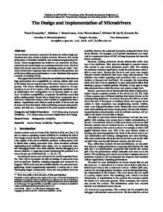
4.3 Results � QoS Broker Performance
The establishment of a resource contract for a unidirectional QoS call/connection, if one-toone translation (1-1 mapping) is performed, takes on average 60 milliseconds. Much of this time is consumed in the analysis of schedule feasibility. If the QoS Translator splits the data across VCIs (e.g., the 1-4 mapping for sensory data discussed above), the resource deal takes 24
60000 55000 45000
50000
Duration [usec]
65000
70000
an average of 67 milliseconds. The extra 7 milliseconds is a consequence of the more complex communications and QoS structure. Figure 14 shows the run-times of the QoS Broker during the negotiation process. Clearly these times are too long, but we used extremely simple algorithms with poor performance to speed up our implementation of the prototype. Unless frequent renegotiation is required, even these times should not present a problem.
1-1 Mapping
1-4 Mapping
QoS Broker with Different Mappings
Figure 14: Run-time of the QoS Broker for Sensory Data
� RTAP/RTNP Performance
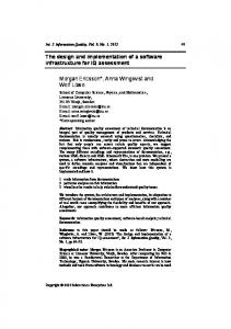
OMEGA was tested under various scenarios with di�erent combinations of sensory and video data. The RTAP/RTNP tasks performed well. The measured end-to-end delays of the sensory data for our telerobotics application are 3 ms (average value) using an ATM LAN environment [NS95], which is about a factor of 60 better than the application had previously achieved. The application subsystem had been running in user space and used TCP/IP over a lightly loaded Ethernet (180 ms!) on lightly loaded SUN(slave)/SGI(master) [Nah95] (the same restrictions were used for OMEGA measurements). Figure 15 shows the con guration of our telerobotics system with support of both systems. The performance di�erence is less due to Ethernet and TCP/IP, and more to the decoupling of the application subsystem from TCP/IP, and lack of real-time support (e.g., no ne granularity timers, and UNIX process scheduling). For the telerobotics application, the problem with delay larger than 20 ms is that the slave becomes unstable if the position information does not arrive on time and the slave does not have any information to react on. An uncontrolled slave can cause severe damage. Since the 20 ms bounds could not be met in the more communitarian environment, the older robotics system had used open-loop control with a time-delay. With OMEGA roboticists can begin to model their master/slave communication in communitarian environments as closed-loop control utilizing force feedback. When video and sensory data were transmitted together, the performance of the sensory data was poor due to late packets. We tested this scenario by disabling the admission control because otherwise the broker admission rejected it. The violation of deadlines for sensory data could be attributed to at least two bottlenecks: (1) head of line blocking (priority inversion between video packet and sensory packets) in the ATM host interface architecture caused by serial DMA of packet data for large packets; (2) display of the video frame using not-shared X 25
Operator Side
Robot Side
(master)
(slave)
Puma 250 SUN station
JIFFE station
Software&Hardware
Software&Hardware
Bus
Bus
Application Subsystem
Puma560
Robot Control
Robot Control
Application Subsystem
OMEGA
OMEGA Camera
Display
TCP/IP Ethernet Adapter
TCP/IP Ethernet Adapter
ATM Card
ATM Card
Network
Figure 15: Telerobotics System Con guration with OMEGA/ATM, resp. TCP/IP/Ethernet Sup-
port
windows. Figure 16 shows the results when 5 video frames are sent every second and sensory data are sent every 20 ms. The error rate for the sensory data due to late packets is high. Media QoS
Robotics Data 1 sample=64 bytes
(average values) End-to-End Delay Protocol Processing RTAP/RTNP
Late Packets
Transmission Interval
Video Data 1 frame = 240x160pixels 8 bits/pixel (no fragmentation)
3 ms Read/Send : 0.4 ms Recv/Write: 1.1 ms 70%
20 ms
149.5 ms Read/Send: 3.7/3.2 ms Recv/Display: 59/38 ms
0.0001%
200 ms
Figure 16: Sensory and Video Data Together There are several approaches to this problem, among which are (1) introducing priority scheduling and multiplexing into the ATM host interface, or (2) minimizing delay due to serializing. Bottleneck (1) could be solved by sending very small video fragments. However, this approach means that the very small video fragments in uence the quality of video and the user ends up with frame rate of 1 frame/second or lower which might be useless in applications such as telerobotics. Bottleneck (2) could be solved by using shared X which decreases the display time below 20 ms per frame and is necessary when sensory data are multiplexed with the video tra�c. Our 26
platform did not support shared X.
5 Conclusion The whole is more than the sum of the parts (Aristotle, Metaphysica)
Many distributed multimedia applications need system support for con gurable and adaptive behavior. Among the most important con guration support is that of application-to-application real-time guarantees. Previous to the work presented here, Quality of Service (QoS) was often believed to be purely a network phenomenon, deliverable via proper con guration of switches and other network sharing mechanisms. When an application perspective is applied, many of the QoS measures do not make sense { mainly because the network QoS is necessary, but is only part of the picture. The QoS Broker provides a method for coordinating the several layers of the system to provide end-to-end service guarantees. We have used the model of striking a deal, as it re ects the notions of negotiation and renegotiation of QoS central to adaptive applications. Where guarantees are made in the deal struck, the broker ensures that the necessary resources are guaranteed to be available at the relevant points in the end-to-end communications path. These guarantees are made possible by a robust admission service, which ensures that a feasible schedule exists for allocated resources. We noted that traditional schedulability tests were insu�cient for our environment due to their assumptions about task structure. In this paper, we showed the value of splitting the system into layers based on the nature of the QoS criteria speci ed in that layer. The layering provides two things. First, provided that there is a good understanding of the application (which may be encapsulated in application pro les), translation can be performed between speci cations of QoS. Second, the layer structure can be used to hide transparent adaptation, e.g., some of the automatic recon guration of the QoS Broker. To ensure that the transport subsystem was under scheduler control (and hence included in the QoS Broker's set of guaranteed services) we designed and implemented prototypes of a Real-Time Application Protocol and Real-Time Network Protocol. While not full-featured, these new stacks were necessary to implement a scheduled multiplexing policy, which we required for end-to-end guarantees. We have implemented a prototype of the OMEGA architecture on a dedicated 155 Mbps ATM LAN. We tested the architecture with a demanding application, that of sensory-feedback teleoperation. Our application environment tested tactile data and video feedback in the control of a Puma 560 robot arm. For a key parameter in system performance, the end-to-end delay bound observed by the application, we showed a 3 millisecond versus 180 millisecond advantage over application subsystem with TCP/IP operating on an Ethernet LAN. While some of this can be attributed to throughput, the total advantage of about 60 to 1 argues that structuring systems with resource guarantees can have signi cant advantages for applications. This was the rst telerobotics application tested over ATM, and our roboticist colleagues are enthused about these results. The prototype OMEGA implementation has limitations, varying between the trivially remedied and deep research questions. An example of the rst is pacing required by the video service due to some bugs in the ATM interface device driver. There are many limitations from the computing and communication environment. In particular, there needs to be more control of scheduling for all 27
elements of the computing system endpoint. This does not mean that all services must be allocated; rather, it means that the design must allow allocated services to e�ectively interoperate with services which can operate in a more dynamic environment. An example system containing support of several scheduling policies such as rate-monotonic algorithm, earliest deadline rst, time slicing, mixed priority scheduling, etc. is the ARTS (A Distributed Real-Time System) kernel[TM89]. Among the deepest research questions is that of renegotiation paradigms with adaptive algorithms, and mapping perceptual QoS to the kinds of algorithms and mechanisms we have discussed in this paper; we have only touched on these topics. There are several promising directions for future work stemming from our research. First, we found that the programming of systems with time constraints was clumsy. To be more precise, it required a mixture of application code and system code used to access timer services. This indicates a need for better support for time in programming languages. Such support might include ner divisions of Application QoS descriptions of media behavior rather than only strongly versus weakly periodic behavior, as well as re nements of the API for timing constraints and QoS. It would be desirable to specify more complex behaviors such as: between (t1 and t2) send data with QoS1 ; after t2 send data with QoS2 ; Experimental language support should be designed and prototyped, combining language support for QoS speci cation [FY94] and language support for time, as in Dannenberg's[Dan84] Arctic language or Lee's CSR (Communicating Shared Resources) [LDG91]. Second, while automatic management of resources can be managed by the operating system inferring application behavior, our observation is that current OS management policies do least well with the most complex multimedia application { those that in some sense push the edge. In making our observations above, we observed that there should be more scheduler control, as we found this particularly problematic. More generally, though, the question of application participation in resource management of all types needs examination by the operating systems community. One example of a useful step in this direction was given by Druschel, et al.,[DPD94] who showed the value of a di�erent perspective on bu�er management as well as direct access to device resources through protected \Application Device Channels." Finally, and extending the previous point, we think that the rebalancing of the roles of application, network and operating system should include the notion of negotiation and renegotiation. Many new systems will require adaptive behavior and we think that research should be done to identify a general kernel of functions which support this adaptation. We believe that both application adaptation to system resource changes and system adaptation to application demands must be supported. Our OMEGA architecture provides a tested framework for exible adaptive resource management. It provides automatic translation/admission/negotiation, dynamics and guarantees to networked multimedia systems. The rst successful experiments with telerobotics are encouraging, and among our future trials will be the challenge of mobile systems based on wireless networks.
28
6 Acknowledgment We gratefully acknowledge discussions with David Farber, S. Keshav, Richard Paul, Insup Lee, and Ralf Steinmetz. Brendan Traw designed the ATM infrastructure, and Drew Moore designed the G-LINK transmission systems used for our experiments. Ruzena Bajcsy, Director of Penn's GRASP Laboratory, suggested the telerobotics application. Craig Sayers, Nikolaos Fahantidis and D. Venkatesh of the GRASP laboratory helped with our understanding of the application. The anonymous reviewers provided useful technical and editorial advice.
References [And93] D. P. Anderson. Meta-Scheduling for Distributed Continuous Media. ACM Transaction on Computer Systems, 11(3), August 1993. [Bie93] E. W. Biersack. Performance Evaluation of Forward Error Correction in an ATM Environment. IEEE JSAC, 11(4):631{640, May 1993. [BM91] A. Banerjea and B. Mah. The Real-Time Channel Administration Protocol. In 2nd International Workshop on Network and Operating System for Digital Audio and Video, Heidelberg, Germany, November 1991. [CCH93] A. Campbell, G. Coulson, and D. Hutchison. A Multimedia Enhanced Transport Service in a Quality of Service Architecture. In Workshop on Network and Operating System Support for Digital Audio and Video '93, Lancaster, England, November 1993. [CT90] D.D. Clark and D.L. Tennenhouse. Architectural Considerations for a New Generation of Protocols. In ACM SIGCOMM'90, pages 200{208, Philadelphia, PA, September 2 1990. [Dan84] R.B. Dannenberg. Arctic: A Functional Language for Real-Time Control. In ACM Symposium on LISP and Functional Programming, pages 96{103, August 1984. [DPD94] P. Druschel, L.L. Peterson, and B.S. Davie. Experiences with a High-Speed Network Adaptor. In ACM SIGCOMM, pages 2{13, London, UK, September 1994. [FV90] D. Ferrari and D. C. Verma. A Scheme for Real-Time Channel Establishment in Wide-Area Networks. IEEE JSAC, 8(3):368{379, April 1990. [FY94] P.G.S. Florissi and Y. Yemini. Managing Quality of Service in QuAL. In Workshop on Distributed Multimedia Applications and Quality of Service Veri cation, Montreal, Canada, June 1994. [KS95] S. Keshav and H. Saran. Semantics and Implementation of a Native-Mode ATM Protocol Stack. Internal technical memo, AT&T Bell Laboratories, Murray Hill, NJ, January 1995. [LDG91] I. Lee, S. Davidson, and R. Gerber. Communicating Shared Resources: A Paradigm for Integrating Real-Time Speci cation and Implementation. In A.M. van Tilborg and G.M. Koob, editors, Foundations of Real-Time Computing: Formal Speci cations and Methods, pages 87{109. Kluwer Academic Press, 1991. 29
[LL73] C. L. Liu and J. W. Layland. Scheduling Algorithms for Multiprogramming in a Hard Real-Time Environment. Journal of the ACM, 20(1):46{61, January 1973. [Nah95] K. Nahrstedt. An Architecture for End-to-End Quality of Service Provision and its Experimental Validation. PhD thesis, Department of Computer and Information Science, University of Pennsylvania, August 1995. [NS94] M. Di Natale and J. A. Stankovic. Dynamic End-to-End Guarantees in Distributed RealTime Systems. In Real-Time Systems Symposium, pages 216{227, December 1994. [NS95] K. Nahrstedt and J. M. Smith. The QoS Broker. IEEE Multimedia, 2(1):53{67, Spring 1995. [PZF94] C. Parris, H. Zhang, and D. Ferrari. Dynamic Management of Guaranteed Performance Multimedia Connections. Multimedia Systems, 1(6), 1994. [R.L94] R.L.R Carmo et al. Real-Time Communication Services in a DQDB Network. In Real-Time Systems Symposium, pages 249 {258, San Juan, Puerto Rico, December 1994. [ST93] J. M. Smith and C. Brendan S. Traw. Giving Applications Access to Gbit/s Networking. IEEE Network, pages 44{52, July 1993. [TM89] H. Tokuda and C. W. Mercer. ARTS: A Distributed Real-Time Kernel. ACM Press, Operating Systems Review, 23(3):29{53, July 1989. [TS93] C. B. S. Traw and J. M. Smith. Hardware/Software Organization of a High-Performance ATM Host Interface. IEEE JSAC, Special Issue on High-Speed Computer/Network Interfaces, 11(2):240{253, February 1993.
30