Design, Implementation and Testing of a Real-Time Mobile WiMAX Testbed Featuring MIMO Technology Oriol Font-Bach1, Nikolaos Bartzoudis1, Antonio Pascual-Iserte1, 2 and David López Bueno1 1 Centre Tecnològic de Telecomunicacions de Catalunya (CTTC), Parc Mediterrani de la Tecnologia (PMT), Av. Carl Friedrich Gauss 7, 08860 Castelldefels, Barcelona, Spain 2 Dept. of Signal Theory and Communications - Universitat Politècnica de Catalunya (UPC), Campus Nord, Jordi Girona 1-3, 08034 Barcelona, Spain {ofont,nbartzoudis,dlopez}@cttc.cat -
[email protected]
Abstract. Multiple input multiple output (MIMO) is a technology that enhances wireless systems capacity, data rate, and coverage by utilizing the spatial diversity provided by multiple antennas. However, these benefits come at the expense of increased computational complexity. Implementing a broadband MIMO wireless communication system in a real-time testbed is a challenging task, entailing numerous pitfalls. This paper presents several implementation aspects of a real-time MIMO testbed based on the mobile WiMAX standard. The focus is mainly laid on the bit-intensive baseband digital signal processing at the receiver. Keywords: MIMO, testbeds, IEEE 802.16e, real-time systems, FPGAs, DSP.
1 Introduction Deploying a broadband wireless communication standard such as the IEEE 802.16e-2005 [1] (i.e., mobile WiMAX) in a real-time testbed implies several design, implementation and testing challenges, especially considering the top-up computational complexity introduced by the MIMO technology. The massive parallelism required for the baseband signal processing in real-time testbeds, makes the FPGA devices the obvious candidate for implementing such systems. The inherent processing parallelism of FPGA devices and the availability of a wide range of preverified IP-cores make them a preferable choice compared to DSP microprocessors. At the same time, the cell-processors though demonstrating a remarkable performance [2] are still considered to be an immature solution due to the C-coding parallelism limitations, the insufficient IP libraries and the lack of development boards. This paper presents the challenging and demanding task of implementing a pointto-point mobile WiMAX system in a real-time testbed having a 2x2 MIMO configuration. The system uses matrix A encoding in an open-loop configuration (i.e. without feedback), based on Alamouti's space-time block code [3] in a per carrier basis. The 20 MHz channel bandwidth of this testbed exceeds the WiMAX Forum specifications for the IEEE 802.16e-2005 standard (i.e. wave-2) positioning the ¯¯¯¯¯¯¯¯¯¯¯¯¯¯¯¯¯¯¯¯¯¯¯¯¯¯¯¯¯¯¯¯¯¯¯¯¯¯¯¯¯¯¯¯¯¯ This work was partially supported by the Catalan Government under grant 2009 SGR 891; by the Spanish Government under projects TEC2008-06327-C03 (MULTI-ADAPTIVE) and 2A103 (MIMOWA) from MEDEA+ program (AVANZA I+D TSI-020400-2009-44) and “Torres Quevedo” grants PTQ-08-01-06441, PTQ06-02-0540, PTQ06-2-0553; and by the European Commission under projects NEWCOM++ (216715) and BuNGee (248267).
system presented herein on the forefront of applied research utilizing real-time MIMO testbeds. Setting up the whole testbed is a quite hard research and engineering task. The most critical part of the mentioned development is found in the design, simulation, implementation and real-time debugging of the receiver which, for this reason, is widely detailed in this paper.
2 Short Review of MIMO Testbeds The great majority of the existing testbeds supports off-line signal processing, making use of Matlab or other signal processing software [4], [5]. Apparently, off-line testbeds are not able to process in real-time the received signals. However, their flexibility makes them appealing to researchers since such testbeds allow them to explore various real-world signal processing concepts. Their offline operation renders these testbeds incapable to explore medium access control protocols and the reception of long data frames because of timing and memory constraints, respectively. Besides, offline testbeds are not able to realize closed-loop strategies. Although we have found in the literature low-bandwidth MIMO testbeds based on the IEEE 802.11n [6] and the 802.16d standard [7], [8] (i.e. no mobility), we have not encountered literature for real-time MIMO testbeds implementing the IEEE 802.16e standard using a 20 MHz bandwidth. A combination of mobile and fixed WiMAX testbed is presented in [9]; nevertheless the scope of the project is different since commercial equipment is used to assemble the entire physical layer of the testbed. Real-time MIMO testbeds implementing the IEEE 802.16e-2005 standard are mainly deployed by industrial initiatives (e.g. Alvarion), which are currently offering bandwidths up to 10 MHz (e.g. WiMAX wave-2 specifications [1]).
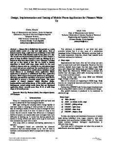
3 Description of the Experimental Setup A point-to-point MIMO testbed typically comprises i) a transmitter with baseband signal processing units, digital-to-analog converters (DACs) and RF up-converters, ii) a multi channel emulator or sets of transmit and receive antennas (indoor channel), and iii) a receiver with a series of RF down-converters, analog-to-digital converters (ADCs) and baseband digital signal processing units. A graphic-overview of our realtime mobile WiMAX testbed setup for a point-to-point 2x2 MIMO system is shown in figure 1. The parameters of the OFDM downlink (DL) frame, consisting of a single burst with a fixed predefined format (i.e, FCH and DL-MAP are not decoded), are shown in table 1 and depicted in figure 2. Taking into account the baseband sampling frequency (i.e. 22.4 MHz), the rate of Alamouti's space-time code (STC) coding (i.e. unity) and the total number of PUSC subcarriers (i.e. data+pilot+dc-carrier = 1681), the actual peak of un-coded useful data rate is 22.4 × 2 × 1 × 1681/2048 × 2048/2560 = 29.4175 Mbits/s and the spectrum efficiency for a 20 MHz channel bandwidth is 1.47 bits/Hz/s assuming the use of QPSK modulation at each data carrier.
Figure 1: CTTC’s point-to-point real time 2x2 MIMO testbed featuring mobile WiMAX. Table 1: A synopsis of system parameters. Parameter Value Wireless telecommunication standard Tx antennas x Rx antennas RF frontend operating band (GHz) IF frequency || Ch. Bandwidth (MHz) Channel models A/D sampling clock frequency (MHz) Sampling frequency Fs (MHz) Modulation type Duplex mode FFT size Supported permutation scheme Data || pilot || null subcarriers Sub-channels Subcarrier frequency spacing f (kHz) Useful symbol time || Guard time (μs) Frame duration (ms) || OFDM symbols Open loop configuration: STC type De-interleaving, Ch. coding, multiuser
IEEE 802.16e-2005 2x2 2.495 - 2.690 156.8 || 20 ITU Ped. B - Veh. A 89.6 22.4 QPSK TDD 2048 DL PUSC only 1440 || 240|| 368 60 10.94 91.4 || 22.85 5 || 48 Matrix A Alamouti not supported
Figure 2: Frame format.
MIMO Signal Transmission: The baseband part of the transmitter was designed using Matlab. The separate I and Q baseband outputs of this model (corresponding to the two transmitter’s branches) are written to data-files, which are fed to two instances of Agilent's Signal Studio Toolkit. The data-files are then uploaded to two Agilent vector signal generators (i.e. ESG4438C), which are appropriately connected for a MIMO signal transmission. This connection requires careful offline adjustments (e.g. time-alignment of the output signals). The two ESG4438C are utilizing their embedded arbitrary waveform generator to playback in real-time the baseband I and Q waveforms, up-convert the signal and finally provide the RF output centered at 2.595 GHz. The accuracy of these instruments guarantees a very high performance (e.g. excellent Error Vector Magnitude (EVM) profile). To verify the transmitter's
compliance with the IEEE 802.16e standard, we have used Agilent's Vector Signal Analyzer (VSA) to demodulate the received RF signal. The Channel: The connection between the transmitter and receiver can be done via a direct cable, over the free radio channel using antennas, or through a channel emulator. The two testing and measuring scenarios were: i) antenna transmission using an indoor radio channel, and ii) use of a channel emulator (i.e. EB Propsim C8) to generate an outdoor static or mobile channel. Measurements over the indoor radio channel were conducted only to prove functional conformity and thus they would not be analyzed herein. The channel emulator is configured with a 2x2 MIMO model, emulating the ITU Vehicular-A standard channel model (i.e. 6 tap tap-delay-line). The channel is assumed to be quasi static for the duration of an OFDM frame. The Receiver: A fully integrated, dual-band multi-channel WiFi RF transceiver [10] (i.e. designed in CTTC) was upgraded to match the WiMAX testing scenario. Certain critical building blocks were replaced (i.e. RF and IF filters, the local oscillator and the sampling frequency synthesizer). Both the WiFi operation at 2.4 GHz and the WiMAX one at 2.6 GHz performed satisfactory in a 2x2 MIMO configuration (i.e. proof of concept validation). The testbed specifications were expanded in terms of scalability and performance by acquiring high-end, multichannel broadband RF downconverters (i.e. MCS Echotek Series RF 3000T). Table 2 summarizes the main specifications of the two available RF front-end solutions. Table 2: Performance-comparison of the RF front-end solutions. Parameter
Custom receiver
COTS receiver
RF input frequency range IF output frequency range (3dB BW) Frequency resolution Internal reference accuracy Phase Noise Noise Figure Gain control range Image rejection Spurious output levels Input Third-Order Intercept Point (IIP3)
2.4-2.7GHz & 5.15-5.35 GHz 135..173 MHz