SEU Journal of Science and Engineering, Vol. 10, No. 2, December 2016
ISSN: 1999-1630
Design, Implementation and Testing of Ultrasonic High Precision Contactless Distance Measurement System Using Microcontroller Rokhsana Titlee1 and Muhibul Haque Bhuyan2* 1Department
of Electrical and Computer Engineering North South University, Bashundhara, Dhaka, Bangladesh. 2Department of Electrical and Electronic Engineering Southeast University, Tejgaon, Dhaka, Bangladesh. Abstract
This paper reports on design, implementation and testing of a ultrasonic high precision and low cost noncontact distance measurement system using microcontroller. Use of PIC16f877a microcontroller lowers the system cost and the use of ultrasonic transducer module HC-SR04 makes the system non-contact. Recommended range for the ultrasonic sensor is 2 cm to 4 m at accuracy of 3 mm. The ultrasonic module transmits ultrasonic sound waves at non-audible frequency of 40 kHz, then picks up its echo that comes from an object to the source. Time period of the output wave form is proportional to the distance between the source and the object whose distance is being measured. The microcontroller receives the output signal, performs the necessary information processing inside it and finally displays the corresponding measured distance on the LCD screen. The sample test results reveal that the system can calculate distances accurately from any object to the source of the ultrasonic wave generator between which the distances are being measured. Percentage of error is then calculated between the measured and actual distances. It is found from the performance test that the designed system works very well. Keywords: Microcontroller, Ultrasonic Wave, Contactless Distance Measurement.
I. Introduction Various industrial processes and systems require information about placement of various kinds of objects. Non-contact distance measurement systems are used for the determination of the position of the objects in many cases. There have been lots of different ways for noncontact distance measurement like laser/ infra-red optical sensor, ultrasonic technique, radar devices etc. (B. Duval, 2004), and complete measuring systems may cost some hundred dollars (S. Y. Yurish, 2009). Low cost short distance measuring systems with a price up to some tens dollars can be built based on the infrared light sources (S. Boedecker et al., 2010). Such systems are using infrared optical sensors with the output signal proportional to the distance between sensing element and object. For example, a low-cost short distance measuring system, described in (P. Arce et al., 2004) uses frequency of the output optical sensor (infrared light source and infrared light-to-frequency converter), has 35-60 mm measuring range, and from 0.25 s to 1 s measurement time. An optical sensor with
a laser source (of 532 nm) for real-time measurement of lignin content in moving paper sheets is described in (M. K. Ramasubramanian et al., 2005). Different structures of a contactless position sensor have been realized by using a magnet as the target and an inductance as the sensing element by local saturation of its core by a magnet (B. Legrand et al., 2003). A low-cost, non-contacting, nondestructive technique is presented for measuring the thickness of thin liquid or solid films and coatings in real time by utilizing the resonance properties of micro-strip structures in (L. F. Root et al., 1992). Besides, microwave based moisture sensor has been developed for the food industry (T. Hinz et al., 1996). Among the various techniques of noncontact measurement, ultrasonic technique is the best (U. Grimaldi et al., 1995 and P. Purnell et al., 2004) when we need stable and accurate distance of obstacle, no matter what color it is. It is also usable outside in the sun. As the human ear’s audible range is 20 Hz to 20 kHz, it is insensitive to ultrasonic waves, and hence
* Corresponding Author: Dr. Engr. Muhibul Haque Bhuyan, Chairman, Department of Electrical and Electronic Engineering, Southeast University, 251/A and 252,Tejgaon Industrial Area, Dhaka 1208, Email:
[email protected]
SEU Journal of Science and Engineering, Vol. 10, No. 2, December 2016
the ultrasound waves can be used for applications in industries or vehicles without hindering human/other activity. With the development of technology, microcontroller is becoming more suitable chip to control various electro-mechanical devices (M. H. Bhuyan et al., Jan 2010, M. H. Bhuyan et al., Jun 2010 and M. K. Russel et al., Dec 2012). Microcontrollers are used in automatically controlled products and devices. By reducing the size and cost, microcontrollers make it economical to digitally control even more devices and processes (M. A. Mazidi et al., 2007). This work reports a microcontroller based high precision distance measurement system using ultrasound sensor. The software is developed in such a way to get the optimum result in terms of accuracy and time consumed. This device consumes low power, is portable and cheap. From the experimental results, it is seen that the designed system works very well with high level of accuracy.
7
II. Working Principles of the System The designed system mainly consists of a 40-pin microcontroller unit (PIC16f877a), a 4- pin sonar sensor (HC-SR04), an LCD display, a 20 MHz crystal oscillator to provide clock frequency, two 22 pf capacitors etc.
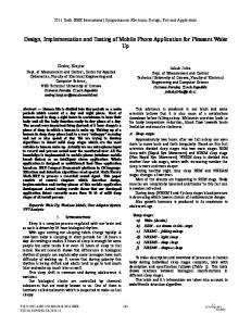
Figure1: Communication between microntroller unit and ultrasound sensor. In between HC-SR04’s timing diagram is shown
The designed system works on a similar principle of radar which evaluates the target by interpreting the echo from sound or radio waves as shown in Fig. 1.
Figure 2: Schematic diagram of microcontroller based distance measurement system using ultrasonic sound
8
SEU Journal of Science and Engineering, Vol. 10, No. 2, December 2016
The microcontroller sends 10 µs pulse to the trig pin of the ultrasonic transducer. It reads when the echo arrives; it finds the time taken in microseconds for to and from travel of sound waves using TIMER1. Using velocity of sound 340 m/s, it does the calculations and shows on the LCD module and display the distance in cm. From the timing diagram as shown in Fig. 1, we can see that the 40 kHz pulse train is transmitted just after the 10 µs triggering pulse and the echo output is obtained after some more time. The next triggering pulse can be given only after the echo is faded away, and this time period is called cycle period. The cycle period for HC-SR04 must not be below 400 µs. The complete schematic diagram of the system is shown in Fig. 2.
III. Distance Calculation The formula used for distance calculation is as follows: D = (vt)/2 (1) where D is the distance between ultrasonic sensor and target, v is the speed of sound in the air (34000 cm/s) and t is the time obtained from the microcontroller by the relationships shown in equations (2) and (3). t = (TMR1H:TMR1L)×10-6 (2) TMR1H:TMR1L = (TMR1H