Such gratings also offer a high degree of design flexibility. In the present work, ... will cause some change in the transmission or reflection from the pixel. .... free greys to be produced. 100. 1000. 15. 20. 25. 30. Voltage (V). Tim e slo t (u s). 0.6um .... G.P. Bryan-Brown, C.V. Brown, J.C. Jones, E.L Wood, I.C.. Sage, P. Brett and ...
Greyscale in Zenithal Bistable LCD: The Route to Ultra-low Power Colour Displays. J.C. Jones, S.M. Beldon and E.L. Wood ZBD Displays Limited, Malvern Hills Science Park, Malvern, Worcs, WR14 3SZ, UK
ABSTRACT Zenithal Bistable Devices (ZBD) exhibit rugged image storage, excellent optical performance, fast latching and infinite multiplexibility. These properties arise from the use of the grating layer used to align a nematic liquid crystal. Such gratings also offer a high degree of design flexibility. In the present work, grating shape is varied within each pixel to introduce error-free analogue greyscales. Passive matrix waveforms, suitable for use with commercial STN drivers are reported, and shown to produce at least 7 errorfree greys in a test cell. A method for achieving 64 static greys is described.
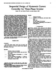
a conventional rubbed alignment surface, the device may be latched between HAN and TN configurations (Figure 1) using bipolar pulses of sufficient energy. Displays have been produced that show excellent front-of-screen performance, combined with ultra-low power and rugged image storage [5]. This is achieved using a standard 5µm cell gap, and with manufacturing tolerances closer to those of conventional TN displays, rather than STN. HAN
Keywords: LCD, bistability, greyscale, colour, ZBD. INTRODUCTION An essential part of producing colour displays is the achievement of sufficient greyscale. For example, 4096 colours require 16 separately addressable transmission (or reflection) levels. Bistable display technologies are inherently digital in nature. Full colour bistable ferroelectric liquid crystal displays have been reported: 256 greys were achieved using a combination of spatial (electrode subdivision) and temporal dither (frame subdivision) [1]. However, temporal dither requires fast operation and cannot be used in an image storage mode. A high level of spatial dither is costly, both in terms of the additional electronic drivers needed, and the electrode etching limits for the least significant bit. An analogue approach to generate the grey levels is often taken for devices such as the bistable cholesteric, in which partial latching of the pixel is used [2]. After blanking into one of the stable states, an intermediate voltage level nucleates domains of the opposite state, forming a random mixture of domains. Such an approach is sensitive to panel variations because the latching threshold is dependent on the applied voltage, cell gap and temperature. Any variation of condition across the panel will cause some change in the transmission or reflection from the pixel. To prevent overlapping grey levels, these tolerances can become very tight. For example, considering cell gap variations alone, sixteen analogue levels require cholesteric devices to be produced with tolerances of ±11 nm [3]. Bistable Twisted Nematic devices rely on obtaining the correct ratio of cell gap and helical pitch, and need tighter tolerances still to obtain reliable greyscale. Zenithal Bistable Devices [4] use a grating alignment layer to give two stable states of a nematic liquid crystal, either high or low surface tilt. When used opposite
TN AR Polariser
Bistable Surface
High Tilt State
Low Tilt State
Planar Surface
RDFB Reflective Polariser (3M)
a) b) Figure 1. Schematic of the ZBD cell configuration: a) high tilt (HAN) and b) low tilt (TN) alignment states.
ERROR-FREE GREYSCALE An important advantage of grating alignment layers is the design flexibility that they offer. The shape and alignment properties of the grating may be varied across a pixel, for example to give wide viewing angle and analogue greyscales [6]. For example, each pixel can be subdivided into a number of areas with different latching thresholds; the fraction of the pixel that changes state, and hence its transmission, is then related to the applied electrical signal. Alternatively, appropriate grating design [7], introduces further stable pre-tilts of the director and hence gives a zenithal multistable device. Both of these approaches lead to error-free greys, as shown by curve B in Figure 2. Within the limits set by the partial latching regions of adjacent thresholds, the transmission of error-free greys is independent of cell variations.
____________________________________________________________________________________________ Proceedings of the 7th Asian Symposium on Information Display (ASID ’02) ISBN: 981-04-6983-7
205
Transmission, T
threshold changed by 6 V across the window of bistability, and the partial latching width is typically 0.4 V. This means that 6 error-free analogue levels may be achieved in ZBD panels made to TN tolerances, whereas 15 error-free levels are possible if STN tolerances are maintained. Other changes to the grating shape, such as change in offset, will increase the tolerance to variations and allow further errorfree greys to be produced.
Α Β
∆Τ
1
2
1000
∆V
0.6um 0.7um 0.8um 0.9um
Data Waveform (eg. V)
Time slot (us)
Figure 2. The principle of error-free grey levels. Curve A represents a typical latching response of a domain nucleated bistable device. Slight variations in the conditions across a cell (such as ∆V) lead to relatively large transmission errors (∆T). Curve B shows the response to a similar device with an intermediate threshold level and the same partial latching width. Between voltages 1 and 2, the transmission is independent of ∆V and the grey level is error-free.
100 30
15
τ = 500µs;
20
25 C Latching Voltage (V)
25
30
Voltage (V)
0
a) 20
Pitch (nm) 600
6
V = 5 + 4x10 dTOT
700
800
900
10
0
0.0
-6
1.0x10
2.0x10
-6
-6
3.0x10
4.0x10
-6
5.0x10
-6
cell gap (dTOT) / m
Figure 3. Cell gap dependence of the ZBD latching voltage (for a 500µs bipolar pulse at 25°C).
Latching Voltage (V)
25
20
A typical ZBD cell gap dependence is shown in 20 40 60 Figure 3. Latching is a field effect (requiring 4V/µm for this % Mark to Space material) and the offset is due to the dielectric effect of the grating layer. Conventional TN requires a cell gap tolerance b) of ±0.2µm (to prevent optical variations), whereas STN Figure 4. ZBD latching characteristic as a function of grating requires lower tolerances, typically ±0.05 µm. Such cell shape. a) τV curves for a range of grating pitch. b) Latching gap deviations across a ZBD panel would change the voltage dependences on pitch and mark to space ratio. The lower latching threshold by 0.8 V and 0.2 V, respectively. Note, line represents onset of domain nucleation, and the upper line the cell gap tolerance for optical variations is the same for complete latching. ZBD as TN. There are several practical options for varying the GREYSCALE ADDRESSING USING COMMERCIAL latching threshold of the grating, including changes of STN DRIVERS pitch, amplitude, mark to space ratio and offset. Test cells Although commercially preferable, the use of STN drivers were fabricated using sub-pixels with pitches in the range constrains the addressing schemes that can be used to drive 0.6µm to 1.0µm, and mark to space ratios from 22% to a bistable display. For example, the drivers are usually 64%, whilst keeping amplitude and offset fixed. The restricted to five voltage levels (e.g. 0, ±Vs and ±Vd), latching threshold characteristics for these cells are shown wherein the data voltage, Vd ≤ 7 V but cannot include in Figure 4. Excellent bistability was maintained across this periods of 0 V. This means that amplitude modulated data range of grating shapes: the latching energy reduced waveforms are unsuitable for selecting the required grey approximately linearly with decreasing pitch, and increased level. Moreover, the waveforms should be DC balanced with decreasing mark to space ratio. The ZBD latching ____________________________________________________________________________________________ Proceedings of the 7th Asian Symposium on Information Display (ASID ’02) ISBN: 981-04-6983-7
206
Table 1. Example data waveforms for a six slot scheme suitable for addressing analogue levels when combined with the bipolar strobe (+++/---)Vs.
Number
Data waveform (…/…)Vd
1 2 3 4 5 6 7 8 9 10 11 12 13 14 15 16 17 18 19 20
+++/---++/--+ -++/-++-+/--+ +-+/-+--+/-++ ++-/--+ ++-/-+-+-/-++ +--/-++ -++/+-+-+/+---+/+-+ --+/++++-/+--+-/+-+ +--/+-+ -+-/+++--/++---/+++
Maximum Voltage swing (V) 2(Vs-Vd) 2(Vs-Vd) 2(Vs-Vd) 2(Vs-Vd) 2(Vs-Vd) 2(Vs-Vd) 2Vs 2Vs 2Vs 2Vs 2Vs 2Vs 2Vs 2Vs 2(Vs+Vd) 2(Vs+Vd) 2(Vs+Vd) 2(Vs+Vd) 2(Vs+Vd) 2(Vs+Vd)
Trailing pulse energy factor -3 -1 -1 -1 -1 +1 -1 -1 +1 +1 -1 -1 +1 +1 -1 +1 +1 +1 +1 +3
possible. This occurs when the latching energy (e.g. Vs) is a linear function of the applied waveform. Figure 5 shows typical results for the six-slot scheme. The limited number of permutations of the four-slot scheme did not give sufficient flexibility to ensure linearity of the greyscale response. Two aspects of the resultant waveform shape effect the latching: the select (trailing) pulse energy and the maximum voltage swing. The swing has the larger effect on latching voltage, but the smaller effect of trailing pulse energy allows fine-tuning to ensure the linearity. Figure 6 illustrates the optical response for 5 transitions induced in a pixel sub-divided into 8 areas of different grating shapes by changing the pulse amplitude. Figure 7 includes photomicrographs of this device addressed using the multiplexing waveforms of table 1. This clearly illustrates that at least 6 separately addressable areas may be discriminated using waveforms readily produced using conventional STN drivers. The lack of partial latching in each case is indicative of the error-free nature of these transmission levels. Of course, it is also possible to achieve many more greys by partially latching each of the sub-divisions. Such levels, however, will not be error-free, and will change with panel variations in a similar fashion to that of a cholesteric device.
Transmission (a.u.)
within each line address time because ZBD response to the polarity of the applied signal. The approach taken in the present work was to use either four or six time slots for each addressed line. A bipolar strobe signal of either (++/--)Vs or (+++/---)Vs was applied to the addressed row synchronously with the appropriate data waveform on the columns. All other rows were set at 0 V. With the four slot schemes, there are 6 permutations of data waveform: (++/--)Vd, (+-/-+)Vd, (+/+-)Vd, (-+/+-)Vd, (-+/-+)Vd and (--/++)Vd. With the six slot schemes, there are 20 data waveform permutations, as listed in Table 1.
25
30
35
Voltage (V) Figure 6. Pixel transmission versus addressing pulse amplitude. (τ = 50µs, T = 25ºC)
0
1
2
3
data 2
data 4
data 13
Latching onset Full Latching 20
data 1
4
Vs (V)
7
8
15
Vd = 4 V 0
5
10
15
20
Data Waveform
Figure 5. Latching Voltage as a function of data waveform for the six-slot scheme of Table 1.
data 17
data 19
data 20
Figure 7. Photo-micrographs of a pixel divided into 8 latchable areas (of which 6 are non-degenerate), together with the data waveforms used to generate the patterns. (τ=30µs, Vs=24V Vd=4V).
To help ensure each of the required greys is achieved, the operating window for each must be as wide as ____________________________________________________________________________________________ Proceedings of the 7th Asian Symposium on Information Display (ASID ’02) ISBN: 981-04-6983-7
207
38µm
152µm Grating shape 1
Grating shape 2
200 µm
Grating shape 3
1:
1
0.75 Transmission
ACHIEVING HIGH NUMBERS OF GREYSCALE Significantly more greys can be achieved using only two bits of spatial dither. Linearly spaced levels without redundancy are possible using an appropriate weighting factor for each of the digital bits. With n analogue levels, the sub-pixels should be weighted 1 : n : n2 …n(a-1), thereby giving a total of na levels [8]. For example, 16 levels are possible with 2 bits of spatial dither (a=2) and four analogue levels by weighting the sub-pixels in areas of 1 : 4, as shown in figure 8. For a 210 µm square pixel, this requires a 38µm wide least significant bit, and three grating areas of 67µm width (assuming a 10µm inter-pixel gap). Although 64 levels are possible from only 8 analogue levels, the narrow width of the least significant bit required (21µm for the example of figure 8) may be impractical to fabricate and address. In this instance, it may be preferable to use a lower spatial dither weighting and thereby introduce redundant greys, as shown in Figure 9. For example, the combination of 8 analogue levels and 1:4 spatial dither gives 36 separate grey levels. Moreover, offsetting the digital weighting slightly reduces the degree of redundancy.
0.5
Spatial Dither Weighting
4
0.25
6 8 0 0
16 32 48 Sub-pixel combination
64
Figure 9. Effect of different sub-pixel weighting factors on the greyscale characteristic.
CONCLUSION Error-free grey levels are easily introduced in ZBD devices without extra cost to the panel, as STN drivers may still be used and the extra-complexity is put into the grating production. Much higher levels of greyscales are possible when error containing greys are also used, and in combination with spatial dither. In the future, we will describe methods [9] by which the extra electrodes used in spatial dither can be driven without increasing driver requirements.
ACKNOWLEDGEMENTS The authors wish to thank their colleagues at ZBD Displays Limited.
4
a)
b) Figure 8. Optimum pixel design for achieving 16 error-free grey levels, by combining four analogue levels with 2 bits of spatial dither.
REFERENCES 1. N. Itoh, et. al. “17” Video-rate Full-color FLCD”, Proc. 5th International Displays Workshops, Kobe, Japan, pp205 – 208. (1998) 2. X-Y. Huang, N. Miller, A. Khan, D. Davis, J.W. Doane and D-K. Yang, “Gray scale of bistable reflective cholesteric displays”, Proc. SID XXIX, LP.1, pp 810 – 813 (1998) 3. P. Slikkerveer, G. Nisato, N. Koovman, P. Cirkel and P. Bouten, “A fully flexible cholesteric LC matrix display”, Proc. SID XXXIII, 5.2, pp 27 - 29 (2002). 4. G.P. Bryan-Brown, C.V. Brown, J.C. Jones, E.L Wood, I.C. Sage, P. Brett and J. Rudin, “Grating Aligned Bistable Nematic Device”, Proc. SID XXVIII, 5.3,pp 37 - 40 (1997). 5. E.L. Wood, G.P. Bryan-Brown, P. Brett, A. Graham, J.C. Jones and J.R. Hughes, (2000), “Zenithal bistable device (ZBD) suitable for portable applications”, Proceedings of SID, 2000, v31, 11.2, p124 – 127. 6. G.P. Bryan-Brown, E.L Wood and J.C. Jones, “Optimisation of the Zenithal Bistable Nematic Liquid Crystal Device” Proceedings of IDRC, Seoul, Korea, pp 1051-1053 (1998). 7. E.L Wood, G.P. Bryan-Brown, V.C. Hui, J.C. Jones and C.V. Brown, “Multistable Nematic Device”, Patent Application. 8. J.C. Jones and J.R. Hughes, US Patent 6,094,187 (1996). 9. J.C. Jones, Patent Application.
____________________________________________________________________________________________ Proceedings of the 7th Asian Symposium on Information Display (ASID ’02) ISBN: 981-04-6983-7
208