CRAM may be sufficient to achieve the performance close to 0.5 petaflops for computationally intensive program kernels. COOL-0 would occupy a physical ...
IEEE TRANSACTIONS ON APPLIED SUPERCONDUCTIVITY, VOL. 9, No. 2, JUNE 19951
3606
COOL-0: Design of an RSFQ Subsystem for Petaflops Computing Mikhail Dorojevets, Paul Bunyk, Dmitri Zinoviev, and Konstantin Likharev State University of New York, Stony Brook, NY 11794 Abstract-We discuss a preliminary design of a Rapid SingleFlux-Quantum (RSFQ) subsystem for general-purpose computers with petaflops-scale performance. The subsystem is being developed at Stony Brook within the framework of the Hybrid Technology MultiThreading (HTMT) project. COOL-0 design is based on 0.8-pm RSFQ technology which enables the implementation of superconductor processing elements (SPELLS) operating at clock frequencies up to 100 GHz, pipelined cryo-memory(CRAM) with 30 ps cycle time and interprocessor network (CNET) with a bandwidth of 30 Gbps per channel. The main architectural challenge is an almost 1,000fold speed difference between the RSFQ processors and roomtemperature SRAM comprising the second level of the HTMT memory hierarchy. The proposed solution to the problem is hardware support for two-level multithreading and block transfer techniques in SPELLS.Our preliminary estimates show that an RSFQ subsystem with 4K SPELLS and a 4-Gbyte CRAM may be sufficient to achieve the performance close to 0.5 petaflops for computationally intensive program kernels. COOL-0 would occupy a physical space of about 0.5 m3 and dissipate power as low as 250 Watts (at helium temperature). These numbers present a dramatic improvement compared to a hypothetical purely-semiconductorpetaflops-scale computer.
I. INTRODUCTION The development of digital superconductor technology is dominated presently by RSFQ logic [l], [2] because of its two unique features: very high speed (up to 750 GHz [3]), and extremely low power consumption (below 100 nW/gate [4]). In addition to these advantages, unlike latching Josephson junction devices, RSFQ circuits require only a dc power supply. Also, in comparison with CMOS, RSFQ fabrication technology using low temperature superconductors (e.g., niobium) is relatively simple, especially since it does not require deep-submicron patterning. Though RSFQ-based systems may win several special application niches, notably including high-resolution analogto-digital and digital-to-analog conversion, and digital SQUID magnetometry [l], [2] the necessity of deep refrigeration of RSFQ circuits does not allow this technology to compete with CMOS for most digital electronic applications. However, in high-performance computer systems, the refrigeration costs would be a negligible component of the total cost and the advantages of RSFQ may shine bright. Manuscriptreceived September 15, 1998.
This work was supported in part by DARPA, NSA, and NASA via JPL, and by NSF under grant No. ECS-9700313.
1051-8223/99$10.00
High performance computing is high again on the US national agenda. A recent report by the President's Informational Technology Advisory Committee (PITAC) [5 I has named high-end computing one of four key IT areas to be supported by the federal government. In particular, it recommends establishing "an initiative to reach a petaflops/petaops sustained performance on real applications" by the end of the next decade. A list of possible tasks for petaflops-scale computing (1 petaflops = 1015floating point operations per second) includes nuclear stockpilt: stewardship, fluid dynamics modeling for aerospace system development, chemical reaction simulation for new drug design, climate modeling for longer-term weather forecasts, and global economy modeling. Let us see what it would take to reach the ambitious goal of petaflops computing using CMOS technology which will be available by the middle of the next decade. According to the most authoritative industrial forecast [6], by the year 2006 high-performance microprocessors may reach a clock frequency of 2 to 3.5 GHz, and feature up to 200 million transistors on -5 an2 chips consuming power up to 160 W each. The peak perfomance of such a multiprocessor CMOS chip can be crudely estimated as 10 to 20 Gflops. Hence, to achieve a peak performance of 1 petaflops will take 50 to 100 thousand chips such as this, with a total power consumptiori of the order of 10 MW. The management of power of such proportions would take not just a large room but a sizeable: building. We would like to stress that even this discouraging estimate stems from a very optimistic assumption of 70-nm fabrication technology, for which there are "no known solutions" [6]. Moreover, the significant (300-ns-scale) latency of interprocessor communication in a system of such a physical size makes the system prone to stalling for programs where inter-processor communication and. synchronization is a large enough fraction of the computation process. These problems associated with semiconductor processors have stimulated a search for alternative approaches to petaflops-scale computing. In particular, we are participating in the Hybrid Technology MultiThreaded architecture (HTMT) project led by Jet Propulsion Laboratory [7], [8]. The goal of this project is to carry out a preliminary study of a computer architecture and functional organization of a system that would utilize novel electronic and optoelectronic technologies to achieve petaflops-level performance by or soon after year 2005. The HTMT concept assumes a hierarchical organization of the petaflops 0 1999 IEEE
3607
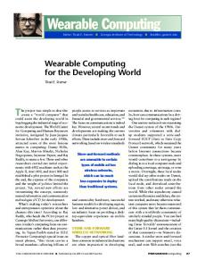
computing system (Fig. 1) with multiple levels of distributed memory: holographic data storage (HRAM), semiconductor SRAM and DRAM, and cryomemory (CRAM), as well as three types of processors: SRAM- and DRAM-based processors-in-memory (PIMs) operating at room temperature, and RSFQ superconductor processing elements (SPELLS) operating at liquid helium temperature. Thus, the HTMT project places RSFQ logic at the heart of the petatlops system as its main means of number crunching, as well as switching and routing in intra-processor and inter-processor communication networks.
DRAM PIMs
SPEWCRAM Modules
LHe
Fig. 1. HTMT computer concept. (Adapted from [7, 81).
The design of the HTMT RSFQ subsystem is far firom trivial. The time-of-flightof a signal over a 1 cm distance on an RSFQ chip is about 70 ps. This is why these circuits, operating with a few-ps clock cycle, are essentially relativistic: two gates on the same chip may be well outside each other's light cone. At such a speed, unavoidable picosecond-scale clock skew makes global timing impossible, forcing the reconsideration of almost all of standard microprocessor design techniques. Another problem stemming from the unparalleled speed of RSFQ logic is how to hide the enormous memory latency visible to SPELL processors. This latency varies from -30 processor cycles when accessing the local CRAM to -1,000 cycles when accessing SRAM. The objective of this paper is to describe in brief our initial design (which we call COOL-O) of the RSFQ subsystem [9]. Since a new design (COOL-1) is under development, all the solutions and numbers quoted below should be considered as preliminary. '
II.MULTITHREADING, HTMT PXM, AND COOL ISA A powerful method of hiding latency is multithreading. This technique reduces the processor idle time by overlapping
the execution of separate tasks called threads. Multithreaded architectures have been studied since the 1960s when the technique was first implemented in the peripheral processors of the CDC 6600. Several high-performance multithreaded computers, including HEP [lo], MARS-M [ll], and Tera, [12] have actually been built, and the concept of multithreading has been studied in several research projects [13-161. Multithreading and context prefetching have been accepted as the key techniques of latency tolerance in the HTMT program execution model (PXM) [17]. In this model, PIMs perform pre-processing of a program to find ready threads, allocate the context of a ready thread in CRAM, and initiate its execution in a SPELL. When a SPELL finishes the execution of a thread, an SRAM PIM fetches the results fiom CRAM into SRAM and transfers them to the D W H R A M level if necessary. All of these multilevel activities (searching for ready threads, pre-allocating thread contexts in CRAM, executing threads in SPELLS, and transferring data from CRAM to SRAM) can be performed in parallel provided there is enough parallelism in the programs. In fact, the HTMT PXM exposes and exploits two types of parallelism: 0 coarse-grain parallelism represented by threads (which are essentially parallel function/procedure/process invocations), 0 medium-grain parallelism represented by program entities called strands inside threads (e.g., parallel loop iterations). This two-level multithreading manifests itself in the COOL-0 instruction set architecture (ISA) developed for SPELL processors [18]. COOL-0 is a parallel 64-bit RISC architecture with the support for two-level simultaneous multithreading and pseudo-vector computation. The latter is instrumented with so-called quad instructions, each of which is able to perform operations on short 4-word vectors. In contrast to truly vector architectures, COOL-0 ISA does not rely on any vector registers. Input/output operands of the quad operations are to be fetched kom or placed into four adjacent data registers. 111. RSFQ LSI CIRCUITDESIGNPRINCIPLES The main peculiarity of RSFQ circuits from the point of view of computer design is that most Boolean logic functions (NOT, AND, etc.) are performed by "elementary cells" [l]. Functionally, such a cell may be considered as a "latching gate", an indivisible combination of a combinational logic gate and an output latch. Depending on the design tasks,this feature may be considered either as a blessing or a handicap. On the positive side, it gives latches for free. For a singlecycle pipeline, however, this feature limits the number of
3608
logic levels per pipeline stage to 1 (compared to 5-10 levels in a typical CMOS design) if only the elementary cells are used. Fortunately, two more elementary components are available in RSFQ. Some of the logic functions (for example, OR 1191) may be carried out by asynchronous circuits which resemble traditional combinational logic. Moreover, such operations as signal fork and join are also performed by simple asynchronous circuits [l]. Finally, an important contribution to RSFQ circuit latency may be given by passive (microstrip) and active (JTL) interconnects, which may also be considered as asynchronous components. ?he timing characteristics of the elementary cells and asynchronous components, and hence their possible use for pipelining, differ significantly. An elementary cell may only be occupied by one bit of data, and the next data may enter only after the gate has been cleared by a clock pulse signifying the end of the clock period. The minimum acceptable clock period T is determined by the shape of the RSFQ pulse tails, plus a necessary allowance for effects of thermal fluctuations and local variations of Josephson junction parameters. For the 0 . 8 - p RSFQ technology planned for an RSFQ petaflops computer, the minimum acceptable value of T, which guarantees an acceptable bit error rate and reasonable fabrication yield, is between 8 and 15 ps [19, 201. On the other hand, asynchronous components (including transmission lines) may allow multiple SFQ pulses to travel close to each other without any harmful interference. The minimum interval z between these pulses is considerably less than T (for the 0 . 8 - p technology, close to 3 ps). This means that these components may be used when necessary as singlebit pipelined FIFO queues. A disadvantage of this approach is that the transmission along the non-latching components Cannot be controlled btom outside with any clock signal. These RSFQ features create an unusual and substantial difference between the notions of clock cycle period and latency in instruction pipelines. The traditional RISC CMOS pipeline is divided into stages which are separated by latches, so that the signal delay (latency) L per stage equals the clock period T. An RSFQ pipeline consists of macrostages, each similar in function to the traditional RISC stage. Each macrostage, however, is composed of several microstages, each usually including one latching gate, non-latching components, and transmission lines. (We call this ultrapipelining.) As a result, the latency of each macrostage can be presented as L = nLxT + ~ A X T+ ah, where n~ is the number of microstages, nA the number of non-latching components in the critical path, a the physical length of the path, and v the speed of propagation of SFQ pulses along passive microstrip lines (-0.4 of the speed of light). Even if the last two components are negligible, the ratio U T is at least n~ >> 1. For example, recent studies of various RSFQ designs for integer adders [19, 201 have shown that a 32-bit Kogge-Stone carry-lookahead adder implemented with 0.8-
pn technology has L between 250 and 350 ps, giving the U T ratio somewhere between 20 and 40,depending on the timing technique employed. This ratio represents the required number of independent instructions needed to fill one pipeline macrostage (e.g., Integer Execute with the adder) in order to achieve its peak performance. The loadstore and floating-point pipelines will need even more instructions to reach their peak rates. This level of parallelism can be found almost exclusively in scientific programs working with regularly-structured data objects. Thus, the capability of issuing multiple instructions during loop (or vector) processing of such data objects is a critical requirement for RSFQ processors. The solutions for 100-GHz-scale RSFQ processors, however, cannot be the same as those for superscalar or VLIW processors (like loop unrolling, software pipelining, etc.). The lack of a global clock makes non-local synchronization among instructions impractical and, as a result, the implementation of compilercontrolled, synchronous VLIW computation unrealistic. The complexity of even moderate multi-way superscalar implementation is also prohibitive. The proposed design solution is to make each integer unit pipeline of any SPELL shareable among multiple strands, i.e. low-level instruction streams running simultaneously within each (higher-level) parallel thread. Because floating-point pipelines are longer and need more instmctions to be filled out, all floating-point units of a SPELL are shared by all instruction streams of all threads running in parallel within a processor. Finally, each CRAM component is made accessible to any instruction stream running in the whole RSFQ subsystem, though we expect data traffic between SPELLSand their local CRAMSto be prevailing.
IV.RSFQ TECHNOLOGY ASSUMPTIONS Niobium-trilayer RSFQ technology with 0.8 p minimum Josephson junction size and critical current density of 20 kA/cm2has been accepted as the target technology for the full-scale petaflops system. So far the most complex RSFQ integrated circuits (of up to several thousand Josephson junctions) have been built using a commercially available 3.5 pn fabrication technology [21], allowing a maximum clock frequency of about 30 GHZ. RSFQ circuits, however, obey simple scaling rules that have been confved in experiments with 3 . 5 - p , 1 . 5 - p and 0 . 5 - p devices [l][4]. This scaling shows that VLSI circuits implemented with 0.8-pn RSFQ technology should have the following major characteristics: 0 an on-chip clock rate from 60 to 120 GHz, with power dissipation of 100 nW per logic gate, and memory cycle of 30 ps (for 128x64 bit banks), with power consumption of 3 nW per memory cell.
3609
A more advanced, mid-submicron (say, 0.4 pn) RSFQ technology would allow a modest, 50% increase in circuit performance, but a dramatic (10-fold) increase in circuit density, because Josephson junctions of this size become intrinsically overdamped and bulky external shunts are no longer necessary [l].It has been decided, however, to base our initial design on the more conservative, 0 . 8 - p technology, for two reasons. First, the behavior of Josephson
junctions with critical current density beyond 20 kA/cm2 deviates substantially from the classical Werthamer model see, e.g., [3], [22]. Despite the considerable recent progress in the theory of such junctions [23] and their applications in simple RSFQ circuits [3], the manufacturability of VLSI circuits using them cannot be guaranteed before more comprehensive studies of the Josephson junction fabrication statistics have been carried out.
I
1
I
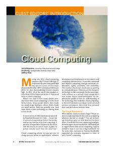
remote SPELLS,CRAMS,and SRAM PIMs Fig. 2. Top structure of the superconductor microprocessor (SPELL) in COOL-0 design. Floating point functional unit set includes adders, multipliers, a divider, and a convert unit.
361 0
Second, the 0 . 8 - p technology. is sufficient to reach petaflops performance in a system of a reasonable size (see below), while the patterning equipment for such design rules is presently very inexpensive. As a result, a pilot line for the 0.8-pm fabrication technology may be available on a very short time scale (3 to 4 years fiom now), with an estimated investment of about $20M [25] or $30M [26], very small indeed on the semiconductor electronics scale. We have assumed a (physically feasible) integration scale of 3 million Josephson junctions (about 300K elementary cells) per 4-cm2 logic chip and 10 million junctions per memory chip of the same size, at 4 superconductor (Nb) wiring layers.
V. SPELL ORGANIZATION
Figure 2 shows a block diagram of the proposed RSFQ processor. In order to organize the instruction streams so that all functional units can operate in parallel, each SPELL has 16 multi-stream units (MSU). Each MSU executes all integer, control, and floating-point compare operations of one thread, using a @-bit integer functional unit and eight 32-bit branch units sharing a 32-bit address adder, all operating with 15-ps cycle. Each SPELL has 5 arithmetic floating-point functional units (FPUs) operating with an average cycle time about 15 ps, altogether providing peak performance close to 0.3 Tflops per SPELL. MSUs can communicate with the floating-point functional units and processor-memory interface (PMI) via an. intra-processor network (PNET). Thus, the floatingpoint units and CRAM are shared resources for all instruction streams from 16 MSUs within each SPELL. 16 MSUs of a SPELL are combined into 4 MSU clusters, each with an 8-IU3 multi-port instruction cache (IC) shared by 4 MSUs within the cluster. Such shared instruction caches are beneficial when several threads work with the same code, because only one copy of the code needs to be fetched from CRAM into IC. The PNET connects MSUs, FPUs, and PMI together by handling -85bit-wide communication links through which these units can send packets to each other. This RSFQ-based switching, self-routing network uses a backpressure mechanism to resolve conflicts and to buffer requesdresponse packets in the PNET internal nodes. This mechanism prevents any packet Erom either leaving the network until a recipient outside PNET (e.g., an FPU) is able to accept it, or entering the PNET if it is congested. PNET has 32 two-way I/O ports: 16 to MSUs, 5 to FPUs, and 11 to the processor-memory interface (PMI), all operating at 30 Gbps. This speed is limited both by the inductance of chip-to-MCM pins (see below), and by the speed of message address decoding and routing. The processor-memory interface works at the same speed,
-
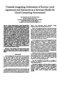
providing peak bandwidths of 8 packets each direction p a 30-ps cycle to local CRAM, 2 words to local SRAM (via the room-temperature interface), and 1 word to remote SRAM and computing modules (via CNET). Figure 3 shows the structure of the SPELL instruction pipeline consisting of a MSU datapath, PNET, CRAM and FPUs. As in a simple RISC processor, the instruction pipeline is divided into five stages (here, macrostages). In contrast to the CMOS pipeline design, each macrostage js divided into several (up to 30) microstages, and up to 8 instruction streams can run simultaneously within each MSU datapath. Except for the Memory AccessFP Execute macrostage, only instructions from different instruction streams (strands) can be simultaneously processed within each macrostage. Enforcement of this rule is possible without a big loss of throughput, because the time-of-flight of a synchronization signal over the length of one macrostage is considerably less than the stage latency L. Each MSU includes a unified set of 64 data registers, each of which is able to hold either @-bit long integer or double-precision floating-point data in the IEEE 754 format. There are also 32 4-bit condition registers used for control transfer, and miscellaneous registers for thread control, synchronization, and exception handling. Instruction streams within each MSU can share the 64 data registers, the instruction cache, and the integer functional unit. Hardware reserved for each strand includes a program counter, instruction register with strand control logic, 4 condition registers, and reservation stations where operations and their input operands are placed before issuing them to integedfloating-point units and memory. The MSU components are connected by multiplexing/demultiplexing networks that are very similar to PNET in structure and functions. Messages from different streams have no compiler-assignedpriorities, and a local first-come-first-servedpolicy with a backpressure mechanism is used in all network switches to resolve conflicts during the message routing. A branchhead control unit (BTU) always begins execution of any thread in MSU fiom strand SO, using the initial instruction address loaded fiom CRAM. (It is placed into CRAM as part of a thread control block. prepared by SRAM PIM.) Creation and termination of other strands is carried out using special "create/terminate strand" instructions and requires neither involvement of the runtime system nor allocation of any CRAM resources. There are no hardware limits (besides the number of available registers) on the number of outstanding memory references from each strand. The only reason for an individual strand to be suspended by the hardware is the detection of a datakontrol hazard in the SPELL pipeline. All types of dependencies (flow, anti- and output data dependencies) among instructions are enforced by
3611
distributed scoreboard-like logic that sets/clears a Wait bit associated with each data or condition register. When an operation is issued, its destination register is marked as
"not ready" by setting its Wait bit to 1. When the result is written into the register, its Wait bit is cleared (set to 0).
Multi-Stream Unit (MSU)
.......................................................
Instruction Fetch
InstructionDecode/
Next PC
Integer Execute1 Floating Point Compare/ Address Calculate
Memory Access/ Floating Point Execute/
Figure 3. SPELL instruction pipeline mapped onto the top structure of the multi-stream unit (MSU) in COOL-0 design. The shaded components are shared by all strands of the unit, while the systems in double frames are located outside of the MSU and shared by all threads of the SPELL. The last stage of the pipeline (Write Back) is indicated by dashed lines.
GHz ac power supply. Estimates show that the memory matrix clock cycle may be close to 30 ps. Two other important components of the RSFQ subsystem Each U 0 port operating at 30 Gbps per channel serves a are CRAM and CNET. Data storage in CRAM is based on cluster of 128 memory banks. The whole cluster operates in tbe single flux quanta coding, with the memory cell structure micropipelined mode. The role of the column decoder which very close to that developed earlier by NEC [27]. The selects one of the banks is played by a fast 1:128 memory cells are organized in 128x64-bit matrices, with one demultiplexer based on a tree of SFQ splitters followed by 64-bit word occupying an entire row of this "bank" (Fig. 4). row of 128 selectors. Each selector triggers an operation on The cells are driven by .current levels in vertical and the corresponding bank only if the address in the package horizontal lines of the matrix (rather than picosecond SFQ coincides with the bank number. In this case the header is pulses), which are generated by latching drivers. The latching promoted to the row decoding stage which is carried out by a mode, while not providing such high speed and low power as 7-stage RSFQ decoder. The corresponding data delay is RSFQ logic, is more convenient in memory cell matrices provided by special pipelined buffers (Fig. 4).Together with where speed is essentially limited by time-of-flight, and PNET and processor-memory interface delays, the local power consumption is low in any case. However, in contrast CRAM latency as seen by instruction streams is about 400 ps. to the NEC design, our cell readout interferometers use Each CRAM chip has 2 memory clusters. Each SPELL is overdamped Josephson junctions, drivers are based of served by 4 local CRAM chips, i.e. 8 clusters (256 KB per HUFFLE-style circuits, and decoders are based on RSFQ chip, i.e. 1 MB per SPELL), so that the total volume of logic. This should make it possible to avoid using a multi- CRAM in the 4K-processor system is 4 GB.
3612
The communication between each SPELLKRAM module and "local" (assigned) SRAM is provided through a roomtemperature interface with 2K wires with 8 Gbps bandwidth each. This yields a bandwidth of 1 bit-parallel packet every 30 ps in each direction per each local link, 1/8 of the SPELLto-CRAM bandwidth. The peer-to-peer and remote SRAM communications will be provided by a special digital switching network, CNET, handing 85-bit packets at a 30 GHz rate. Preliminary simulation results [27] show that CNET, implemented as
either a multi-dimensionalpruned mesh or a banyan network of 24,576 elementary 2x2 switches with credit-based flow control, may provide. a bandwidth above 0.5 words pea SPELL per cycle. Its RSFQ-based switching nodes would require just 50K to 90K Josephson junctions each, so that the total number of junctions in CNET is only a tiny fraction of all Josephson hardware of the system. On the other hand, the total wiring area necessary for CNET is very substantial (see below).
data and address in (0:84)
c
cp
0
Y
8
3
ack and/or data out (084)
Fig. 4. Block structure of one COOL-0 CRAM cluster with 128 memory banks, 8Kbits each.
VII.
PHYSICAL STRUCTURE AND ESTIMATED
PARAMETERS Physically, each processing module (SPELL with its local CRAM) of the RSFQ subsystem can be implemented as a set of seven 2x2 cm2chips including: 0 two double-cluster MSU chips, each with 2.8M Josephson junctions, 4,000 contact pads, and 24 mW of power dissipation, 0 one chip housing 6 floating-point functional units, processor-memory interface, and PNET, totaling 1.6M Josephson junctions, 6,000 contact pads, and 16 mW of power dissipation,
0
four CRAM chips, each with 10M junctions and 3,200 contact pads, dissipating 4 mW of power. The chips should be flip-chip mounted on a 20x20 cm'!
cry0 multi-chip module (CMCM). Such CMCM is large
enough to house 8 processing modules plus its share of CNET chips (see Fig. 5). Physically, CMCM is just a silicon wafer fabricated using the same niobium-basedprocess, but without Josephson junctions: it only carries two layers of 3-p-wide, 12-pn-pitch superconducting microstrip lines and 50-pmsize, 100-pm-pitch contact pads, both internal (for chip mounting) and external (leading to room-temperature interface and other CMCMs via CNET). (Approximately 25% of the wiring and 60% of the external contact pads belong to
3613
CNET, the rest to the room temperature interface). The absence of Josephson junctions on CMCM gives the hope that they may be fabricated from 30-cm silicon wafers with
..... :.. :..:~do;~;tleir;p+~-tpi+ ... -$$Q:&+ tigq .:.. ..: A . . ..
. . ..
..
.. .. .. . .. ...
. .. .
..
*.:. .
. . ..
SPELL/
..
20
..
. . ..
approximately 0.3 Mw, on the same scale as a present-day supercomputer facility with a sub-teraflops performance. Notice that the refrigeration power would be released in the helium liquefier/recondenser which can be remote, and does not affect the RSFQ chip packaging density. Figure 6 shows that the whole petaflops RSFQ subsystem will occupy a volume about 0.5 m3, apparently a small fraction of the total volume of the petaflops computing facility as a whole. This compactness of the RSFQ core would reduce the interprocessor communication latency below 20 ns, even including the CNET switching delays [28]. This speed may have important implications for sustaining near-peak performance on real-world computational problems. However, only direct simulations of the system may give a reliable prediction of the performance.
cm
VIII. CONCLUSIONS
..
. . .. . . .. . . .. . . . . . . . . ...... . . . . . . . . . . . . . . . .. . ...... *..'.. , , . . . .. .. .. .. ..' CEll3T %teff& W .(z$K.): a:.
~
~~
T
5. Floor plan of the cry0 multi-chip module (CMCM) in COOL-1 design.
Fig.
All 512 CMCMs of a petaflops computer are to be mounted vertically around an octagonal prism [%I - see Fig. 7. The interior of this cylinder will be occupied by 160 cryoprinted-circuit-board (CPCB) "pancakes" carrying 85-bitparallel CNET packets between CMCMs. With 5-layer, 100pm pitch, lead-plated copper wiring providing 8-Gbps bandwidth, the necessary wiring area is about 40% of the total area of the CPCBs [27]. The RSFQ circuits on each CMCM would dissipate -0.5 W power, on the average about 1 mW per one an2of CMCM surface. This power is far below the helium boiling threshold (-300 mW/cm2) and can be readily carried out by a slow (-1 mmls) laminar flow of helium up through the 1.3-cm gaps between CMCMs, with acceptable 1-Kelvin temperature gradient along the 0.8-m height of the RSFQ core. The power dissipated in a superconductor circuit is a factor of 3 less than the estimated thermal load imposed by 16K copper wires going from each CMCM to the room-temperature interface (at 0.1 mW per a 50-pn-diameter wire necessary to support the 8 Gbps bandwidth.) The latter number might be dramatically reduced using high temperature superconductor interconnects between the 4 K and 77 K stages of the cryostat. However, even with the current conservative assumption of copper wires, the overall power load at 4K is about 1 kW. For this power level, the efficiency of existing helium recondensers (-3OOW/W, or about 20% of the perfect, Carnot efficiency) results in room-temperature power of
Our preliminary design (COOL-0) has revealed no obvious stumbling blocks on the way toward a compact RSFQ subsystem with very low power consumption, capable of sustaining near-petaflops performance. Our next plan is to develop a much more detailed subsystem design (COOL-l), based on the recently developed new version of the instruction set architecture (COOL-1 ISA). The new version will be simulated and qualitatively characterized on several levels. Hopefully, these simulations will c o n f m our optimistic performance expectations. We already see, however, that the practical implementation of a petaflops-scale computer faces many engineering challenges, some of which still need to be addressed in more depth than has been done so far. Some of these problems (e.g., component testing and maintenance at helium temperatures) are specific for this particular technology. However, most of the new design challenges (such as the lack of a global clock and the necessity of hiding the very high memory latency as measured in processor cycles) would be typical for any digital technology approaching the 100-GHz frontier; we are facing these problems just because RSFQ technology has arrived at this frontier first. This is why we believe that our research will have important implications for all future high-performance computing. It is also important to remember that the HTMT project may have a number of spin-offs, some of them potentially more important that petaflops computing per se. (The PITAC report [5] takes a somewhat extreme position saying, "It is essential that the goal of sustained petaops/petaflops performance be understood as a technology driver and not a goal unto itself'.) For example, if complemented with adequate room-temperature memory and data storage, a single-CMCM system of 8 SPELL/CRAM modules (Fig. 5) may sustain teraflops-scale performance. By our crude
3614
estimate, the price-to-performance ratio of such a personalscale computer, if produced in considerable volume, may be at least a factor of 10 lower than that of a comparable fullysemiconductor system available on the same time scale (by year 2005 or so). For RSFQ, this opportunity may open the way toward the multi-billion-dollar market of high-end workstations and servers. 94cm
Fig. 6. COOL-0 geometry.
ACKNOWLEDGMENTS Useful discussions with other members of the Stony Brook RSFQ System Group, especially Peter Litskevich, Yuri Pogudin, Stas Polonsky, George Sazaklis, and Larry Wittie, as well as Lynn Abelson, Guang Gao, Burton Smith, Thomas Sterling, and other members of the HTMT collaboration are gratefully acknowledged.
REFERENCES [I] K. Likharev and V. Semenov, "RSFQ logidmemory family: a new Josephsonjunction technology for sub-terahertz clock frequency digital systems," IEEE Trans. Appl. Supercond. vol. 1, pp. 3-28, March 1991. [2] K. Likharev, "Superconductors speed up computation," Phys. World, vol. 10, pp. 3943, May 1997.
[3] W. Chin, V. Patel, A. Rylyakov, J. Lukens and K. Likharev, "Rapid single-flux-quantum T flip-flop operating at 770 GHz,"in this volume. [4] K. Likharev and A. Rylyakov, "Pulsejitter and timing errors in RSFQ circuits," in this volume. [SI PITAC - Interim Report to the President, Aug. 6, 1998, see Web site http://www.ccic.gov/ac/interim/. [61 National Technology Roadmap for Semiconductors. 1997 Edition, Semiconductor Industry Association, San Jose, CA, see Web site http://notes.sematech.org/mcpgs/roadmap4.pdf. [71 G. Gao, K. Likharev, P. Messina, and T. Sterling, "Hybrid technology multithreaded architecture," Proc. 6th Symp. Frontiers of Massively Parallel Computation. Los Alamitos, C A IEEE Comp. Soc. Press, 1996, pp. 98-105. [8] T. Sterling, "A hybrid technology multithreaded architecture for petaflops computing," CACR, Caltech, Pasadena, CA, 1997, see Web site http://htmt.caa.caltech.edu/Overview.html. [9] A preliminary description of this design was released in December '97 as Technical Report 03, HTMT RSFQ System Group, SUNY at Stony Brook. [lo] B. Smith, "Architecture and applications of the HEP multiprocessor computer system," in SPIE Real Time Signal Processing IV. New York: SPIE, 1981, pp. 241-248. [ l l ] M. Dorojevets and P. Wolcott, "The El'brus-3 and MARS-M: Recent advances in Russian high-performance computing," J. Supercomputzng, vol. 6, pp. 5 4 8 , 1992. [12] "A revolutionary approach to parallel programming: The Tera MTA," Seattle, W A Tera Computer Company, 1998, see Web site http://www.tera.com/mta.html. [13] H. Hirata, K. Kimura, S. Nagamine, Y. Mochimki, A. Nishimura, Y. Nakase, and T. Nishizava, "An elementary processor architecture with simultaneous instruction issuing from multiple threads," in Proc. ZSCA15. Los Alamitos, CA: IEEE Comput. SOCPress, ,1988,pp. 443451. [14] A. Agarwal, B. H. Lim, D. Kranz, and J. Kubiatovicz, "APRIL: a processor architecture for multiprocessing," in Proc. ISCA-I 7. L.os Alamitos, C A IEEE Comput. Soc. Press,1990, pp. 104-114. [IS] W. J. Dally, S. W. Keckler, N. Carter, A. Chang, M. Fillo, and W. S. Lee, "M-Machine architecture v 1.0". in MIT Concurrent VLSI Architecture Memo 58. MIT, Cambridge, MA, 1994. [16] S. J. Eggers, J. S. Emer, H. M. Levy, J. L. Lo, R. L. Stamm, and D. IM. Tullsen,,"Simultaneous multithreading: a platform for next-generation processors," IEEE Micro. J., vol. 17, pp. 12-19, Sept/Oct. 1997. (171 G. Gao, K. Theobald, A. Marquez, and T. Sterling, "The HTMT program execution model," Tech. Memo 09. CAPSL, Univ. of Delaware, Newark, 1997. [18] M. Dorojevets, "The COOL ISA Handbook, v 0.91" Tech. Report 04. HTMT RSFQ System Group, SUNY, Stony Brook, NY, 1998. [19] P. Bunyk, and P. Litskevich, "Case Study in RSFQ Design: F ~ s t Pipelined 32-bit Adder", in this volume. [20] Y. Kameda, S. V. Polonsky, M. Maezawa, and T. Nanya, "Self-timed parallel adders based on DI RSFQ primitives," in this volume. [21] Niobium Design Rules, Revhion 017, Elmsford, NY: HYPRES, Inc., Jan. 1997, see Web site http://hypres.com/designrule/rules.html. [22] W.H. Mallison, R.E. Miller, and A.W. Kleinsasser, "Effect of growth conditions on the electrical properties of Nb/Al-oxide/Nb tunnel junctions", IEEE Trans. on Appl. Supercond., vol. 5, pp. 2330-2333, June 1995. [23] D.Averin and A. Bardas, "AC Josephson effect in a single quantum channel", Phys. Rev. Lett., vol. 75, pp. 1831-1834, Aug. 1995; A. Bardas and D. Averin, "Electron transport in mesoscopic disordemd superconductor-normal-metal-superconductorjunctions", Phys. Rev. B, vol. 56, pp. R8518-R8521, Oct. 1997. [24] L. A. Abelson, Q. P. Herr, G. L. Kerber, M. Leung, and T. S. Tighe, "Manufacturability of Superconductor Electronics for a Petaflops-Scale Computer," in this volume. [25] O.A. Mukhanov (HYPRES, Inc.), private communication,Sept. 1998. [26] L. Abelson (TRW), private communication, Sept. 1998. [27] S. Nagasawa, Y. Hashimoto, H. Numata, and S. Tahara, "A 380-ps, 9.5 mW Josephson 4-Kbit RAM operated at high bit yield, IEEE Trans. Appl. Supercond., vol. 5, pp. 2447-2250, March 1995. [28] L. Wittie, D. Yu. Zinoviev, G. Sazaklis, and K. Likharev, "CNET: Design of a RSFQ switching network for petaflops computing," in this volume.