Proceedings of Second International Conference on Signals, Systems & Automation (ICSSA-11) 24-25 January, EC Department, G H Patel College of Engineering & Technology, Gujarat, India
Design of Effective PI/PID Controller for Multi-Input Multi-Output Processes with Multiple Time Delays P V Gopi Krishna Rao, Dr. M V Subramanyam, Dr. K Satyaprasad Abstract - In terms of control multi loop processes is very complicated with compared to single loop process system due to the existence of interactions between manipulated and controlled variable. In last several decades this topic has drawn lot of research interests and many multivariable control approaches have been proposed. This Paper proposes a frequency response approach for PI/PID design of multivariable process obtained by employing the concepts of energy transmission ratio and effective relative gain. With this method both off-diagonal decoupling controllers and main loop diagonal controllers can be easily designed using existing PI/PID tuning rules. The advantage of this method is the overall control system performance is better compared with existing decoupling methods and the control system is robust. This technique gives satisfactory performance even under significant model mismatches occurring in the process control industry. Several multivariable industrial processes with different interaction characteristics are employed to demonstrate the simplicity and effectiveness of the proposed design method. The model is developed and simulated using LabVIEW.
Multi-input multi-output (MIMO) control problems are inherently more complex than single-input single-output (SISO) control problems because process interactions occur between control and manipulated variables. In general, a change in a manipulated variable, u1 will affect all of the
controlled variables y1 , y 2 , y 3 ..........y n . Because of the
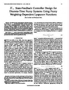
process interactions, the selection of the best pairing of controlled and manipulated variables for a multi-loop control scheme can be a difficult task [2]. In particular, for a control problem with n controlled variables and n manipulated variables, there are n possible multi-loop control configurations. Single input and single output process with multiple disturbances is shown in Fig.1.
Index Terms: Relative Gain Array, Frequency response, Robust, Energy transmission ratio, LabVIEW.
I.
INTRODUCTION
Control problems that have only one controlled variable and
Fig: 1.MIMO Process
Manuscript received October 05, 2010. This work was supported in part by the Department of Electrical & Instrumentation Engineering, Rajeev Gandhi Memorial College of Engineering & Technology, Nandyal. The paper title is “Design of Effective PI/PID Controller for Multi-Input Multi-Output Processes with Multiple Time Delays”.
There are basically two PI/PID based control schemes: multiloop control and decoupling control. In multiloop control, the MIMO processes are treated as a collection of multi-single loops, and a controller is designed and implemented on each loop by taking loop interactions into account. Due to their reasonable performances, structure simplicity and robustness, multiloop control has been well accepted by the process control industry and considerable effort has been dedicated to improve the performance of multiloop PI/PID controllers. Different control design techniques, such as detuning factor methods, sequential loop closing methods, independent design method and equivalent transfer function methods [1] etc., have been proposed over the years. When the interactions among different loops are modest a simple multiloop PI/PID controller is normally adequate, however, the decentralized controller design method may fail to give acceptable responses if there exist severe loop interactions. As a result, many industrial decentralized controllers are tuned loosely to ensure system stability, which causes inefficient operation and higher energy costs. For MIMO processes with severe loop interactions, the decoupling control schemes are often preferred. The decoupling control usually requires two steps, design of the decoupler to minimize the interactions among loops and design of the main loop controllers for overall system performance. The key advantages of the decoupling control approach are it allows
one manipulated variable are referred to as single-input singleoutput (SISO) control problems. But in many practical control problems typically a number of variables must be controlled, and a number of variables can be manipulated. These problems are referred to as multi-input multi-output (MIMO) control problems [1]. For most of important processes, at least two variables must be controlled, product quality and throughput. Due to the high product quality and energy integration requirements, most of modern industry processes, however, are multi-input multi-output (MIMO) processes.
The corresponding author, P V Gopi Krishna Rao, is Research Scholar of JNTU, Kakinada, and working as Associate professor with the Department of Electronics & Instrumentation Engineering, Rajeev Gandhi Memorial college of Engineering & Technology, Nandyal, India, 518501. (Phone: +91-9440277731,
[email protected]) Dr. M V Subramanyam, is with Department of Electronics & Communications, Santhiram Engineering College, Nandyal, India. Dr. K Satyaprasad, is with Department of Electronics & Communications, JNT University, Kakinada, India.
ISBN: 978-1-6123-3002-0
415
Proceedings of Second International Conference on Signals, Systems & Automation (ICSSA-11) 24-25 January, EC Department, G H Patel College of Engineering & Technology, Gujarat, India
the use of SISO controller design methods and in case of actuator or sensor failure, it is relatively easy to stabilize the loop manually, since only one loop is directly affected by the failure. However, such a design may result in very complicated control structures, especially, when the system dimension is high. Consequently, the research activities are primarily focused on TITO processes. For high dimensional processes, Wang et al. developed some methods for full dimensional PID or non-PID controllers with systematic design procedures and relatively simple system structures. However, due to the mathematic approximation of the decouplers for high dimensional process, the robustness of such a control system can not be guaranteed. Consequently, static decoupling approaches [3] which can significantly improve control performances with their robust stability comparable to that of multiloop control systems are adopted by the industry to deal with severe loop interactions for high dimensional MIMO processes . Although static decoupling is simple to design and implement, they may not always provide satisfactory closed loop performances if there exists large difference in dynamic characteristics among the transfer function elements. In this paper an equivalent PI controller is proposed for effective controlling of MIMO processes [4] and its effectiveness is shown with the example. The model is developed and simulated using LabVIEW. Consider an open loop stable multivariable system with n-inputs and n-outputs as shown in Fig. 1, where ri i = 1, 2, . . . , n are the reference inputs; ui, i = 1, 2, . . . , n are the manipulated variables; yi, i = 1, 2, . . . , n are the system outputs, GP(s) and Gc(s) are process transfer function matrix and full dimensional controller matrix with compatible dimensions.
II.
PAIRING OF CONTROLLED AND MANIPULATED VARIABLES
Consider the important general problem of how the controlled variables and the manipulated variables should be paired in a multi-loop control scheme. An incorrect pairing can result in poor control system performance and reduced stability margins. The relative gain array method [2] is a systematic approach for determining the best pairing of controlled and manipulated variables,. Bristol developed a systematic approach [5] for the analysis of multivariable process control problems. This approach requires only steadystate information and provides two important results 1. A measure of process interactions. 2. A recommendation concerning the most effective pairing of controlled and manipulated variables. Bristol’s approach is based on the concept of a relative gain. Consider a process with n controlled variables and n manipulated variables. The relative gain ij between a controlled variable yi and a manipulated variable u j is defined to be the dimensionless ratio of two steady-state gains:
ij =
(y i / u j ) u (y i / u j ) y
=
openloopgain closedloopgain
(3)
For I = 1, 2… n. In above equation the symbol (y i / u j ) u denotes a partial derivative that is evaluated with all of the manipulated variables with u j held constant. This term is the open loop gain (or steady-steady gain) between yi and u j , which corresponds to the gain matrix elements k ij . Similarly,
(y i / u j ) y is evaluated with all of the controlled variables with yi held constant. This situation could be achieved in practice by adjusting the other manipulated variables using controllers with integral action. (y i / u j ) y can be
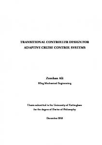
Fig .2. Closed loop multivariable control system.
interpreted as a closed loop gain which indicates the effect of u j on yi when all of the other controlled variables
The process transfer function matrix for n × n system is
G p 11 ( s ) Gp(s)= G p 21 ( s ) .... G pn1 ( s )
G p12 ( s ) G p 22 ( s ) .... G pn 2 ( s )
.... G p1n ( s ) .... G p 2 n ( s ) .... .... .... G pnn ( s )
( y i y j ) are held constant. (1)
And the controller matrix for n × n system is G c1 1 ( s )
G c12 ( s ) G c 22 ( s )
.... ....
.... G cn 1 ( s )
.... G cn 2 ( s )
.... ....
G c(s) = G c 2 1 ( s )
G c1n ( s ) G c 2 n ( s ) .... G cnn ( s )
(2)
It is convenient to arrange the relative gains in a relative gain array (RGA), denoted by
11 12 22 21 .... .... n1 n 2
.... 1n .... 2 n .... .... .... nn
(4)
respectively. ISBN: 978-1-6123-3002-0
416
Proceedings of Second International Conference on Signals, Systems & Automation (ICSSA-11) 24-25 January, EC Department, G H Patel College of Engineering & Technology, Gujarat, India
gij ( s ) as
Expressing the energy transmission ratio of c ,ij
eij kij
0
g 0ij ( j ) d
We approximate the integration of eij
Where g ij (s ) is the equivalent close loop transfer function of g ij (s) when all other loops are closed. For overall system,
(5) by a rectangle area, i.e.
the above equation can be written in a matrix form which results in the dynamic relative gain array (DRGA) 11 ( s ) 12 ( s ) ( s ) ( s ) 22 ( s) 21 .... .... ( ) s n 2 ( s) n1
eij g ij (0) c ,ij
Where
cij
, i, j = 1,2… n is the critical frequency of the transfer function
g ij (s) which can be defined in two ways. 1.
(7)
cij bij , where bij for i,j = 1, 2, . . . , n is the bandwidth of the transfer function
g
0 ij
( j )
and
determined by the frequency where the magnitude plot of frequency response reduced by 0.707 times, i.e.,
g ij ( j b ,ij ) 0.707 g ij (0) 2.
.... 1n ( s) .... 2n ( s ) .... .... .... nn ( s )
cij = uij , where uij for i, j = 1, 2,…, n is the ultimate frequency of the transfer function
g
0 ij
( j )
and determined by the frequency where the phase plot of i.e., frequency response across – ,
arg g ij ( j u ,ij )
cross over frequency information [6], i.e., ultimate frequency ( uij ) is recommended if applicable for calculation of eij , since it is closely linked to system dynamic performance and control system design. We will use uij as the basis for the following development. For the frequency response of g ij ( j ) , eij
g
0 ij
is the
( j ) |
represents the magnitude of the transfer function at various frequencies, eij is considered to be the energy transmission ratio from the manipulated variable u j to the controlled variable yi . When a MIMO control system is closed, there exists interactions among loops as a result of the existence of non-zero off-diagonal elements in the transfer function matrix. The interactions can be dynamically measured by the dynamic g ij ( s ) relative gain defined by ij ( s) g ij ( s ) (6)
ISBN: 978-1-6123-3002-0
(s)
=
For transfer function matrices with some elements without phase crossover frequencies, such as first order or second order without time delay, it is necessary to use corresponding bandwidths as critical frequencies to calculate eij . However, it is worth to point out that the phase
area covered by g ij ( j ) up to uij . Since |
Substituting Eq. (2) into (3) results in g 11 ( s )
g 12 ( s )
g 11 ( s )
g 12 ( s )
g 21 ( s )
g 22 ( s )
. .. ..
. .. ..
. .. .
. .. .
.. ..
g n1 ( s )
g n2 (s)
.. ..
g 21 ( s )
g 22 ( s )
g n1 ( s )
g 11 ( s ) g (s) 21 .... g n1 ( s ) 1 g 11 ( s ) 1 g (s) 21 .... 1 g ( s ) n1
g n2 (s)
g 1n ( s ) g 1n ( s ) g 2n (s) g 2n (s) .. .. g nn ( s ) g nn ( s )
g 12 ( s ) .... g 1n ( s ) g 22 ( s ) .... g 2 n ( s ) .... .... .... g n 2 ( s ) .... g nn ( s ) 1
g12 ( s ) 1
g 22 ( s ) .. .. 1
.. ... .. ... .. ..
g n2 (s)
.. ..
1 g 1n ( s ) 1 g 2n (s) .. .. 1 g n n ( s )
(8) is the hadamard product. Where the operator Since g ij ( s ) is controller dependant, it is impossible to compute K(s) without knowing the controller parameters. By assuming the process is under perfect control, a simple computational algorithm for K(s) can be obtained to calculate the relative gains [2] at each frequency point; ( s) G (s ) G
g 11 ( s ) g ( s) 21 .... g n1 ( s )
T
(s )
g 12 ( s ) g 22 ( s )
.... ....
.... g n2 (s)
.... ....
g 1n ( s ) g 2n ( s ) .... g nn ( s )
417
Proceedings of Second International Conference on Signals, Systems & Automation (ICSSA-11) 24-25 January, EC Department, G H Patel College of Engineering & Technology, Gujarat, India
g 11 ( s ) g (s) 21 .... g n1 ( s )
III.
g 12 ( s )
....
g 22 ( s )
....
.... g n2 (s)
.... ....
g 1n ( s ) g 2 n ( s ) .... g nn ( s )
T
(9)
For the overall system, the energy transmission ratio [1] can be expressed by effective energy transmission ratio array and given by
Where
e 12 e 22
.... ....
....
....
en2
....
e1 n e 2 n G (0 ) .... e nn
g11 (0) g12 (0) g (0) g (0) 22 G(0) 21 .... .... g n1 (0) g n 2 (0)
and
Ω
(10)
c,11(s) c,12 (s) Ω = c,21(s) c,22 (s) .... .... ( s ) c,n2 (s) c,n1
ij
ij
c,ij
(16)
between output variable yi and input variable u j when all other loops are closed. When the effective relative gains are calculated for all the input/output combinations of a multivariable process, it results in an array, ERGA, which can be calculated by
The ERGA based loop pairing rules requires that manipulated and controlled variables in the main loop be paired by those pairs whose ERGA values are positive and closest to 1.0. According to Effective relative gain array [4], Place the qualified pairs to the diagonal position and rewrite Eq. as
.... .... ....
1n 2 n .... nn
.... 1n ( s ) .... 2 n ( s ) .... .... .... nn ( s )
is the hadamard division, ij and
ij are the steady
state relative gain and relative critical frequency of loop i - j, respectively. By Using relative gain array ( ij ) and relative frequency array (
ij ), we can now determine the equivalent
transfer function g ij (s ) . Rewrite g ij ( j ) as
g ij ( s ) g ij (0)e
lij s
Where g ij (0) , l ij and (12)
....
12 22 .... n2
11 ( s ) 12 ( s ) ( s ) ( s ) 22 21 .... .... n1 ( s) n 2 ( s )
Where
ISBN: 978-1-6123-3002-0
(15)
11 21 .... n 1
Where e ij is the effective energy transmission ratio
E E T
(14)
(11)
.... 1n .... 2 n .... .... .... nn
1 n 2 n .... .... .... nn
Which can also be expressed in matrix form, i.e., relative frequency array (RFA), and calculated by
two effective energy transmission ratio
11 12 22 21 .... .... n1 n 2
.... ....
12 22 .... n 2
ij
c,ij
variable yi and input variable u j is define as the ratio of
eij
Which can be calculated
ij
We obtain
The effective relative gain [4], ij , between output
ij
g ij (0)
11 G G T (0) 21 .... n1
.... c,1n (s) .... c,2n (s) .... .... .... c,nn (s)
eij
(13)
by Eq. (9) with s = 0,
ij
.... g1n (0) .... g 2 n (0) .... .... .... g nn (0)
g ij (0) c,ij
g ij (0)
Since
EFFECTIVE REALTIVE GAIN ARRAY(ERGA)
e11 e E 21 .... e n1
g ij (0) c,ij
(17)
g ij0 ( s )
g ij0 ( s) are steady state gain,
time delay and normalized transfer function of g ij (s) excluding time delay, i.e.,
g ij0 (0) = 1, respectively. As control
loop transfer functions when other loops closed will have similar frequency properties with when other loops open if it is well paired , we can let the effective transfer functions have the same structures as the corresponding open loop transfer functions but with two different parameters, i.e.,
g ij ( s ) g ij (0)e l
ij s
g ij0 ( s )
(18)
418
Proceedings of Second International Conference on Signals, Systems & Automation (ICSSA-11) 24-25 January, EC Department, G H Patel College of Engineering & Technology, Gujarat, India
In Eq. (17), g ij (0) reflects the gain change and can be
g c , ji ( j
p , ij
) g ij ( j
g , ij
) 1
determined by Eq. while lij reflects the change in critical frequency. Although the critical frequency is generally affected by both time constant and time delay, they are exchangeable by linear approximation, it is reasonable to change only time delay to reflect the phase changes in the low frequency range which is given by
l ij
c ,ij c,ij
(19)
lij ij lij
The design of full dimensional PI/PID controller consists of two parts: 1. 2.
Off-diagonal controllers: The main task of the off diagonal controllers is to minimize the interactions among loops. Diagonal controllers: The diagonal controllers are to provide the desired performance of the closed loop control system.
The standard PID controller [8] is adopted as
g c ,ij (s) k p , ji
1
k i , ji s
k d , ji s
(20)
Rewrite Eq. (19) as
As 2 Bs c s Where A kd , ji / k ji , B k p, ji / k ji andC ki, ji / k ji
k p , ji k i , ji k d , ji
ij 2 A l g (0 ) m , ij ij ij ij
The forward transfer functions according to equations becomes
s
g ii ( s )
lij s
(21)
Denoting the gain and phase margin specifications [9] as Am ,ij and m,ij , and their crossover frequencies as g ,ij
g ( j g , ij ) g ij ( j g , ij arg c , ji
)
(23)
g ii ( 0 ) e l ii s a 2 , ii s a 1 , ii s 1 2
(24) Again, following the gain and phase margins approach, the controller parameters of main loops are given as k p ,ii k i , ii k d , ii
2 A l g (0 ) m , ii ii ii
a 2 , ii 1 a 1 ,ii
(25)
LabVIEW MODEL
1 . 26 0 .3 s 9 .5 s 1 e 4 . 28 0 . 35 s e 9 .2 s 1
The relative gain array (RGA) of the above process transfer function matrix is
1 . 5994 0 . 5994
Λ=
and p,ij , respectively, we have,
Once loop interactions are dealt with the off-diagonal decoupling controllers, the diagonal loops can be considered as n independent loops [10]. Each controller can be independently designed by single loop approaches based on the corresponding diagonal transfer functions,
2 . 16 s G(s) = 8 s 1 e 2 . 75 1 .8 s 9 .5 s 1 e
A a 2 ,ij , B a1,ij andc 1
e
a 2 , ij 1 a 1 , ij
0 . 5994 1 . 5994
For distillation column problem the effective energy transmission ratio is
3 . 564 2 . 585
E=
6 . 678 19 . 688
For distillation column problem the effective relative gain array is
Am ,ij g c , ji ( j g ,ij ) g ij ( j g ,ij ) 1 ISBN: 978-1-6123-3002-0
(22)
Consider a Luyben and vinnate (1972) distillation column model [11] is given by
By selecting
g ij (0)
Considering above Eqs the PID parameters are given by
IV.
g c ,ij ( s ) k ji
g c , ji ( s) g ij ( s) k ji
m ,ij arg g c , ji ( j p,ij ) g ij ( j p ,ij )
419
Proceedings of Second International Conference on Signals, Systems & Automation (ICSSA-11) 24-25 January, EC Department, G H Patel College of Engineering & Technology, Gujarat, India
E
E
T
1 . 325
0 . 326 1 . 325
= 0 . 326
1.2
1
For distillation column problem the Relative frequency array is
0 . 5438 0 . 8284
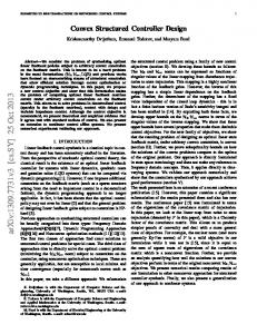
0.6 y2
= 0 . 8284 0 . 5438
0.8
0.4
For distillation column problem [11] the full dimensional controller matrix is
0.2
0
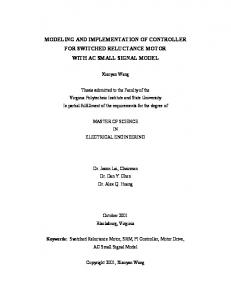
0.145 0.07125 0.676 1.1635 s s Gc (s ) 8.7028 0.916 1.9294 0.2097 s s
Diagonal controllers are main loop off-diagonal controllers are decouplers.
controllers,
-----Decoupling ___proposed
-0.2
0
10
20
30
40 Time (min)
50
60
70
80
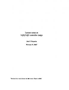
Fig.5. second output of distillation column and
The proposed method is best compared with existing methods. REFERENCES
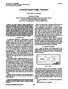
[1] [2] [3] [4] [5] Fig.3: LabVIEW Programming V.
[6]
SIMULATION RESULTS
The simulated results of above model is given below
[7]
1.4
[8]
1.2
[9]
1
0.8 y1
Q. Xiong, W.-J. Cai, M.-J. He, “A practical loop pairing criterion for multivariable Processes”, Journal of Process Control 15 (2005), pp, 741–747 Y.Y.Liu, W.D. Zhang and L.L. Ou, “Analytical decoupling PI/PID controller design for two-by-two processes with time delays”, IET Control Theory Appl., Vol. 1, No. 1, January 2007 Q. Xiong, W.-J. Cai, “Effective transfer function method for decentralized control system Design of multi-input multi-output processes”, Journal of Process Control 16 (2006) ,pp 773– 784. E.H.Bristol, “On a new measure of interactions for multivariable process control”, IEEE Transaction on Automatic control 11, pp, 133134,(1966). W.K.Ho,T.H.Lee,W.Xu,J.R.Zhou,and E.B.Tay , “The direct Nyquist array design of PID controllers” IEEE transactions on Industrial Electronics 47, pp 175-185,(2000). D. Chen, D.E. Seaborg, “Design of decentralized PI control systems based on Nyquist Stability analysis”, Journal of Process Control 13 (2003), pp, 27–39. D.chen and D.E.Seborg, “Multi-loop PI/PID controller design based on Gershgorin bands” , IEEE proceedings –Control theory and applications 149, 68-73,(2002). B. Wayne Bequette, “Process control (Modeling, Design, and Simulation)”, Eastern Economy Edition-PHI publications, 2003.
[10] nd
Donald R. Coughanowr, “Process Systems Analysis and Control”, 2 Edition, McGraw-Hill Publications, 1991.
-----Decoupling ___proposed
0.6
Qiang Xiong, Wen-jian cai, and Mao-jun He, “Equivalent transfer function method for PI/PID controller design of MIMO processes” ,Journal of process control, vol (17),pp,665-673,(2007).
[11]
Dale E. Seborg, Thomas. F. Edgar, Duncan A.Mellichamp, “Process Dynamics and Control”, 2nd edition, John Wiley & Sons (ASIA) Pvt Ltd, 2003.
0.4
0.2
0
0
10
20
30
40 Time (min)
50
60
70
80
Fig.4: First output of distillation column
ISBN: 978-1-6123-3002-0
420