International Journal of Hybrid Information Technology Vol. 9, No.6 (2016), pp. 107-116 http://dx.doi.org/10.14257/ijhit.2016.9.6.09
Design of Fuzzy Sliding Mode Controller for Suspended-floater Servo System Bo You, Yang Gao, Jiazhong Xu, Wenbo Xie and Zhi Li College of Automation, Harbin University of Science and Technology Harbin, 150080, China
[email protected] Abstract A fuzzy sliding mode control method is proposed to eliminate the interference that suspended floating objects suffered in the on-ground low-gravity simulation system. Due to the change of sling swing-angle that caused by the external interference is weak, the time integral of the sling swing-angle is taken as tracking errors. Meanwhile the values of angle and the angle differential should be converged to 0. A fuzzy sliding mode controller is designed according to the dynamic model. The traditional sliding mode control method and fuzzy control method are combined in this paper. The simulation results indicate that the servo platform is capable of tracking a floating object rapidly. And the servo platform is able to move in constant velocity synchronously with the floating object while the sling is kept upright. The feasibility of applying fuzzy sliding mode control method to the field of tracking suspension floating object is verified. Keywords: suspended-floater; servo system; fuzzy sliding mode controller; simulation
1. Introduction During recent years a series of systems to simulate low gravity on ground such as the experiment systems based on free falling objects, parabolic flight, air-bearing table, neutral buoyancy, suspension system [1-4] etc. to verify the stability and security of aerospace equipment. And among these methods the suspension method is widely used. The on-ground low-gravity simulation system uses suspension method, which managing to offset the gravity of target object by providing a compensating force which acting on the center of gravity of the target object and equaling the gravity of target object while opposite to the gravity [5]. The servo control system, which is based on adjusting the swing angle on the horizontal plane, is constructed to make the servo platform following the target object instantly by offsetting the deflection angle which is brought about by target object moving horizontally. Therefore the real-time simulation of horizontal movement of aerospace equipment is realized. The servo mode is similar to the bridge crane servo control [6-9] of the construction and transportation industries. But for onground low-gravity simulation system, we need higher control accuracy and responding speed. In the field of research on servo system of suspended floating object, the suspension method is used in simulating the low-gravity environment by Carnegie Mellon University by constructing a horizontal moving system which can track the movement of robot [10]. Japanese researchers have applied the suspension method to the microgravity experiments of space robot and studied the multi-sling suspension active control system [11]. The extravehicular free mobile robot system developed by the 502 institute of CASC is also a suspension counterweight experimental system [12]. The Institute of Intelligent Machines of Chinese Academy of Sciences also developed microgravity simulating system, and Yansheng Yao etc. proposed a method [13] which realized the movement of target object
ISSN: 1738-9968 IJHIT Copyright © 2016 SERSC
International Journal of Hybrid Information Technology Vol. 9, No.6 (2016)
using rotating arm and mobile basement aiming at solving the problems of servo control in suspension system. The method is implemented by measuring the velocity of target object and tracking the trajectory of displacement servo equipment, so as to pull target object along planning trajectory and realize following up in real time. Xumei Lin etc. [14] analyzed the deflection angle and deflection displacement after impact in polar coordinates and design a self-learning controller based on fuzzy cerebellar model. Although all the methods described above have realized the real-time servo of target object in suspension low-gravity simulating experiments, they are pre-planning methods which can only be used in certain conditions, therefore not capable of responding to external random interference and not robust. Meanwhile the driving force is often used as control term in the control algorithm of motor driving suspended-floater servo system, but the accuracy of direct controlling motor torque is poor. Hence a kind of fuzzy sliding control method [15-16], aiming at enhancing the anti-jamming capability and improving control accuracy of suspended-floater servo system, is presented in this paper. And the time integral of the sling swing-angle is taken as a tracking error while controlling angle and the angle differential to zero. The result of the control law, time interval of which can be used to control the velocity of motor directly, is used as the acceleration of the motor.
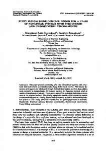
2. Control Principle of Servo System The schematic diagram of the on-ground low-gravity simulation system of suspension is shown in Figure 1. Y-rail
servo platform X-rail
sling target object
bracing truss
Figure 1. The Schematic Diagram Of The On-Ground Low-Gravity Simulation System Of Suspension The system consists of two parts, the constant tension system and the two-dimensional servo system. The function of servo control is to weaken the interference that the target object suffered in the on-ground low-gravity simulation system, which includes a vertical servo control and a horizontal servo control. The vertical control is realized by the constant tension system which can provide compensation force to the centroid of the target object. The horizontal servo control is realized by the two-dimensional servo system. When the target object is suffered interference in horizontal direction, the swing angle that is measured by auto-collimator based on PSD is used as input to the two-
108
Copyright © 2016 SERSC
International Journal of Hybrid Information Technology Vol. 9, No.6 (2016)
dimensional servo system. The X and Y direction servo motors run under the control of the servo system, then the servo platform follows the target object in horizontal plane.
Z
x
M
X
P
l F1
J mg
Figure 2. The Plane Diagram Of Suspended Servo System The plane diagram of suspended servo system is shown in Figure 2. The target object is connected with the servo platform through the sling, l is the length of sling, m is the mass of the target object. The swing angle will be generated when the target object is suffered jet thrust from horizontal direction. Because the impulse jet is only 1 N gs and the change of swing angle is small, it is difficult to control precisely by using traditional control methods. Design of fuzzy sliding mode controller for suspended-floater servo system is presented in this paper. According to the sliding mode reaching condition, the switching gain can be effectively estimated and the interference is eliminated by the switching gain. Then the jitter will be weakened. In order to simulate the dynamic effect of ideal low-gravity environment, satisfy condition: t
dt 0 t0
In order to keep the moving of servo platform and the target object synchronously after tracking process end, satisfy conditions:
(t ) 0 & (t ) 0
3. Design of Fuzzy Sliding Mode Controller 3.1. The Structure of Control System The traditional way of solving servo problem is to plan the trajectory of servo platform by measuring the displacement and velocity of target object movement, and then the servo control is achieved in horizontal direction. This method belongs to one kind of preplanning method , which not only has a complicated process, but also belongs to the open loop system. It cannot realize that the desired trajectory of target object is changed in the real-time. The thinking of this paper is that build a closed-loop control system which based on swing angle adjustment, then keep the sling vertical in real-time. The
Copyright © 2016 SERSC
109
International Journal of Hybrid Information Technology Vol. 9, No.6 (2016)
dynamic characteristics of the suspension low-gravity simulation system [17] are described as follows:
& & & & & ( M m) x Cx ml F
(1)
Cs & & & & & ml mx mg J l
(2)
C is the damping coefficient of the linear guide in the servo platform, M is the mass of the servo platform, m is the mass of the target object, g is the gravity acceleration, l &is the acceleration of swing angle, x& is the sling length, is the value of swing angle, & &is the acceleration of servo platform. is the velocity of servo platform, x& The structure of the control system is shown in Figure 3. fuzzy controller
K
G
J
r
sliding mode controller
model of the servo system
x
Figure 3. The Structure of the Control System According to the Formula(1) and the Formula(2), F and J are the two inputs of this system. But the jet thrust of the experimental object J is not controllable from the control point of view. So the system is a typical under-actuated system and only the driving force of the servo platform can be used as a control variable. But the control precision of motor torque mode which is related to the driving force control is poor. In contrast the control precision of motor speed mode which is related to the control of speed or acceleration is relatively high. For this reason the result of the control law, time interval of which can be used to control the velocity of motor directly, is used as the acceleration of the motor. The control accuracy of the servo system is improved by applying this method. 3.2. Design of Sliding Mode Controller The purpose of this paper is that control the servo platform to follow the moving target object in horizontal plane and keep the sling vertical. A fuzzy sliding mode controller is designed for this purpose. First, deform the dynamic equation. Formula(2) becomes: & & x
Cs & 1 & & ( J ml mg ) m l
(3)
Using Formula(3), Formula(1) becomes: & &
C ( M m) & M m F ( M m) Cx& J s g Ml Mml Mml 2 Ml Ml
(4)
Using Formula(1), Formula(2) becomes: & & & F Mx Cx
CS & mg J l
(5)
Using Formula(5), Formula(4) becomes: & &
110
Cs & m C ( M m) & M m 1 J ( M m) J & & x g s g l Ml 2 Ml Ml Mml Mml 2 Ml
(6)
Copyright © 2016 SERSC
International Journal of Hybrid Information Technology Vol. 9, No.6 (2016)
As the mass of the servo platform is much larger than the mass of target object, it can be regarded as
1 0 . Using this condition, the dynamic equation(6) can be simplified: M & &
Cs & 1 1 J & & x g l ml 2 l ml
(7)
According to the dynamic equation(7), the following system equation is designed: z& 1 z2 & z& 2 z3 Cs & 1 1 J & & z& u& g 3 2 l ml l ml
In the system equation, u&is the input of control, m is the mass of the target object. g is the gravity acceleration. l is the length of sling. J is the interference which the target object is suffered. Design of error equation:
e1 z1 e2 e1 z 2 e e z 1 3 3 Set sliding mode control law:
s c1e1 c2 e2 e3 c i >0 , i =1 , 2; By Formula(7) can be known, without considering the interference, the controlled object can be described as: Cs & 1 1 (8) & & & & x g l
Take s& 0 , then:
ml 2
l
& & s& c1e& 1 c2 e2 e3 C 1 1 c1 z2 c2 z3 u& s2 z2 gz3 l ml l
So the equivalent controller is designed for:
c g ueq l[c1 c2 s 2 ] l ml
(9)
Design switching controller:
usw l[ K (t )sgn(s)] , K (t ) max J (t ) , >0 . 3.3. Design of Fuzzy Rules Design sliding mode control law:
c g u ueq usw l[c1 c2 s 2 ] l[ K (t )sgn(s)] l ml 1 2 Take the Lyapunov function V s , then: 2 V ss s (c1e1 c2e2 e3 ) C 1 1 s(c1 z2 c2 z3 u s2 z2 gz3 J (t )) l ml l
(10)
(11)
Using Formula(10), Formula(11) becomes:
V s( K (t )sgn(s) J (t )) K (t ) s J (t )s s
Copyright © 2016 SERSC
111
International Journal of Hybrid Information Technology Vol. 9, No.6 (2016)
In the sliding mode control law(10), the switching gain K (t ) is the reason of producing chattering. K (t ) is used to compensate for the uncertain item J (t ) , in order to ensure that the exist condition of the sliding mode existence is satisfied. If J (t ) is changed in real-time, then in order to reduce the chattering, K (t ) should also be changed in real-time. Fuzzy rules can be used to realize the change of K (t ) according to the experience. The exist condition of sliding mode is ss