Design of High performance MIPS-32 Pipeline Processor Dr. Dilip Kumar
Kirat Pal Singh
Academic & Consultancy Services Division Centre for development of advanced computing (C-DAC), Mohali, India Email:
[email protected]
VLSI Design Department Centre for development of advanced computing (C-DAC), Mohali, India Email:
[email protected]
Abstract - The paper describes the design and synthesis of a basic 5 stage pipelined MIPS-32 processor for finding the longer path delay using different process technologies. The large propagation delay or critical path within the circuit and improving the hardware which causes delay is a standard method for increasing the performance. The organization of pipeline stages in such a way that pipeline can be clocked at a high frequency. The design has been synthesized at different process technologies targeting using Spartan3, Spartan6, Virtex4, Virtex5 and Virtex6 devices. The synthesis report indicates that critical path delay is located in execution unit. The maximum critical path delay is 41.405ns at 90nm technology and minimum critical path delay is 6.57ns at 40nm technology. The performance comparison result at different technologies shows that pipeline processor can work at 178MHz in 40nm technology i.e. 49.7% better than other technologies.
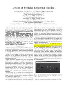
described. For describing the processor architecture, a basic model is chosen. Fig. 1.1 represents the top-level schematic of the MIPS pipelined processor. This schematic shows the principal components, or main blocks of the processor. It was a fixed-point processor and consist five stages, i.e. fetch, decode, execute, memory access, and write back. The MIPS architecture is included 47 instructions. The register file has thirty two 32-bit registers. This processor has a 32-bit address bus and a 32-bit data bus. The most important feature for evaluating a design is maximum attainable frequency. It can be found by detecting the longest delay or critical path within the different stages of the processor. In this design the critical path was located in ALU stage or execution stage.
Keywords- MIPS Processor, Datapath, ALU, register file, pipeline
I. INTRODUCTION The worldwide development of high end, sophisticated digital design system created a huge demand for high speed and low power general purpose processor. The performance of processor has increased exponentially since their launch in 1970. Today a high performance processor has a significant impact on the commercial market place. Different processor architecture have developed and optimized to achieve better performance. The MIPS is known as one of the best RISC processors ever designed, and grew out of research started at Stanford University. It came in about 1987, from the MIPS project. Along with the Berkeley RISC projects, the Stanford MIPS project was one of the first publicly known implementations of the Reduced Instruction Set Computer (RISC) architecture. Among all the current RISC architectures, MIPS remain as one of the simplest. This simplicity makes the MIPS architectures a favorite choice among universities and research labs for using as the base of their design. This simplicity also makes the MIPS architecture very attractive to the embedded microprocessor market as it enables very cost-effective implementations. A. PROCESSOR OVERVIEW A MIPS-based RISC processor was introduced in [1], is
Fig. 1.1 Top level schematic of MIPS pipelined processor
The aim of this paper is to design and synthesis a pipelined MIPS 32-bit processor at different process technology and their performance analysis. This paper is organized as follows. The related work describes as brief in Section II. The pipeline stages of MIPS are explained in Section III. Different part of pipeline stages of MIPS in detail with corresponding diagrams in various subsections. The simulation results of pipeline stages with corresponding sub-modules are shown in section IV. Verification and synthesis report are describes in section V. The conclusions of paper are described in section VI. The future scope of the paper is shown in section VII.
B. MIPS INSTRUCTION SET MIPS design was intended to simplify processor design by eliminating hardware interlocks between the pipeline stages. A MIPS processor consists of an integer processing unit and a collection of coprocessors that perform ancillary tasks or operate on other types of data [3]. Like other RISC designs, the MIPS instruction set is straightforward. MIPS are a load/store architecture, which means that only load and store instructions access memory. Other instructions can only operate on values in registers [2-5]. Generally, the MIPS instructions can be broken into three classes: the memoryreference instructions, the arithmetic- logical instructions, and the branch instructions. Also, there are three different instructions formats in MIPS architecture: R-Type instructions, I-Type instructions, and J-Type instructions as shown in Fig. 1.2. The MIPS instruction field is described in Table 1.1.
III. PIPELINE DESIGN The pipeline structure of the processor is a modified version of a popular load/store RISC [4]. The basic pipeline for a MIPS integer unit contains 5 stages: Instruction fetch (IF), Instruction decode (ID), Execution (EX), Memory access (MEM), and Write back (WB). The five stages of the pipeline can operate concurrently, using synchronization signals: Clock and Reset. MIPS instruction fetch and MIPS instruction execution is very high performance because of three types format with given length. Several simple MIPS instruction can accomplish complicated operations by compiler [8]. A. Instruction fetch unit The function of the instruction fetch unit is to obtain an instruction from the instruction memory using the current value of the PC and increment the PC value for the next instruction as shown in Fig 3.1. Since this design uses an 8-bit data width we had to implement byte addressing to access the registers and word address to access the instruction memory. The instruction fetch component contains the following logic elements that are implemented in VHDL: 8-bit program counter (PC) register, an adder to increment the PC by four, the instruction memory, a multiplexor, and an AND gate used to select the value of the next PC.
Fig. 1.2 MIPS Instruction Types Field
Description
Op[31-26]
is a 6-bit operation code
RS[25-21]
is a 5-bit source register specifier
RT[20-16] Immediate[15-0] Target[25-0] RD[15-11]
is a 5-bit target(source/destination) register or branch condition is a 16-bit immidiate, branch displacement or address displacement is a 26-bit jump target address is a 5-bit destination register specifier
Shamt[10-6]
is a 5-bit shift amount
Funct[5-0]
is a 6-bit function field
Table 1.1 MIPS Instruction Fields
II.
RELATED WORK
There has been a lot of previous research work on improving the performance of pipeline RISC based processor. XiangYunZhu et.al in this paper, MIPS instruction format, decoder module function and design theory for RISC processor is analyzed. Mamun Bin Ibne Reaz et.al this paper describes a design methodology of a single clock cycle MIPS RISC Processor using VHDL to ease the description, verification, simulation and hardware realization. Shofiqul Islam et.al this paper describes a design of High-SpeedPipelined Execution Unit of 32-bit RISC Processor using verilog HDL.
Fig. 3.1. MIPS Instruction Fetch Unit
B. Instruction Decode and Write back unit The main function of the instruction decode unit is to use the 32-bit instruction provided from the previous instruction fetch unit to index the register file and obtain the register data values as seen in Fig. 3.2.This unit also sign extends instruction bits [15 - 0] to 32-bit. However with our design of 8-bit data width, our implementation uses the instruction bits [7 – 0] bits instead of sign extending the value. The logic elements include several multiplexors and the register file. The Write Back stage is where any calculated values are written back to their proper registers.
Fig. 3.4. MIPS Data Memory Unit
IV. Fig. 3.2. MIPS Instruction Decode Unit
C. Execution unit The execution unit of the MIPS processor contains the arithmetic logic unit (ALU) which performs the operation determined by the ALUop signal. The branch address is calculated by adding the PC+4 to the sign extended immediate field shifted left 2 bits by a separate adder. The logic elements to be implemented in VHDL include a multiplexor, an adder, the ALU and the ALU control as shown in Fig 3.3.
SIMULATION RESULTS
Different capabilities and features of VHDL lead to various implementation of the design in terms of performance and speed. Xilinx 12.3 software is used as synthesis tool and Xilinx ISIM is used as simulation tool. A. . Instructions fetch stage The Instruction Fetch (IF) stage fetches the instruction according to Program Counter address. The instruction fetch entity (inst_fetch) includes the following components: PC register (PC_REG), PC selector Mux (MUX), Instruction Memory (InstMEM), and PC Adder (hybrid_adder). Fig 4.1 shows the simulation result of the IF entity. As seen in the results, after InstRead is set, instruction is fetched from the branch instruction address again and the PC counter is incremented by 4, where the instructions are fetched from instruction memory. Fig. 4.2 and Table 4.1 shows the RTL structure and signal definition used in the instruction fetch stage.
Fig. 4.1. Simulation results of instruction fetch Fig. 3.3. MIPS execution unit
D. Memory access unit The data memory unit is only accessed by the load and store instructions. The load instruction asserts the MemRead signal and uses the ALU Result value as an address to index the data memory. The read output data is then subsequently written into the register file. A store instruction asserts the MemWrite signal and writes the data value previously read from a register into the computed memory address. Fig 3.4 shows the signals used by the memory unit. Fig. 4.2. RTL view of instruction fetch stage
Signal PC_in[31-0] CLK2
Function Input of program counter Input to Instruction memory Clock signal
PC_out[31-0]
Output of program counter
Inst_in[31-0]
(32-bit) instruction
Inst_address[31-0]
Instruction address
PC_out[31-0] CLK1
Read address from PC Input to Program counter Clock signal
Fig. 4.4. Simulation result of write back stage
Signal busW[31-0] Inst_out[31-0]
Function Input write data to register file 32-bit register instruction data output signal to register file
CLK3
Input clock signal to register file
InstLoad
Enable/disable write signal
RegWr
Input Register write control signal
InstRead
Enable/disable read signal
ExtOp
Input Sign extender control signal
Inst_out[31-0]
Instruction data output
RegDst
Input Register destination control signal input
Pc_out[31-0]
Instruction address input
busA[31-0]
Read data 1 output from register file
add_next_out[31-0]
prepare PC+4 for next instruction fetch
busB[31-0]
Read data 2 output from register file
Add_brn_out[31-0]
Branch address input
ext_out[31-0]
PC_sel_br
Select branch address
RS[4-0]
First register for source operand
Mux branch selected output
RT[4-0]
Second register for source operand
busA[31-0]
Jump address input
RD[4-0]
Register for destination operand
PC_sel_jmp
Select jump address
Rd_rf [4-0]
mux_pcbr_out[31-0]
Iaddress[15-0]
Extender output
Mux RD output signal Immediate addressing signal
Table 4.1. Signal definitions of instruction fetch entity
B. Instruction decode and write back stage The Instruction Decode (ID) stage decodes the machine code bits given to it by the IF stage. The Write Back (WB) stage writes the results from load and ALU instructions back to the register file. These two stages are combined into one entity because the register file is shared between the two stages. The ID/WB entity (inst_decode) contains the following components: integer register file (REGfile), sign extended module (extender), instruction decoder module (Instructiondecoder), and mux unit (MUX_5bit). Fig 4.3 and Fig 4.4 shows the simulation results of the ID/WB stage. As the results shows, the register file is read by the falling edge of the clock signal, and written with write signal.
Table 4.2. Signal definition of instruction decode entity
Fig 4.5 and Table 4.2 show the RTL structure and signal definition are used in the instruction decode stage.
Fig. 4.5. RTL view of decode stage
C. Execution stage The Execution stage (EX), executes the given instruction according to the ALU control signal. Figure 4.6 shows the simulation result of the execution stage. The execution entity (execution _ unit) contains arithmetic logic unit (ALU), shift left 2 register (shift2) Mux (MUX and MUX_5bit), ALU control (alu_control), adder (hybrid_adder). Fig. 4.3. Simulation result of decode stage
Fig. 4.7 and Table 4.3 shows the RTL structure and signal definitions are used in the execution stage.
D. Memory access stage The Memory stage (MEM) reads and writes results to and from the data memory and Executes the branch control. Fig. 4.8 shows the simulation result of the Memory Access stage. Fig. 4.9 and Table 4.4 shows the RTL structure and signal definition are used in memory access stage.
Fig. 4.8. Simulation result of memory access stage Fig. 4.6. Simulation result of execution stage
Fig. 4.9. Entity structure of memory access stage
Signal busB[31-0] ALU_out[31-0]
Function input data to DataMEM input address to DataMEM
CLK4
Input clock signal to DataMEM
MemWr
input write signal to DataMEM
MemRead
Input read signal to DataMEM
Fig. 4.7. RTL view of execution stage Data_out[31-0] signal
Output data from DataMEM
Function
busA[31-0]
Input to ALU
Table 4.4. Signal definition of memory access unit
busB[31-0]
Input to MUX asserted when low
V.
ext_out[31-0] add_next_out[31-0] Inst_out[10-6] Alu_op[2-0] func[5-0]
Input to MUX asserted ehen high and input to shf lft2 unit Input to hybrid_adder unit Input to mux_5bit asserted when low ALU operation input to alu_control unit ALU operation function
shfCtrl
Control signal to mux_5bit
ALUSrc
Control signal to MUX
add_brn_out[31-0] ALU_out[31-0]
Output of hybrid_adder unit Output of ALU unit
jump
Output of alu_control
Equal
Output of ALU unit
Table 4.3. Signal definition of execution unit
VERIFICATION AND SYNTHESIS
The complete pipeline processor stages are modelled in VHDL. The syntax of the RTL design is checked using Xilinx tool. For functional verification of the design the MIPS processor is modelled in Hardware descriptive language. The design is verified both at a block level and top level. Test cases for the block level are generated in VHDL by both directed and random way. Table 5.1 shows the corresponding symbol and an architectural body in the RTL view. For top level verification assembly program are written and the corresponding hex code from the assembler is fed to both RTL design and model the checker module captures and compares the signal from both the model and display the message form mismatching of digital values. The complete design along with all timing constraints, area utilization and optimization options are described using synthesis report. The MIPS design is synthesized at different technology as Spartan-3, Spartan-6, Virtex-4, Virtex-5 and
Virtex-6 at 90nm, 45nm, 90nm, 65nm and 40nm.In all of these devices Virtex-6 has higher performance than others. Subunits
IF
INST_MEM, PC, Add_next, mux_pcbr,mux_pcjmp
ID
Ins_decd, mux_rw, extend, reg_file
EXE
Mux_shf, shf_lf_2,Add_brn, mux_alu, ALUnit, v0
MEM
Data_MEM
WB
Mux_busW
Area
Stage
Area utilization 35000 30000 25000 20000 15000 10000 5000 0
Table 5.1 The subunits used in the different stages of the processor
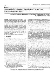
The design has been synthesized targeting 40nm triple oxide process technology using Xilinx Virtex-6 (xc6vlx240t3ff1156), 65nm triple oxide process technology using Virtex5(xc5vlx220-2ff1760), 90nm triple oxide process technology using Virtex-4(xc4vlx200-11ff1513), 45nm 9metal, dual oxide process technology using Spartan6(xc6slx150-3fgg676), 90nm dual oxide process technology using Spartan3(xc3s2005ft256) device. The Virtex family is the latest and fastest FPGA which aims to provide up to 15% lower dynamic and static power and 15% improved performance than the previous generation. It is obvious that there is a trade-off between maximum clock frequency and area utilization (number of slices LUT’s) because the basic programmable part of FPGA is the slice that contain four LUTs (look up table) and eight Flip flops. Some of the slice can use their LUT’s as distributed RAM. A. AREA UTILIZATION ANALYSIS The area utilization summary of the pipeline stage is briefly shown in Table 5.1. The area synthesis report shows that with the decrease of process technology from 90nm to 40nm the area increase. The graphical representation of the area utilization is shown in Fig. 5.1. At 40nm and 45nm technology the area is approximately twice than others technologies.
Spartan3 (90nm) Spartan6 (45nm) Virtex4 (90nm) Virtex5 (65nm) Virtex6 (40nm)
Stages
Fig. 5.1 Graphical representation shows area utilize at each pipeline stage
B. PERFORMANCE ANALYSIS In the processor, the design clock cycle was determined by calculating each element delay using the timing information summary in the Xilinx. The performance report of the pipeline stage with respect to different technology as shown in Table 5.3.the critical path delay occurs at execution stage of pipeline processor. The longest delay inside the execution stage is 19.612ns at 45nm which is reduced to 6.5ns at 40nm technology and operation frequency is 51MHz to 152MHz. Fig5.2 shows the graphical representation of Performance comparison between different stages of pipeline at different technologies. The complete pipeline stages datapth including IF, ID, EXE, MEM, WB the longest delay inside the processor is reduced from 9.102ns at 45nm to 2.102ns at 40nm process technology. This value improves operation frequency from 109.8MHz to 475.7MHz. MIPS instruction fetch (IF) and MIPS execution (EXE) shows very high performance because of three type’s instruction format with given length. Each stage of pipeline is linearly increased with the decrease of process technology. Max. attainable Frequency (MHz) Module
Area utilization
Spartan3
Spartan6
Virtex4
Virtex5
Virtex6
Technology
90nm
45nm
90nm
65nm
40nm
40nm
IF
117
237
347
377
556
19925
33067
ID
102
170
153
264
1062
298
55
55
EXE
24
51
42
91
152
421
334
461
419
MEM
471
59
1038
1024
218
13678
32885
13677
19784
32888
WB
116
159
166
255
1139
18
32
18
32
32
Module Spartan3
Spartan6
Virtex4
Virtex5
Virtex6
Technology
90nm
45nm
90nm
65nm
IF
13860
33083
13852
ID
126
55
EXE
333
MEM WB
Table 5.3 Performance analysis report Table 5.2 Area utilization summary
[4]
Frequency (MHz)
Performance Graph 1200 1000 800 600 400 200 0
Stages
Spartan3 (90nm) Spartan6 (45nm) Virtex4 (90nm) Virtex5 (65nm) Virtex6 (40nm)
[5] [6]
[7]
[8]
[9] Fig. 5.2 Graphical representation shows the performance comparison between different technology
VI. CONCLUSION MIPS processor is widely used RISC processor in industry and research area. In this paper, we have successfully designed and synthesized a basic model of pipelined MIPS processor. The design has been modeled in VHDL and functional verification policies adopted for it. Synthesis of the design is carried out Spartan3, Virtex-6, Virtex-5, Virtex-4, and Spartan6 family devices at 90nm, 40nm, 65nm, and 90nm and 45nm process technology. The simulation results show that maximum frequency in execution unit is increased from 51MHz at 45nm to 152 MHz at 40nm technology. The synthesis report indicates that each stage of pipeline in virtex6 device is clocked at higher clock frequency. So, this concludes that Virtex-6 device has high speed and high performance FPGA device than others. The complete processor design including pipeline stages is working at 178MHz frequency after synthesis at 40nm technology i.e. maximum of 49.7% better than other technologies. VII. FUTURE WORK This paper presents a comparative performance analysis and finding longer path delay at different pipeline stages using different technologies device. Our future work includes changing the processor architecture to make it capable of handling multiple threads and supporting network security application more effectively. VIII. REFERENCES [1]
[2] [3]
S.A.M Barandagh, A.Khademzadeh, “The Design of a RISC Processor Based on a Fixed-point ISA of MIPS R2000 Processor For Telecommunication Applications”, 7th WSEAS International Multiconference on Circuits, G.Kane, “MIPS RISC Architecture”, Prentice_Hall, Englewood Cliffs, N.j, 1999. D. A. Patterson and J. L. Hennessy, Computer Organization and Design, The hardware/Software Interface.Morgan Kaufmann, 2005.
[10]
Mamun Bin Ibne Reaz, Md. Shabiul Islam, Mohd. S. Sulaiman, “A Single Clock Cycle MIPS RISC Processor Design using VHDL”, IEEE International Conference on Semiconductor Electronics, pp.199-203 Dec. 2003 MIPS Technologies, MIPS32™ Architecture for Programmers Volume I: Introduction to the MIPS32™ Architecture, rev. 2.0, 2003. Diary Rawoof Sulaiman, “Using Clock gating Technique for Energy Reduction in Portable Computers” Proceedings of the International Conference on Computer and Communication Engineering pp.839 – 842, May 2008 Hema Kapadia, Luca Benini, and Giovanni De Micheli, “Reducing Switching Activity on Datapath Buses with Control-Signal Gating” IEEE Journal Of Solid-State Circuits, Vol. 34, No. 3, March 1999 Shofiqul Islam, Debanjan Chattopadhyay, Manoja Kumar Das, V Neelima, and Rahul Sarkar, “Design of High-Speed-Pipelined Execution Unit of 32-bit RISC Processor” IEEE 1-4244-0370-7 June.2006 XiangYunZhu, Ding YueHua, “Instruction Decoder Module Design of 32-bit RISC CPU Based on MIPS”Second International Conference on Genetic and Evoltionary Computing,WGEC pp.347351 Sept. 2008 Rupali S. Balpande, Rashmi S. Keote, “Design of FPGA based Instruction Fetch & Decode Module of 32-bit RISC (MIPS) Processor”, International Conference on Communication Systems and Network Technologies,2011.