be achieved using an arbitrarily small number of compactor outputs. The error-bound variable δ parametrizes the space compactor, and the synthesis approach ...
Design of Parameterizable Error-Propagating Space Compactors for Response Observation A. Morosov Department of Computer Science Potsdam University 14415 Potsdam Germany
K. Chakrabarty Department of Electrical & Computer Engineering Duke University NC 27708, USA
Abstract We present1 an efficient space compaction method which propagates all realistic errors that can appear at the outputs of a circuit under test in response to a precomputed test set. Since the proposed method does not rely on structural information of the circuit under test, it can be readily applied to intellectual property (IP) cores. Space compaction of test responses for IP cores provides parallel access to their functional outputs and reduces testing time. A δ-boundedweight error model is combined with a δ-response graph model to generate the logic specification for the compactor via graph coloring. Moreover, a carefully-chosen subset of inputs of the circuit under test allows error propagation to be achieved using an arbitrarily small number of compactor outputs. The error-bound variable δ parametrizes the space compactor, and the synthesis approach can be used to design several space compactors for the same circuit under test by simply varying δ. We illustrate the proposed method by presenting experimental results on compactor synthesis for several large ISCAS benchmark circuits.
1. Introduction Space compaction of test responses is necessary in order to reduce the volume of test data that is obtained from the observable outputs of a circuit under test. In space compaction, a k-bit-wide data stream is compressed to a q-bitwide signature stream, where q � k. The compaction process may lead to error masking, as a result of which some errors that appear at the outputs of the circuit under test are not propagated to the compactor outputs. While error masking can be made negligible for time compaction by using a linear-feedback shift register of suitable length, it remains a key problem for space compaction. A number of space compaction methods have been proposed in the literature, e. g. [2–6, 9, 13, 15, 16]. All these methods use an underlying fault model to maximize error 1 This research was supported in part by a grant from Deutsche Forschungsgemeinshaft, Germany. Prof. K. Chakrabarty was supported by the Mercator Professor Program of Deutsche Forschungsgemeinshaft, Germany. Dr. A. Morosov is now with ”Robert Bosch” GmbH.
M. G¨ossel Department of Computer Science Potsdam University 14415 Potsdam Germany
B. Bhattacharya Indian Statistical Institute Calcutta–700035 India
propagation. For example, complete error propagation for single stuck-at faults is guaranteed in [3, 5, 13]. However, these techniques are closely related to the single stuck-at fault model, therefore their effectiveness for propagating errors produced by non-modeled faults is unknown. Since a number of realistic defects cannot be modeled by classical fault models [11], it is important to consider space compactors that propagate the maximum amount of error information, irrespective of an underlying fault model. Another reason for the renewed interest in space compaction can be attributed to the emergence of system-on-achip designs using embedded cores [18]. Intellectual property (IP) cores pose a number of test challenges; for example, the system integrator is faced with the problem of propagating the test responses of an IP core to observable chip I/Os. Since the structure of an IP core is not known to the system integrator, fault simulation of the core is not possible during system integration. The core user can only use the knowledge of a precomputed test set and the set of fault-free responses. Test responses for IP cores can be observed by employing space compaction at their functional outputs. Such parallel access to a core can significantly reduces test application time. However, the space compaction methods proposed in [3–5,9,13,16] are inherently unsuitable for IP cores since they require structural knowledge about the circuit under test. An alternative approach for space compaction for IP cores was proposed recently [6]. The space compactor in [6] was designed to be independent of a test set and an underlying fault model, and it reduces 2k + 1 outputs of the core under test to k signature streams for all errors. In many situations however, a much higher amount of compaction may be desired, hence we are interested here in using the knowledge of fault-free responses for the synthesis of space compactors with an extremely small number of outputs. More recently, the concept of orthogonal transmission functions was utilized to design space compactors that propagate all errors produced by a precomputed test set T [15]. However, the need to propagate all errors (irrespective of their likelihood of occurrence) leads to an increase in the number of compactor outputs q, and requires additional testing time. In this paper, we present a general approach for designing error-propagating space compactors that relies only on
the knowledge of a precomputed compact test set T (and fault-free test responses) for the circuit under test. It can be easily used for IP cores for which the core vendor provides a precomputed test set. The proposed compactor design method makes no restrictive assumption about an underlying fault model, and no information is required about the internal structure of the core. It can therefore be directly used for compacting the test responses at the functional outputs of an IP core. Even if the structure of the core is known, e. g. for soft cores, the proposed approach alleviates the need for computationally-intensive fault simulation. The number of outputs q in an error-propagating compactor can be minimized more effectively if, instead of propagating all errors as in [6, 15], we assume a realistic error model, and in particular, if we only target error vectors of bounded weight. The weight of an error refers to the number of output bits of the circuit under test that are erroneous. We assume here that upto δ (δ � k) bits of the circuit under test may be in error, and refer to this as the δ-bounded-weight error model. Experimental results for single stuck-at faults suggest that this is indeed the case – most faults are sensitized to only a small number of primary outputs by compact test sets [4,16] and by pseudorandom inputs [10]. We expect similar results to hold for other, non-classical fault models. A similar assumption was justified in [12] for testing nonisolated legacy cores. We refer to space compactors that propagate all δ-bounded-weight errors as δ-error propagating compactors. Even though the compactor design procedure relies on δ, the overall approach is general and can be used for any value of δ. We present a new graph model, termed the δ-response graph model, for designing δ-error propagating space compactors. The proposed method also utilizes the inputs of the circuit under test for compacting the test responses. It was shown recently in [2] that given a test set T , complete error propagation can be achieved for all errors with q = 1 if all the inputs of the circuit are also fed to the compactor. This benefit however comes at the cost of increased interconnect area. In this work, we show that only a subset of the inputs of the circuit need to be fed to the compactor. In particular, we exploit the synergy between the graph model and the idea of using only a small subset of the circuit inputs to design δ-error propagating space compactors with an arbitrarily small q. If the compactor is designed using only the outputs of the circuit under test, then q is obtained from the chromatic number of the δ-response graph. On the other hand, q can be made arbitrarily small by selecting a subset of the inputs of the circuit under test for compactor synthesis. The inherent flexibility of the proposed method allows the compactor to be designed for both these cases. In fact, δ parametrizes the space compactor, and the proposed synthesis approach can be used to design several space compactors for the same circuit under test by simply varying δ and using this variation for compactor synthesis. We now list the main contributions of this paper: � We propose a new general method for the design of δ-error propagating compactors which propagate all δbounded-weight errors to their outputs. This design is based on the knowledge of the test and fault-free responses only. No structural information of the circuit under test is required, hence this method is directly ap-
� � �
�
plicable to IP cores. The compactor design procedure can be used for arbitrary values of δ. For any given δ, the number of compactor outputs can be made arbitrarily small by utilizing a subset of the inputs of the circuit under test for compactor design. We introduce the δ-response graph model as the main data structure for the synthesis of δ-error propagating space compactors. We relate space compactor design to a graph coloring problem for the δ-response graph Gδ and show that the number of outputs q equals the chromatic number of Gδ if the inputs of the circuit under test are not utilized for compactor synthesis. A coloring of Gδ also provides a logic specification for the space compactor. We show experimentally that only a small number of inputs of the circuit under test need to be fed to the compactor to ensure δ-error propagation with an arbitrarily small value of q. We also sketch an application of the space compaction approach for two different embedded cores test access architectures employed in industry.
The organization of the paper is as follows. In Section 2, we present δ-response graphs and present some data on these graphs for benchmark circuits. In Section 3, we describe how the inputs of the circuit under test can be used to design an error-propagating space compactor with a small, pre-determined value of q. Section 4 describes our space compactor design procedure. Finally, in Section 5, we present experimental results on the synthesis of space compactors for benchmark circuits.
2. δ-response graphs and error propagation In this section, we introduce the notion of δ-response graphs. These graphs form the main data structure that we use for the synthesis of δ-error propagating space compactors. Definition 1. Given a set of fault-free responses R = fR1; R2 ; : : : ; RN g for the circuit under test C with test set T = ft1 ; t2 ; : : : ; tN g, the δ-response graph Gδ (Vδ ; Eδ ) is defined as follows: (i) The set of nodes Vδ = fR1 ; R2 ; : : : ; RN ; R f g consists of N nodes corresponding to the fault-free responses of C to T , and an additional node R f representing all possible faulty responses of C which are not in R (ii) For Ri ; R j 2 R, the nodes Ri and R j are connected by an edge from Eδ if and only if d (Ri ; R j ) � δ, where d (Ri ; R j ) denotes the Hamming distance between Ri and R j (iii) For Ri 2 R, the nodes R f and Ri are always connected by an edge in Eδ . 0
The number of test patterns N 0 may be greater than the number of test responses N if C produces the same fault-free response for different test patterns. The minimum value of q for a δ-error propagating space compactor can now be determined in terms of the chromatic number of Gδ of Gδ . The chromatic number of a graph is the minimum number of colors required for its proper coloring.
Theorem 1. Let Gδ be the δ-response graph for a given test response set R for circuit C. If the chromatic number X (Gδ ) � 2q , then there exists a q-output δ-error propagating space compactor for (C; T ). Theorem 1 is easily understood as follows. If two nodes in the δ-response graph are connected by an edge, then they must be mapped to different output values (signatures) in order to detect a δ-bounded-weight error. A coloring of Gδ partitions the set of response values such that if a response Ri is changed to R j by a δ-bounded-weight error, then Ri and R j are assigned different colors. Every color corresponds to a unique signature value. In this way, δ-error propagating space compaction is easily achieved. The coloring of the δ-response graph therefore provides a logic specification for a δ-error propagating space compactor. Every color is simply mapped to a unique output value and logic synthesis is then used to design an efficient compactor. The node R f in the δ-response graph Gδ is connected to all other nodes Ri 2 R. Thus R f must be colored using an additional color which is different from the colors assigned to the nodes of R. To simplify the graph which is to be colored, we can easily delete R f and all edges that are incident on it. All remaining nodes in Gδ (corresponding to the test responses in R) which are not connected to any other node can also be deleted. These nodes can be colored with any color which is different from the color assigned to R f . These simple considerations considerably simplify the graph which is to be colored. Let the correct circuit response to test pattern ti be Ri . Due to a fault in C, Ri may be changed to another fault-free response R j 2 R Ri or into an output pattern R0i 2 f0; 1gk R. The latter case is represented by the node R f in Gδ . As discussed before, we assume that errors of at most δ bits can occur, and these errors are called δ-bounded-weight errors. A correct test response Ri can be changed by a δbounded-weight error to another output pattern R j , R j 2 R, if and only if Ri and R j are connected by an edge in the δ-response graph Gδ . We are interested here in designing δ-error propagating compactors that have only q � k outputs. All errors of upto δ bits at its inputs (i.e. on the outputs of C) are mapped to errors at its outputs. To achieve this, we assign different output values for the nodes in Gδ that are connected by an edge. In general, instead of binary values, we can use symbolic output values for more effective logic minimization. Nevertheless, for compact test sets, it is advantageous to map R f to the all-0 pattern. In general, a logic synthesis tool such as NOVA [14] can be used to determine the binary codes.
3. Resolution of color conflicts for arbitrarilychosen q As discussed in Section 2, the number of compactor outputs q can be determined from the chromatic number of Gδ , and a coloring of Gδ provides a logic specification for the compactor. This specification uses only the outputs of the
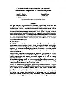
circuit under test. We next show that q can be made arbitrarily small by using a subset of the inputs of the circuit under test for compactor design. First we present an efficient heuristic procedure for coloring the nodes of a graph G using r colors, where r < X (G) [17]. An edge (u; v) in G has a color conflict if both nodes u and v are assigned the same color. The objective of the heuristic procedure that we describe below is to minimize the number of color conflicts. The first step is to color as many nodes of Gδ as possible using r < X (G) colors without conflicts. This is done using the following simple procedure. Procedure COLOR(G; r) /* Color G with r colors */ begin for i := 1 to r do 1. Select a node from G that has not been assigned a color. 2. Assign color i to v. 3. Mark all the neighbors of v. 4. Assign color i in step-by-step fashion to every unmarked node and mark its neighbors until all unmarked nodes are colored. 5. Unmark all nodes of G that have not been assigned a color. 6. Removed all nodes from G that have been assigned a color. end No color is assigned yet to some of the nodes of Gδ . We now color these nodes step-by-step in the increasing order of their degrees, and assign the color which results in a minimum number of conflicts. Consider next the design of a δ-zero aliasing compactor ? with q? outputs even though 2q < X (Gδ ). Keeping one ? color for R f 2 Vδ , we “color” the nodes of Gδ using 2q colors. Clearly, this does not yield a proper coloring, and there exists at least two nodes Ri , R j 2 Vδ R f that are adjacent to each other in Gδ but are assigned the same color. The edge (Ri ; R j ) has a color conflict, and error propagation is prevented if a fault changes the response of the circuit under test from Ri (R j ) to R j (Ri ). In order to propagate such errors through the compactor, we utilize a subset of the inputs of the circuit under test as follows. Let ti 2 T be the test pattern that produces fault-free response Ri . Similarly, let t j 2 T be the test pattern that produces fault-free response R j . Then we can distinguish between a correct output Ri in response to ti from a erroneous output Ri in response to t j by examining some of the components (bits) of the input vectors ti and t j . Let X = fx1 ; x2 ; : : : ; xn g denote the set of inputs to the circuit under test. We select a component xk of X such that xk takes different values in ti and t j . For example, let n = 4 and X = fx1 ; x2 ; x3 ; x4 g be the set of inputs to the circuit under test. Suppose ti = 1011 and t j = 1110. These two vectors differ from each other in the components x2 and x4 . Hence, we can distinguish between a correct output Ri and an erroneous output Ri in response to t j by feeding either x2 or x4 to the compactor. If we choose x2 and if β is used to symbolically denote the color assigned to Ri and R j then the compactor output is assigned a value β if (i) the output of the circuit under test is Ri and x2 = 0, and
Color 1 X = {0, 0, 0, 0}
R1
Color 1 X = {0, 0, 0, 1} R3 Rf Color 2
X = {1, 1, 0, 0} R2 Color 1
Conflict edge x1 (R1, R2) 1 (R1, R3) (R1, R4)
R4 X = {1, 0, 0, 0} Color 1
x2 1
x3 0
x4 0
0
0
0
1
1
0
0
0
Select {x1, x4}
q = 1 (two colors) X = {x1, x2, x3, x4}
x1
x4
0 1 0 1
0 0 1 0
Output
R1 R2 R3 R4 Everything else
Color Color 1 Color 1 Color 1 Color 1 Color 2
Compactor specification
Figure 1. An example illustrating the procedure for resolving color conflicts (ii) the output of the circuit under test is R j and x2 = 1. The above example illustrates the conflict resolution ? strategy for a single edge with a color conflict. If a 2 q coloring of Gδ R f results in several color conflicts, we use a greedy covering procedure to determine a near-minimal set of inputs that must be fed to the compactor. We construct a table in which the rows correspond to the edges with color conflicts and the columns correspond to the inputs of the circuit under test. An entry (i; j) in this table is 1 if the conflict on edge i can be resolved using input j. In order to resolve color conflicts efficiently, we use a heuristic covering procedure to determine a near-minimal set of columns that cover all the rows. This procedure is illustrated in Figure 1, in which one color is used to color the nodes in Gδ R f . There are three edges with color conflicts in Gδ R f and these can be resolved by selecting inputs x1 and x4 and using these for compactor synthesis. In the very rare case that different test inputs ti1 ; : : : ; tik produce the same fault free test response Ri which is equally colored as R j which is produced by the test input t j we have to determine a set of components of the inputs distinguishing between the test input t j of R j and all the inputs ti1 ; : : : ; tik of Ri . If both the equally colored test responses are generated by sets of different test inputs we have to determine a set of components of the inputs distinguishing between every test input of the first test response and every test response of the second test response. In practice such a case did never occur in our experiments.
4. Design procedure In this section, we present systematic procedures for designing δ-zero aliasing space compactors. First, we present the procedure for designing compactors that do not use the inputs of the circuit under test. Procedure COMPACTOR DESIGN 1(C; T ) /*Design a compactor for circuit under test C and test set T */
begin 1. Select a value for δ. 2. Generate the δ-response graph Gδ from the value of δ and the response of C to T . 3. Determine the chromatic number of Gδ . 4. Determine a symbolic specification of the compactor from a coloring of Gδ using X (Gδ ) colors. 5. Generate a binary specification for the compactor using tools such NOVA [14]. 6. Implement the compactor using logic synthesis tools, e.g. SIS [14]. end The above procedures can be easily automated and interfaced with SIS using Perl scripts. This requires very little manual intervention in the compactor design flow.
5. Experimental results The proposed method for designing error propagating space compactors for δ-bounded-weight errors was implemented on a Dual-CPU Pentium station with 600 MHz processors and 512 MB of memory. It was then applied to several ISCAS benchmark circuits which have relatively compact test sets. In each case, we used test sets either generated by the MINTEST program [7] or by Hansen and Hayes [8]. In the first set of experiments, we implemented the compactors without using the inputs of the CUT. For each circuit and the chosen value of δ, the minimum value of q that allowed us to achieve error propagating compaction was obtained from the chromatic number of the δ-response graph. For compactor synthesis, we used the SIS tools from Berkeley [14]. Since these tools are unable to handle very large designs, we partitioned the outputs for the larger benchmark circuits in order to ensure that the synthesis scripts ran to completion. For example, we partitioned the 320 functional outputs of s35932 into 10 partitions of 32 outputs each. In Table 1, we present the first set of experimental results for the proposed method and compare it with [15]. The value of δ chosen for these experiments was largely determined by the ease with which SIS completed the synthesis. By considering only δ-bounded-weight errors instead of all possible errors, the proposed approach provides greater compaction than [15] with comparable area overheads. In fact, in many cases, the area overhead is less than in [15]. Next, we reduced the number of outputs q for the compactors and used some of the inputs of the CUT to resolve coloring conflicts and achieve zero aliasing. This also allowed us to use higher values of δ for compactor synthesis. Table 2 shows that the area overhead increases slightly if a small number of circuit inputs are used for compactor design. However, the use of some of the circuit inputs allows higher values of δ and smaller values of q to be used effectively. Finally, we outline an application of our space compaction approach to the design of efficient test access mechanisms (TAMs) for core-based systems. A number of techniques are used in industry to access embedded cores in a system-on-a-chip [18]. For example, two TAM designs employed at Philips include the multiplexing and the distribution architectures [1]. The TAM I/Os can be dedicated
Circuit c499 c880 c3540 c6288 s9234 s35932 s38417
Test set T [8] [7] [7] [7] [7] [7] [7]
No. of patterns 52 16 84 12 105 12 68
No. of functional outputs 32 26 22 32 37 320 106
δ 32 6 4 12 4 7 4
q 2 2 2 2 7 15 8
q in [15] 2 5 7 4 — 32 28
Percentage area overhead 10.39 28.30 27.40 2.02 14.75 5.63 10.00
Percentage saving in area over [15] 0 2.14 1.07 1.37 — 0.93 0.49
Table 1. Experimental results on compactor design without using CUT inputs for resolving coloring conflicts. Circuit c6288
s35932
s38417
δ 14 15 16 17 18 19 7 8 9 10 11 4 5 6 7 8
q 2 2 2 2 2 2 20 20 20 20 20 8 8 8 8 8
No. of inputs needed 0 1 1 2 3 3 0 2 2 4 7 0 2 3 4 9
Area overhead (%) 5.06 6.25 6.70 6.68 6.89 6.93 6.38 6.44 6.52 6.65 7.08 10.00 10.65 11.24 11.82 13.63
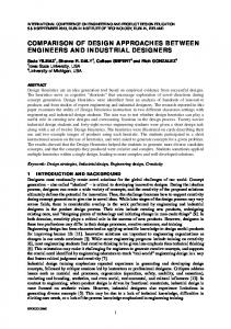
Table 2. The impact of δ and an arbitrarilychosen q on the area overhead and the number of inputs needed for zero aliasing. chip pins or they may be multiplexed with functional pins. The multiplexing architecture is sketched in Figure 2. The number of I/O pins required for the TAM can be reduced if space compaction is employed at the outputs of the embedded cores. In addition, by reducing the number the number of TAM outputs, we can use a larger number of pins as TAM inputs, thereby decreasing testing time. Similarly, space compaction can also benefit the distribution architecture as shown in Figure 3.
6. Conclusions We have described an efficient space compaction approach that offers a number of key advantages. The use of the δ-bounded-weight error model ensures that the compactor propagates all realistic errors that can appear at the outputs of a circuit under test in response to a precomputed test set. Since the proposed method does not rely on structural information of the circuit under test, it can be used to observe test responses at the functional outputs of intellectual property (IP) cores. Space compaction of test responses for IP cores provides parallel access to their functional outputs and reduces testing time. The δ-bounded-weight error model is combined with a δ-response graph model to generate the logic specification for the compactor via graph coloring. The number of compactor outputs can be made
arbitrarily small by (improperly) coloring of the δ-response graph with a predetermined number of colors and then using a carefully-chosen set of inputs of the circuit under test for resolving color conflicts. We have shown that the variable δ parametrizes the space compactor, and the synthesis approach can be used to design several space compactors for the same circuit under test by simply varying δ. We have presented experimental results on compactor synthesis for several large ISCAS benchmark circuits.
7. Acknowledgments The authors thank Erik Jan Marinissen of Philips Research Laboratories, Eindhoven, The Netherlands, for suggesting potential applications of space compaction in designing efficient test access architectures.
References [1] J. Aerts and E. J. Marinissen. Scan Chain Design for Test Time Reduction in Core-Based ICs. In International Test Conference, pages 448–457, 1998. [2] B. Bhattacharya, A. Dmitriev, and M. G¨ossel. Zero-Aliasing Space Compaction Using a Single Periodic Output and its Application to Testing of Embedded Cores. In IEEE International Conference on VLSI Design, pages 382–387, 2000. [3] K. Chakrabarty. Zero-Aliasing Space Compaction Using Linear Compactors With Bounded Overhead. IEEE Transactions on Computer-Aided Design, 17:452–457, May 1998. [4] K. Chakrabarty and J. P. Hayes. Test Response Compaction Using Multiplexed Parity Trees. IEEE Transactions on Computer-Aided Design, 15:1399–1408, November 1996. [5] K. Chakrabarty, B. T. Murray, and J. P. Hayes. Optimal ZeroAliasing Space Compaction of Test Responses. IEEE Transactions on Computers, 17:1171–1187, November 1998. [6] M. G¨ossel, E. S. Sogomonyan, and A. Morosov. A New Totally Error Propagating Compactor for Arbitrary Cores with Digital Interfaces. In VLSI Test Symposium, pages 49–56, 1999. [7] I. Hamzaoglu and J. H. Patel. Test Set Compaction Algorithms for Combinational Circuits. In International Conference on Computer-Aided Design, pages 283–289, 1998. [8] M. C. Hansen and J. P. Hayes. High-Level Test Generation Using Physically-Induced Faults. In VLSI Test Symposium, pages 20–28, 1995. [9] A. Ivanov, B. Tsuji, and Y. Zorian. Programmable BIST Space Compactors. IEEE Transactions on Computers, 45:1393–1404, December 1996. [10] V. Moshanin, V. Otschertnij, and A. Dmitriev. The Impact of Logic Optimization on Concurrent Error Detection. In 4th On-Line Testing Workshop, pages 81–84, 1998.
N
N
TAM in
Core 1
N
Core 1
Core 2
N
Core 2
N
Multiplexer
N
N
N
N
Core 2
TAM in
N
Space w compactor
N
Space w compactor
N
Space w compactor
TAM out N
N
N
Core 2
Multiplexer
System-on-a-chip
System-on-a-chip
w
TAM out
w