The approach proposed targets single chip system implementation ... efficient
solution for rapid prototyping and low cost small series production of low to
medium ... Most digital systems consist of hardware components and/or software
programs that ..... [13] “MICROCHIP DATA BOOK”, Microchip Technology Inc.,
1993.
A Parameterizable Processor Core for Fast Turnaround Co-Synthesis of Embedded Systems João M P Cardoso INESC / Univ. Algarve
[email protected]
Horácio C Neto INESC / IST
[email protected]
INESC, Rua Alves Redol 9, 1000 Lisboa, Portugal
Abstract This paper describes a parameterizable RISC processor core developed in the scope of a co-synthesis environment for embedding mixed hardware/software systems in sea-of-gates integrated circuits. The core is fully configurable so that the program and data memory sizes, the number and size of the I/O ports, the stack size and the number and type of its peripheral blocks can be automatically adjusted to the system requirements. A variable number of additional application specific hardware units are automatically synthesized and integrated in the same chip, if necessary to achieve the required performance. The approach proposed targets single chip system implementation on a quick turnaround sea-of-gates technology, therefore providing a suitable environment and an efficient solution for rapid prototyping and low cost small series production of low to medium complexity embedded digital systems.
1. Introduction Most digital systems consist of hardware components and/or software programs that execute the application specific digital function as a program running on a dedicated processor. While dedicated hardware solutions, on one side, typically guarantee the best performance at the expense of higher design time and cost, software based solutions, on the other side, allow for a faster design cycle and higher flexibility at a lower cost but often fail to meet the system timing, area and/or power consumption constraints. A better tradeoff between performance and cost can be achieved if the hardware and software components are tuned to each other. Hardware/software co-synthesis techniques that enable increased automation of the co-design process are currently an hot topic of research [1][2][3][4][5][6][7][8]. Most target architectures consist of generic processors, memory and application-specific hardware circuits. The implementation of the system components depends on the chosen technology. The different units may consist of individual ICs on a board or on a multi-chip module, or they can be integrated in the same integrated circuit. Standard cell products are already available which make the complete integration of complex megacells, such as, memory, MPU, MCU, multipliers and other advanced functions, on one chip a reality. However, with NRE costs starting at around 150KUSD, these complex IC products are still well beyond the reach of the average customer. Therefore, and for small and medium-sized enterprises in particular, it is essential to reduce all the up-front cost elements and to minimize all development risks while maintaining compatibility with well understood development environments. Recent developments on directwrite laser based lithography have enabled low cost fast prototyping and low volume
In Proceedings of the XI SBMicro Conference, Águas de Lindóia - SP - Brazil , July 29 - August 2, 1996, pp. 16 -21.
production of sea-o f-gates ICs [9][10] with the capability for one-chip integration of medium
complexity mixed hardware/software systems. In the following sections we describe the implementation of a parameterizable processor core and its associated co-synthesis environment which take advantage of the fast turnaround CMOS sea-ofgates technology [11] to provide an efficient solution to low cost one-chip system implementations.
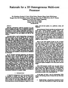
2. Processor Architecture The basic processor core, as shown in Figure 1, is based on a RISC (Reduced Instruction Set Computer) architecture and includes some common microcontroller peripherals. It has been chosen to be instruction set compatible with a commercial microcontroller, therefore taking advantage of the existence of standard development tools (simulators, cross-assemblers and emulators) and of a large number of applications [12]. This core was designated PISCPMS (P arameterized & Instruction Set Compatible PIC Microcontroller for S ea-of-Gates). Program Counter (F2) Program Memory up to 512 x 12 bits
8 bits Register File (up to 80x8 bits registers)
9-bits Stack 12 bits Instruction Register 8 bits
5 bits
MUX 5 bits FSR (F4)
RTCC (F1) Status (F3) Port B (F6) MUX Instruction decoder and Control MCLR
Port A (F5)
ALU Synchronizeer
RTCC/WDTCLK
WatchDog Timer
W
VDD, VSS Timer
TRISA OPTION
OSC1 OSC2/CLKOUT
8 bits
Clock generation
TRISB
8 bits
Figure 1. Block diagram of the basic processor core architecture.
This architecture provides a good solution for small to medium complexity embedded system applications due to its good performance, small core dimension (8-bit wide datapath), simple control units and good code compactation. It has a reduced orthogonal instruction set with 33 instructions 12 bit wide. One instruction cycle (CLKOUT) is equivalent to 3 clock cycles (OSC1). Conditional branches and instructions that write to the program counter take two instruction cycles to execute. All other instructions, including CALL and GOTO take a single cycle to execute. The Harvard type architecture uses one level of instruction pipelining (fetch of the following instruction in parallel with the execution of the actual instruction). The generic instruction execution timing diagram can be seen in Figure 2, where the following instruction steps are shown: IF
In Proceedings of the XI SBMicro Conference, Águas de Lindóia - SP - Brazil , July 29 - August 2, 1996, pp. 16 -21.
Title: Creator: CreationDate: Figure 2. Instruction execution timing diagram.
(instruction fetch), ID (instruction decoding), RO (read operand), EX (instruction execution), WO (write operand), and WS (write status register). There are three main working states: the RESET_STATE (power up), the SLEEP_STATE (a power down mode where the internal clock is deactivated by a sleep instruction for reduced power consumption) and the ACTIVE_STATE (for normal program execution). The control unit is only active in the ACTIVE_STATE. It consists of 3 concurrent finite state machines: one is synchronized in the negative clock edge and the other two in the positive edge. The use of control pipelining (insertion of registers between the control unit and the datapath) eliminates any undesired state transitions (like hazards) in the output control signals. The datapath consists of the ALU, the instruction transparent registers, the W (accumulator) register and the register file. The register file contains by default 7 registers (F0, RTCC, PC, SR, F4, PORTA and PORTB) and can be extended to a (current) maximum of 80x8 bit registers. When using more than 32 registers, a memory mapping scheme as described in [13] is used. All the input/output ports are also reconfigurable. A maximum of 8x8 bit I/O ports is currently supported, but any register can be specified as an output only port. The architecture supports the inclusion of an internal Timer and WatchDog Timer (WDT), which have been implemented to be compatible with the functionality described in [13]. The system has been specified using a VHDL subset suitable for synthesis [14]. The complete description of the PISCPMS has about 3000 lines of VHDL code. The core is available as a parameterized megacell to be instantiated by the co-synthesis environment and mapped to the seaof-gates integrated circuits [11], as described in the following sections.
3. Co-Synthesis Environment The PISCPMS core has parameterized capabilities like program memory, data memory, number of I/O ports, and number of output ports. The parameters are generated automatically from the software specification [15], so that the processor implementation can be tailored to the specific requirements of the target application. This solution doesn’t waste any memory, power consumption or data area unnecessarily. The co-synthesis environment is sketched in Figure 3. The system is specified using a software based approach directly compatible with the assembler code for the processor core. This solution permits a fine-granularity adequate for the targeted low/medium complexity embedded systems and allows direct compatibility with existent standard development systems and microcontroller applications. The information for the configurable blocks (program size, number of registers, I/O port configuration, etc.) is extracted from the compiled code and is used to guide the block generators (ROM, register file, I/O ports, ...). These blocks are specified using parameterized VHDL descriptions which provide an efficient way for automatic block generation.
In Proceedings of the XI SBMicro Conference, Águas de Lindóia - SP - Brazil , July 29 - August 2, 1996, pp. 16 -21.
MPALC (assembler)
Assembler program
MPSIM (simulator)
Code segments Analysis of execution time
with constraints extraction
assembler
VHDL sinthesizable
Number of registers
ASM -> ROM
necessary
Converter
Library Functions
SYNTHESIS
SYNTHESIS
SYNTHESIS
Program Memory
Data Memory
Interface FUs
PISCPMS CORE
Gate Array
Figure 3. Co-Synthesis environment.
The designer uses directives [15], encapsulated with the assembler, to guide the hardware/software partitioning. These directives impose timing constraints on code blocks and/or impose parallel execution of different code segments. In the case of time constraints violation and/or concurrent code segments the software component is migrated to hardware. The analysis of the hardware functional units area and timing performance is done using metrics feedbacked from the synthesis tools. The integration of each functional unit with the core is done as shown in Figure 4. The interface between the units is done through a memory mapping scheme, that does not require ...
ld_B B
B0
ALU
B1
...
B6
...
W6
FUNCTIONAL UNITS
ld_W W
W0
W1
...
enable_W
Figure 4. Interface of the hardware units with the core processor.
In Proceedings of the XI SBMicro Conference, Águas de Lindóia - SP - Brazil , July 29 - August 2, 1996, pp. 16 -21.
any modification of the core architecture (the register selection depends on the value of the 3 most significant bits of the status register).
4. Results The processor core has been implemented in a sea-of-gates integrated circuit. Logic simulations illustrated a maximum clock frequency near 35MHz. The critical path of the processor core has been identified, which consists of the increment of the program counter, followed by addressing program memory. A re-scheduling of these is under development in order to increase the maximum allowable clock frequency. The core occupies 3500 equivalent gates, the program memory occupies about 3 gates per instruction and the register file occupies about 55 gates per 8-bit register. A test application using a 135 instructions program and 13 registers, which occupies 4030 gates has been recently fabricated. This circuit includes the partial assembler code shown in Example 1, where a time constraint is specified for the multiplication routine. The execution time, in software, with the specified clock frequency of 30MHz takes 6.4µs. ;CLOCK CYCLE = 33 ns ;**************************** ;CONSTRAINT MAXTIME: mult TO end_mult = 2 us ; Main Program (...) ;**************************** ; Multiplier Routine ; mult clrf High_byte (...) clrf Low_byte movf portA,w movlw 8 movwf mulplr movwf count movf portB,w movf mulcnd,w movwf mulcnd bcf STATUS,CARRY ; loop rrf mulplr call mult btfsc STATUS,CARRY (...) addwf High_byte rrf High_byte rrf Low_byte decfsz count goto loop end_mult retlw 0 Example 1. A code segment with timing constraints.
These results violate the constraint directive and therefore the co-synthesis system migrates the routine between labels to hardware. The assembler is directly translated to a VHDL specification of the hardware unit. The synthesized unit occupies 470 equivalent gates and has a maximum execution time of 74ns. When integrated with the processor core, the task between labels takes 1.1µs of execution time, with 11 instructions for communication between the functional unit and the PISCPMS core.
5. Conclusions and Future Work An efficient approach for rapid prototyping of embedded digital systems has been achieved by combining, in a one-chip solution, a generic microcontroller core with application specific hardware units. The software/hardware co-synthesis environment proposed targets low to medium complexity applications were timing and area constraints are important, and fast turnaround and low volume system production are fundamental.
In Proceedings of the XI SBMicro Conference, Águas de Lindóia - SP - Brazil , July 29 - August 2, 1996, pp. 16 -21.
Current work emphasizes the full automation of the design environment, including the completion of the assembler to VHDL converter, and the development of a dynamic simulator to provide more accurate estimates of the software execution time. Although the communication is not critical for the final performance, we are investigating alternative interface schemes. Non deterministic code segments are currently not allowed to be migrated into hardware. The use of high level hardware synthesis algorithms able to extract these segments is envisaged. Future plans include the extension of the design system to allow the specification of the software components in C, such that the C compiler exports the constraints directives to the flow graph assembler level where the hardware/software partition is currently performed.
6. References [1]
R. K. Gupta, “Cosynthesis of Hardware and Software for Digital Embedded Systems”, PhD Thesis, Stanford University, Palo Alto, Calif., 1993
[2]
Rolf Ernst, J. Henkel, e T. Benner, “Hardware-Software Cosynthesis for Microcontrollers”, IEEE Design & Test of Computers, Vol. 10, No. 4, December 1993
[3]
Giovanni De Micheli, “Computer-Aided Hardware-Software Codesign”, IEEE Micro, August 1994
[4]
Giovanni De Micheli, “Hardware-Software Co-Design: Application Domains and Design Technologies”, in “Hardware-Software Co-Design”, Kluwer Academic Publishers, January 1996
[5]
Harry Hsieh, Luciano Lavagno, and Alberto Sangiovanni-Vincentelli, “Embedded System Codesign: Synthesis and Verification”, in “Hardware-Software Co-Design”, Kluwer Academic Publishers, January 1996
[6]
Asawaree Prabhakar Kalavade, “System-Level Codesign of Mixed Hardware-Software Systems”, PhD Thesis, EECS Dept., Univ. of California, Berkeley, 1995
[7]
Alberto Sangiovanni Vincentelli et al, “Hardware-Software Codesign of Embedded Systems”, IEEE Micro, August 1994
[8]
Daniel D. Gajski et al., “Specification And Design Of Embedded Systems”, Prentice-Hall Englewood Cliffs, 1994
[9]
Horácio C. Neto, “Fast Prototyping of Microelectronic Systems”, IV EBMicro, Escola Brasileira de Microelectrónica, Advanced Research Tutorials, Recife, January 1995
[10] QuickChips Partners, “QuickChips, A System Supporting ASIC Design and Providing Rapid Turnaround Prototyping”, Esprit Project 6043, Technical Appendix VI, September 1995
[11] “Fast ASIC Prototyping at INESC”, http://asic.inesc.pt [12] “EMBEDDED CONTROL HANDBOOK”, Microchip Technology Inc., 1993 [13] “MICROCHIP DATA BOOK”, Microchip Technology Inc., 1993 [14] Paulo Flores, “Especificação Funcional de Sistemas Electrónicos Digitais em Ambiente de Síntese”, Master Thesis (in Portuguese), IST, 1993
In Proceedings of the XI SBMicro Conference, Águas de Lindóia - SP - Brazil , July 29 - August 2, 1996, pp. 16 -21.
[15] João M. P. Cardoso, “Co-Síntese de Sistemas Embebidos em Agregados de Células Lógicas”, Master Thesis (in Portuguese), IST, 1996