Journal of Microwaves and Optoelectronics, Vol. 2, N.o 4, December 2001.
76
DESIGN OF PASSIVE RETRANSMITTING SYSTEM FOR CELLULAR COMMUNICATION Juliane Iten Chaves, Anton Gora Junior, and José Ricardo Descardeci Department of Electrical Engineering, Federal University of Parana-UFPR Curitiba, PR, C.P. 19011 CEP 81531-990, Brazil. E-mail:
[email protected]
Abstract This paper presents an analysis of a passive repeater for mobile communication consisting of an arrangement of two back-to-back Yagi-Uda antennas and reflectors appropriately designed to enhance the relay efficiency in cellular communication. The analysis will consider the redirection of the signal in azimuth and elevation, from 0 to -30°.
I - INTRODUCTION In a diffusion system for cellular communication, problems of weakness of the electromagnetic signal communication exist due to the scattering during propagation. The main reason for this problem is the geography of the land to be covered. It is necessary to redirect the electromagnetic signal to shadow zones where communication fails. This problem is even worse when the amplification of the signal is not possible for there is no source supply available, or the operation cost is critical. This paper comprises a study of a passive repeater for cellular communication. Passive repeaters are diffractive structures that can be appropriately used to shape the electromagnetic radiated fields. As far as the author’s knowledge is concerned, there is no similar result reported in the literature. The investigation is performed considering two back-to-back Yagi-Uda antennas, projected for optimum gain in both directions. Since the antennas are identical there will be no mismatch between them, the only mismatch is due to the connections with the cable linking them together. It will be considered a corner reflector in the Yagi-Uda antenna project in order to improve directivity. The Yagi-Uda antenna was invented in 1926 by Yagi and his supervisor Uda [1], and is particularly convenient in the VHF and UHF band [2], [3]. This antenna is suitable for cellular band operation and can achieve a relatively high gain [3]. In addition, it has low cost, low weight and its wire structure imposes low wind resistance. It is known that since the invention of the Yagi-Uda antenna a big effort was devoted to improve its project. One example was the work of David K. Cheng and C. A. Chen where they studied the optimum element spacing and lengths for Yagi-Uda Arrays [4], [5]. Ehrenspeck and Poehler have also published an interesting experimental paper in which they describe a method for obtaining maximum gain from Yagi-Uda arrays [2]. Another work by Mailloux describes a method for approximately analyzing the Copyright SBMO
ISSN 1516-7399
Journal of Microwaves and Optoelectronics, Vol. 2, N.o 4, December 2001.
77
behavior of finite Yagi arrays [6]. Finally, P. P. Viezbicke [7] from U.S. Government Standards Office- Washington, presented experimental investigations producing very good information for the Yagi-Uda antenna projects. In this study, one of the two back-to-back antennas is used as a receiver. The signal detected by the receive antenna is linked to the second antenna by a physical connection. The second antenna is the transmission antenna and will retransmit the signal in the desired direction. In order to reduce the back scattering and improve the directivity of the Yagi-Uda antenna a corner reflector were considered substituting the reflector element of the array. Krauss first presented a system composed by a half wavelength dipole and a corner reflector in 1938 [8], [9]. The performance of Yagi-Uda antennas with corner reflectors was studied afterwards and presented high directivity and good impedance behavior [10]. The radiated fields and impedance characteristics of the passive system are simulated by using the Method of Moments (MOM). This method describes the complex distribution of the currents on the system and can take into account the metallic supporting structure [11]. The MOM is well described in the literature [8], [12], [13]. Simulations will consider variations in the retransmission direction of 0° to -30° in azimuth and elevation.
II - DESIGN PASSIVE SYSTEM The system was designed to operate in the central frequency of fo = 840MHz. The frequency band is 10MHz [14]. The project was based on [7] and [10], and was optimized using the techniques described in [2], [4]-[7], [13] and [14].
d
S
d
d
2r
2r
X
~ Corner Refletor
0 Driven element
Ln
1
2
3
13
Directors
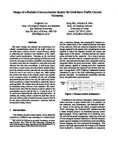
Fig 1. Passive retransmitting system consisting of two Yagi-Uda arrangements with corner reflectors located back-to-back. The right arrangement is variable in the azimuth (φ) and elevation (θ) planes.
The retransmitting system consists of two back-to-back antenna systems. Each antenna system is composed by an Yagi-Uda antenna and a corner reflector as displayed in Fig. 2 and Fig. 3. It was considered a tower mast of 10m lengths and 0.30m of diameter. The antenna systems Copyright SBMO
ISSN 1516-7399
Journal of Microwaves and Optoelectronics, Vol. 2, N.o 4, December 2001.
78
were positioned 0.60m apart each other, in order to provide mechanical support to the mast, as described in Fig. 1. The metallic parts of the retransmitting system were considered as perfect conductors.
Fig. 2. Yagi-Uda antenna configuration.
L
2c
x H
G
G
Fig. 3. 90° Corner reflector configuration.
III - RESULTS The retransmitting system was designed to operate at a central frequency of f0 = 840MHz. Table 1 lists the obtained specifications from the Yagi-Uda antenna and the Corner reflector. The YagiUda antenna system achieved 16.29dB of absolute gain. Copyright SBMO
ISSN 1516-7399
Journal of Microwaves and Optoelectronics, Vol. 2, N.o 4, December 2001.
79
The MOM was applied in order to obtain the radiation pattern of the system and take into account the mast and wire diameters. In this simulation, one Yagi-Uda antenna system were fixed and the other were varied in the azimuth (φ) and elevation (θ) planes from 00 to -300 (Fig. 1). Fig. 4 and Fig. 5 show the radiation patterns for the case where there is no redirection of the system (θ=00, φ=00), Fig. 6 the case with redirection of -300 in azimuth plane (θ=00, φ=-300) and Fig. 7 the case with redirection of -300 in elevation plane (θ=-300, φ=00). Fig. 8 show the absolute gain of Yagi-Uda antenna system assembled back-to-back to form the retransmitting system, as a function of the redirection angle. One antenna system is kept fixed while the other varies in azimuth (φ) and elevation (θ). Note that the values of the absolute gain are approximately 3dB down the value of the antenna system. This is because the power is splitted between the two antenna system. We can also note in Fig. 8 that there appears an asymmetry in the absolute gain of the antenna system, mainly in absolute angles greater than 150. This can be justified by the asymmetry in the diffraction system caused by the displacement of the transmitting antenna system (Fig. 1).
TABLE I Design of the Yagi-Uda and the Corner Reflector. f0 = 840MHz Yagi-Uda Diameter from Yagi-Uda wires 2r – 0.024λ Wire L0 L1 L2 L3 L4 L5 Length(λ) 0.455 0.401 0.401 0.397 0.384 0.380
L6 0.375
L7 0.371
Space between wires d = 0.308λ L8 L9 L10 L11 L12 0.367 0.367 0.367 0.367 0.367
L13 0.367
Corner Reflector 2c 0.056λ
S 0.35λ
L=2S 0.70λ
G 0.1λ
H 0.6λ
Fig. 4. Radiation pattern of passive retransmitting system. Gain in azimuth plane with φ=0o and θ=0o. Copyright SBMO
ISSN 1516-7399
Journal of Microwaves and Optoelectronics, Vol. 2, N.o 4, December 2001.
80
Fig. 5. Radiation pattern of passive retransmitting system. Gain in elevation plane with φ=0o and θ=0o.
Fig. 6. Radiation pattern of passive retransmitting system. Gain in azimuth plane with φ=-30o and θ=0o.
Copyright SBMO
ISSN 1516-7399
Journal of Microwaves and Optoelectronics, Vol. 2, N.o 4, December 2001.
81
Fig. 7. Radiation pattern of passive retransmitting system. Gain in elevation plane with φ=0o and θ=-30o.
13.8 13.6 13.4 13.2 13.0 12.8 12.6 12.4 12.2 12.0 0°
-5°
-10°
-15°
-20°
-25°
-30°
Az-Gain
Az-Gain-Fix
Elev-Gain
Elev-Gain-Fix
Fig. 8. Gain (dBi) in the azimuth plane from the varied Yagi-Uda system (Az-Gain) and from the fixed Yagi-Uda system (Az-Gain-Fix); and gain (dBi) in the elevation plane from the varied Yagi-Uda system (Elev-Gain) and from the fixed Yagi-Uda system (Elev-Gain-Fix).
Copyright SBMO
ISSN 1516-7399
Journal of Microwaves and Optoelectronics, Vol. 2, N.o 4, December 2001.
82
IV - CONCLUSION This paper described a passive retransmitting system for cellular communication. The retransmitter consists of two back-to-back Yagi-Uda antenna systems, supported by a tower mast. It is proposed the use of a corner reflector with the Yagi-Uda antenna, in order to enhance the directivity of the antenna systems. The use of a corner reflector will also reduce interaction between the antenna systems. This is because of the reduction in their back lobe levels. Simulations of the radiation behavior were conducted by using the moment method (MOM). In the retransmitting system one antenna system remains fixed for reception of the signal. The signal detected by the receiving antenna is linked to the second antenna system by a physical connection. The second antenna system is the transmitting antenna and will retransmit the signal in the desired direction. Simulations were performed considering aligning the transmitting antenna system in azimuth (from 0 to -300) and elevation (from 0 to -300). Simulations showed that the retransmitting system can properly redirect the signal, as we can see in Fig. 4, 5, 6 and 7. Results in Fig. 8 show that the retransmitting system gain was practically constant even for large redirection angles. It is also observed in Fig. 8 that for absolute angles θ and φ bigger than 15° there appears a small discrepancy in absolute gain of fix and variable antenna systems. This discrepancy was about 0.8dB, and is justified by physical asymmetry in the retransmitting structure. The presence of the tower mast to support the antenna system was considered in the MOM simulation. Inclusion of the input impedance to connect the two antenna systems is being carried out.
ACKNOWLEDGEMENT The authors would like to thank CNPq and CAPES, for the financial support.
REFERENCES [1] H. Yagi, “Beam transmission of ultra short wave,” Proc. IRE, 16, pp. 715-741, June 1928. [2] H. W. Ehrenspeck and H. Poehler, “A New Method for Obtaining Maximum Gain from Yagi Antennas,” IRE Trans. Antennas and Propagation, vol. AP-7, pp. 379-386, October 1959. [3] H. Schrank, “Antenna Designer´s Notebook,” Trans. Antennas and Propagation Society Newsletter, June 1985. [4] David K. Cheng and C. A. Chen, “Optimum Element Spacings for Yagi-Uda Arrays,” Trans. Antennas and Propagation, vol. AP-21, No. 5, September 1973. [5] C. A. Chen and David K. Cheng, “Optimum Element Lengths for Yagi-Uda Arrays,” Trans. Antennas and Propagation, vol. AP-23, No. 1, January 1975. [6] R. J. Mailloux, “The Long Yagi-Uda Array,” Trans. Antennas and Propagation, vol. AP-14, pp.128-137, March 1966. [7] P. Viezbicke, Yagi Antenna Design, NBS Technical Note 688, U.S. Government Printing Office, Washington, DC, Dec. 1976. Copyright SBMO
ISSN 1516-7399
Journal of Microwaves and Optoelectronics, Vol. 2, N.o 4, December 2001.
83
[8] Warren L. Stutzman and Gary A. Thiele, Antenna Theory and Design, United States of America: John Wiley & Sons, 2nd edition, 1998. [9] John Daniel Kraus, Antenna, Boston: McGraw-Hill, 1988. [10] Luís Claudio Esteves, Antenas-Teoria Básica e Aplicações, São Paulo: McGraw-Hill from Brazil, 1980. [11] Gary A. Thiele, “Analysis of Yagi-Uda-Type Antennas,” Trans. Antennas and Propagation, vol. AP-17, No. 1, January 1969. [12] Roger F. Harrington, Field Computation by Moment Methods, New York: IEEE Press, 1993. [13] Constantine A. Balanis, Antenna Theory: Analysis and Design, New York: John Wiley & Sons, 2nd edition, 1997. [14] Tech. Report: Ministério dos Transportes e das Comunicações, Portaria No 246 de 28 de julho de1992.
Copyright SBMO
ISSN 1516-7399